US1851434A - Method of heating by steam - Google Patents
Method of heating by steam Download PDFInfo
- Publication number
- US1851434A US1851434A US481825A US48182530A US1851434A US 1851434 A US1851434 A US 1851434A US 481825 A US481825 A US 481825A US 48182530 A US48182530 A US 48182530A US 1851434 A US1851434 A US 1851434A
- Authority
- US
- United States
- Prior art keywords
- steam
- vacuum
- pressure
- differential
- heating
- Prior art date
- Legal status (The legal status is an assumption and is not a legal conclusion. Google has not performed a legal analysis and makes no representation as to the accuracy of the status listed.)
- Expired - Lifetime
Links
- 238000010438 heat treatment Methods 0.000 title description 13
- 238000000034 method Methods 0.000 title description 12
- 230000007423 decrease Effects 0.000 description 11
- 230000003247 decreasing effect Effects 0.000 description 11
- 238000010586 diagram Methods 0.000 description 3
- 238000005086 pumping Methods 0.000 description 2
- 238000004326 stimulated echo acquisition mode for imaging Methods 0.000 description 2
- 101001138030 Homo sapiens Protein Largen Proteins 0.000 description 1
- 102100020860 Protein Largen Human genes 0.000 description 1
- 238000010276 construction Methods 0.000 description 1
- 238000009434 installation Methods 0.000 description 1
- KJLLKLRVCJAFRY-UHFFFAOYSA-N mebutizide Chemical compound ClC1=C(S(N)(=O)=O)C=C2S(=O)(=O)NC(C(C)C(C)CC)NC2=C1 KJLLKLRVCJAFRY-UHFFFAOYSA-N 0.000 description 1
- XLYOFNOQVPJJNP-UHFFFAOYSA-N water Substances O XLYOFNOQVPJJNP-UHFFFAOYSA-N 0.000 description 1
Images

Classifications
-
- F—MECHANICAL ENGINEERING; LIGHTING; HEATING; WEAPONS; BLASTING
- F24—HEATING; RANGES; VENTILATING
- F24D—DOMESTIC- OR SPACE-HEATING SYSTEMS, e.g. CENTRAL HEATING SYSTEMS; DOMESTIC HOT-WATER SUPPLY SYSTEMS; ELEMENTS OR COMPONENTS THEREFOR
- F24D1/00—Steam central heating systems
Definitions
- This invention relates to an improved line 4-4 of Fig. 3, and Fig. 5jis a diagram method of heating by steam andhas especial showing the electric wiring.
- vacuum steam heating Referring to the drawings and' in detail, The term vacuum is used in this art to refer A designates the boiler, B the steam supply to sub-'atmospheric pressures or partial vacpipe, C one ofthe radiators, D the return 55 uums. line, and E the pumping apparatus of a vacu- In vacuum steam heating, steam is generum steam heating system. ated, and expanded and condensed in radia- The supply pipe B is provided with a valve tors, being drawn into and helped through V and a pressure regulator G. Thepumping 1U the radiators by vacuum. apparatus E illustratedis that shown in Re. 00
- this a centrifugal water ump for returning the method of employing a varying diiferential condensate to the holler and a hydro-turbine has the advantage of causing more steam to air pump for creating and maintaining a -flow to and through the radiators when more vacuum in the return line and forcing the heat is needed and less steam to iiow when air and gas out ofthe system. ,I l 70 less heat is needed.
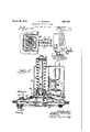
- Fig. 1 is a diagram used for explaining and the tension of the spring can be adjusted the ninethod; v by nut 14 threaded on the end of stud 12, Fig. 2 1s a. perspective vlew 'of a vacuum These parts are arranged in a suitable casing steam heating system arranged t0 WOrk C- 15 secured to the top of the casingK. Ayoke cording to my improvedmethod; 16 is pivoted to th ⁇ e casing 1 5 and is provid- Fig. 3 is a sectional elevation, actualsize, ed with studs 17-17 which connect the samev of the vacuum controller, v Y to the collarll. This yoke is extended out- Fig.
- chamber Q forms a differential diaphragmrhamber as the exposed area of Ny is larger than the exposed area of M, and that the chamber R for'ms la' differential diaphragm ⁇ chamber -as the exposed area of N is larger than the exposed area of O. It will also be noted that N minus M is much largen than N minus O.
- the operation canbe u nderstood by giving a specific illustration of the operation.
- My improved method distinguishes radically from this plan, because I rely additionally on a differential which varies according to the needs, so that more steam will be drawn into and through thefrdiators when Amore heat is needed and less ⁇ steam when less heat is needed.
- I v 1 The method of heating by steam, which consists inl'generating steam, expanding and condensing the 'steam' in radiators, ldrawing or helping the steam through the ,radiators by vacuum, increasing the steam pressure for more Vheat and 'at the same tune decreasing the vacuum a lesser /degree relatlvely to the increase of the steam i' essure to obtain a dif- ⁇ ferential vbetween the eam pressure and vacuum, which diferentialvvill increase as the steam pressure mcreases and the vacuum decreases.
- ⁇ las Y 2 The method of heating by steam, which consists in ,generating steam, expanding and condensing the ⁇ steam in radiators, drawing or helping the steam through the radiators by vacuum, ⁇ increasing or decreasing the steam pressure for more or less heat and at the same time decreasing or increasing the vacuum, a lesser degree relatively to the changes in the steam pressure, to obtain a differential between the steam pressure and vacuum which differential will increase as the steam pressure increases and the vacuum decreases and which differential will decrease as the steam pressure decreases and the vacuum increases.
- the method of heating by steam which consists in generating steam under sub-atmospheric pressure, expendingV and condensing the steam in radiators, drawing or helping the steam through the radiators by vacuum, increasing the steam pressure for more heat and at the same time decreasing the vacuum a lesser degree relatively to the increase of the steam pressure to obtain a dilerential between the steam pressure and vacuum, which differential will increase as the steam pressure increases and the vacuum decreases.
- the method of heating by steam which consists in generating steam under sub-atmospheric pressure, expanding and condensing the steam in radiators, drawing or helping the steam through the radiatorsby vacuum, increasing or decreasing the steam pressure for more or less heat and at the same time decreasing or increasing the vacuum a lesser degree relatively to the changes in the steam pressure to obtain a dierential between the steam pressure and vacuumwhich differential will increase or decrease as the steam pressure increases or decreases.
Landscapes
- Engineering & Computer Science (AREA)
- Physics & Mathematics (AREA)
- Thermal Sciences (AREA)
- Chemical & Material Sciences (AREA)
- Combustion & Propulsion (AREA)
- Mechanical Engineering (AREA)
- General Engineering & Computer Science (AREA)
- Jet Pumps And Other Pumps (AREA)
Description
March 29, 1932. l, C, JENMNGS 1,851,434
4 METHOD OF HEATING BY STEAM Filed Sept. l5, 1930 2 Sheets-Sheet. 1
METHOD OF HEATING BY STEAM Z 7. Q Filed Sept. l5, 1930 Patented-.Man 29,A v d I i l UNITED-STATES PATEN'I: OFFICE Application led September 15, 149.80. Serial-No. 481,825'.
This invention relates to an improved line 4-4 of Fig. 3, and Fig. 5jis a diagram method of heating by steam andhas especial showing the electric wiring. reference to vacuum steam heating. Referring to the drawings and' in detail, The term vacuum is used in this art to refer A designates the boiler, B the steam supply to sub-'atmospheric pressures or partial vacpipe, C one ofthe radiators, D the return 55 uums. line, and E the pumping apparatus of a vacu- In vacuum steam heating, steam is generum steam heating system. ated, and expanded and condensed in radia- The supply pipe B is provided with a valve tors, being drawn into and helped through V and a pressure regulator G. Thepumping 1U the radiators by vacuum. apparatus E illustratedis that shown in Re. 00
When more or less heat is needed, the' issue Patent No. 15,637 granted tome June steam pressure is increased or decreased, the 26, 1923 and consists of a receiving and sepvacuum remaining the same, whereby a varyarating tank H, in which the returns are reing steam differential is employed. ceived and the air and gas separated from,
1- As the flow of steam to and through the the condensate, anda pump which comprises 65 radiatorsdepends on this diierential, this a centrifugal water ump for returning the method of employing a varying diiferential condensate to the holler and a hydro-turbine has the advantage of causing more steam to air pump for creating and maintaining a -flow to and through the radiators when more vacuum in the return line and forcing the heat is needed and less steam to iiow when air and gas out ofthe system. ,I l 70 less heat is needed. But with this method The pump I is driven by an electric mOtOr of operation the differential is apt to become J, which motor is controlled by float and v so large, when the steam pressure is material-4 vacuum control, wired as Shown in Fig, 2 0r ly increased. as to cause objectionable nolse through a magneti@ starter as Shownin Fig, 5, 75
in the radiators. j The operation of this system and pump- To overcome'this dift'lculty and at the Same ing mechanism is well understood`and by ustlme retaln the advantages of a varylngpdlfing the Same, Steam under a vacuum 0r at felential, I decrease 01' increase the Yacllum a less than atmospheric pressure may be utilesser degree as the steam pressure is increased lized,
0 or decreased. y To practice my improved method, the vac- By thlS lmpI'OVed nl ei'fhO'd, amabla t0 muum controller is constructed as follows, refploy a differential, which varies dlrectly with erence being had to Figs 3 and l4h v changes in the .steam pressure but whlch AcasingKhas three diaphragms M, N,and IIeVCI Call bcqme 1500 gfeat- O1' 1n other OA arranged therein, the diaphragm's being 85 Wards, by '9h15 lmPlOVed mathodf I am able connected to move together by a spool or hub t0 PI'OPOI'OH the HOW t0 and t"hmimf'h the P. `Pins or studslO are attached to the hub radiators to changes in the steampressure, P and roect thi-0u h the Casin and are seand at Ithe same time avoid the diiiiculties cured i?, a] thrust cozlaflL g 40 before noted.4 A stud 12 is secured in the casing and the 90 l 'ThlS apparatus 1S Shfwn 1 n the accompany collar 11 is fitted to slide thereon. A sprin lng two sheets 0f draW1l1gS,1l1 Whlh 13 is arranged on stud 12 to bear on collar 11,
Fig. 1 is a diagram used for explaining and the tension of the spring can be adjusted the ninethod; v by nut 14 threaded on the end of stud 12, Fig. 2 1s a. perspective vlew 'of a vacuum These parts are arranged in a suitable casing steam heating system arranged t0 WOrk C- 15 secured to the top of the casingK. Ayoke cording to my improvedmethod; 16 is pivoted to th`e casing 1 5 and is provid- Fig. 3 is a sectional elevation, actualsize, ed with studs 17-17 which connect the samev of the vacuum controller, v Y to the collarll. This yoke is extended out- Fig. 4 is a sectional plan thereof on the wardly land forms the operating member of 100 an electric switch S secured to casing A15.' lThis switchis a snap switchof any approved construction and controls the circuit which extends to the electric motor J. As shown the. switch is closed, but if the diaphragms diaphragmsM and N by pipe 19. Thus the vacuum in the return line tends to lift diaphragm N, while vacuum in the supply line tends to pull the same down, but pressure in the supply tends to lift N.` 1
It will be noted that chamber Q forms a differential diaphragmrhamber as the exposed area of Ny is larger than the exposed area of M, and that the chamber R for'ms la' differential diaphragm^ chamber -as the exposed area of N is larger than the exposed area of O. It will also be noted that N minus M is much largen than N minus O.
The action of the diaphragms is repre-4 sented by theequation l c F [N (absolute pressure in R-absolute pressure in Q) +0 (atmospheric absolute absolute pressure in R)] -M (atmospheric absolute-absolute pressure i'n Q),
inwhich.F represents the upward force' exerted by the diaphragms and the term absolute is used to translate the partial vacuums and pressures into terms which will'elim-y inate the pressure of the atmosphere..
The operation canbe u nderstood by giving a specific illustration of the operation.
Assume that area of N minus area of M- is twice area of N minus area of O and that the maximum partial vacuum which the vac: uum pump vis designed for is twenty inches of ercury-or minus ten pounds per square inc `f The pumping mechanism is started in operation and the entire system is placedl under vacuum until the switch opens. Now suppose steam is generated and that the same decreases the vacuum" in the supply and in R one inch or one-half pound and'also assume that when. the supplyfand R are at nine'- teen inches, F. will open the switch. This givesa steam differential `of an inch or onehalf pound as represented at the left of Fig. 1. This small differential` will just about cause the steam to circulate.
Now suppose the steam pressure is raised vsix pounds from the assumed minimum which lcan be done by generating more steam in the boiler, manipulating` .valve V or adjusting pressure regulator G.
v This will give a six inch` or three pound steam differential as indicated inthe middle of the diagram, Fig. 1, thusv giving the de- `sird1 ratio of increase of the steam differen 1a This ratio will continue even if the steam pressureV is increased above atmospheric pressure. v y
For` example, if the steam pressure 'should be increased twelve pounds from the assumed minimum, to two pounds above atmospheric pressure, the vacuum needed in Q, to open the switch will` be reduced to eight inches or four pounds,as shown at the right in FigQl, giving a twelve inch or six 'pound steam differential.
From this, it will be seen I am able to obtain a differential between the supply pressure and return pressure which increases as the steam pressure increases but with a decreasing vacuum, and which decreases as the steam pressure decreases but with an increasing vacuum. Thus I am able` to obtain the advantages before noted. d
The figures andratios above assumed are for the-purpose of explanation and will be varied and Ydeparted from to meet the ex` igencies of any particular installation without departing from my invention.
I am aware that in operating vacuumsteam heating systems, the vacuum has been decreased or increased to the same degree that the steam pressure has `been .increased or decreased, so as to obtain a substantially constant differential. As the flow to and through the radiators depends on the differential, by this plan variance in the pressure or temperature of the steam alone is .depended upon for heat variation. f
My improved method distinguishes radically from this plan, because I rely additionally on a differential which varies according to the needs, so that more steam will be drawn into and through thefrdiators when Amore heat is needed and less `steam when less heat is needed.
The details and steps herein described may pursuance of a requirement of the Patent Office.
hat I claimand desire to secure by Letters atent is I v 1. The method of heating by steam, which consists inl'generating steam, expanding and condensing the 'steam' in radiators, ldrawing or helping the steam through the ,radiators by vacuum, increasing the steam pressure for more Vheat and 'at the same tune decreasing the vacuum a lesser /degree relatlvely to the increase of the steam i' essure to obtain a dif-` ferential vbetween the eam pressure and vacuum, which diferentialvvill increase as the steam pressure mcreases and the vacuum decreases. t
Having thus fully described my invention,
`las Y 2. The method of heating by steam, which consists in ,generating steam, expanding and condensing the` steam in radiators, drawing or helping the steam through the radiators by vacuum,` increasing or decreasing the steam pressure for more or less heat and at the same time decreasing or increasing the vacuum, a lesser degree relatively to the changes in the steam pressure, to obtain a differential between the steam pressure and vacuum which differential will increase as the steam pressure increases and the vacuum decreases and which differential will decrease as the steam pressure decreases and the vacuum increases.
3. The method of heating by steam, which consists in generating steam under sub-atmospheric pressure, expendingV and condensing the steam in radiators, drawing or helping the steam through the radiators by vacuum, increasing the steam pressure for more heat and at the same time decreasing the vacuum a lesser degree relatively to the increase of the steam pressure to obtain a dilerential between the steam pressure and vacuum, which differential will increase as the steam pressure increases and the vacuum decreases.
4. The method of heating by steam, which consists in generating steam under sub-atmospheric pressure, expanding and condensing the steam in radiators, drawing or helping the steam through the radiatorsby vacuum, increasing or decreasing the steam pressure for more or less heat and at the same time decreasing or increasing the vacuum a lesser degree relatively to the changes in the steam pressure to obtain a dierential between the steam pressure and vacuumwhich differential will increase or decrease as the steam pressure increases or decreases.
In testimony whereof I have hereunto affixed my signature.
` `IRVING C. JENNINGS.
Priority Applications (2)
| Application Number | Priority Date | Filing Date | Title |
|---|---|---|---|
| US481825A US1851434A (en) | 1930-09-15 | 1930-09-15 | Method of heating by steam |
| US589014A US2065704A (en) | 1930-09-15 | 1932-01-26 | Vacuum steam heating apparatus |
Applications Claiming Priority (1)
| Application Number | Priority Date | Filing Date | Title |
|---|---|---|---|
| US481825A US1851434A (en) | 1930-09-15 | 1930-09-15 | Method of heating by steam |
Publications (1)
| Publication Number | Publication Date |
|---|---|
| US1851434A true US1851434A (en) | 1932-03-29 |
Family
ID=23913530
Family Applications (1)
| Application Number | Title | Priority Date | Filing Date |
|---|---|---|---|
| US481825A Expired - Lifetime US1851434A (en) | 1930-09-15 | 1930-09-15 | Method of heating by steam |
Country Status (1)
| Country | Link |
|---|---|
| US (1) | US1851434A (en) |
-
1930
- 1930-09-15 US US481825A patent/US1851434A/en not_active Expired - Lifetime
Similar Documents
| Publication | Publication Date | Title |
|---|---|---|
| US1851434A (en) | Method of heating by steam | |
| US2065704A (en) | Vacuum steam heating apparatus | |
| US2312191A (en) | Steam heating system | |
| US2003585A (en) | Method and apparatus for heating with steam | |
| US1951588A (en) | Heating system | |
| US2217087A (en) | Steam heating system | |
| US1869696A (en) | Turbine and motor driving mechanism for rotary pumps | |
| GB381817A (en) | Turbine and motor driving mechanism for rotary pumps used in steam heating systems | |
| US2468268A (en) | Heating system | |
| US2742233A (en) | Heating system | |
| US1875957A (en) | Temperature control mechanism for heating systems | |
| US1828302A (en) | Vacuum heating system | |
| US2103178A (en) | Steam heating system and method of supplying steam to the radiators thereof | |
| US2140701A (en) | Control mechanism for steam heating systems | |
| US822184A (en) | Pump-regulating system. | |
| US1977303A (en) | Steam heating system | |
| US2312192A (en) | Steam heating method | |
| US1783428A (en) | Pressure-control mechanism for vacuum heating systems | |
| US1999040A (en) | Heating system | |
| GB332747A (en) | Improvements in steam heating apparatus | |
| US2344874A (en) | Steam heating system | |
| US2022904A (en) | Vacuum pump | |
| US1024547A (en) | Boyers | |
| US2314524A (en) | Cooling system | |
| US2282014A (en) | Control means for vacuum heating systems |