US1851424A - Pavement covering and uncovering machine - Google Patents
Pavement covering and uncovering machine Download PDFInfo
- Publication number
- US1851424A US1851424A US460916A US46091630A US1851424A US 1851424 A US1851424 A US 1851424A US 460916 A US460916 A US 460916A US 46091630 A US46091630 A US 46091630A US 1851424 A US1851424 A US 1851424A
- Authority
- US
- United States
- Prior art keywords
- earth
- pavement
- frame
- conveyors
- framework
- Prior art date
- Legal status (The legal status is an assumption and is not a legal conclusion. Google has not performed a legal analysis and makes no representation as to the accuracy of the status listed.)
- Expired - Lifetime
Links
- 238000009499 grossing Methods 0.000 description 26
- 238000000151 deposition Methods 0.000 description 6
- 230000002441 reversible effect Effects 0.000 description 5
- 239000000969 carrier Substances 0.000 description 4
- 238000010276 construction Methods 0.000 description 4
- XLYOFNOQVPJJNP-UHFFFAOYSA-N water Substances O XLYOFNOQVPJJNP-UHFFFAOYSA-N 0.000 description 4
- 230000033001 locomotion Effects 0.000 description 3
- 230000005540 biological transmission Effects 0.000 description 2
- 230000003028 elevating effect Effects 0.000 description 2
- 235000011194 food seasoning agent Nutrition 0.000 description 2
- 238000009736 wetting Methods 0.000 description 2
- 238000007599 discharging Methods 0.000 description 1
- 239000000463 material Substances 0.000 description 1
- 238000007665 sagging Methods 0.000 description 1
- 238000005406 washing Methods 0.000 description 1
Images

Classifications
-
- E—FIXED CONSTRUCTIONS
- E01—CONSTRUCTION OF ROADS, RAILWAYS, OR BRIDGES
- E01C—CONSTRUCTION OF, OR SURFACES FOR, ROADS, SPORTS GROUNDS, OR THE LIKE; MACHINES OR AUXILIARY TOOLS FOR CONSTRUCTION OR REPAIR
- E01C23/00—Auxiliary devices or arrangements for constructing, repairing, reconditioning, or taking-up road or like surfaces
- E01C23/03—Arrangements for curing paving; Devices for applying curing means; Devices for laying prefabricated underlay, e.g. sheets, membranes; Protecting paving under construction or while curing, e.g. use of tents
Definitions
- the invention relates primarily to a machine for covering green concrete highways with earth to season the concrete, and for removing the earth after it has been left in dampened condition upon the pavement for the proper time, the principal object of the invention being to provide a rather simple, yet a highly advantageous mobile machine for these or analogous purposes.
- the concrete is customarily poured and finished between parallel side forms which remain in place until the material has hardened, and a further object is to provide a novel machine which travels upon these side forms as tracks and hence places no strain upon the concrete with danger of injuring same prior to complete hardening.
- Another object of the invention is the provision of a machine which will drag earth inwardly from one or both sides of the highway, and thoroughly spread it over the concrete, and which will later drag the earth from the seasoned concrete and spread it along one or both sides of the highway.
- Yet another aim is to make novel provision whereby the machine forms ridges of earth along opposite edges of the pavement to retain the water used for wetting the earth covering.
- concrete highways are often formed with curbs to prevent lateral running of water and washing away of the earth shoulders along the road, the water being guided from the pavement at the bottoms of the hills by appropriate spillways or the like. Then too. concrete highways are either constructed with no crown or with crowns of different pitch. and further objects are to provide'a machine which may be readily adjusted to cope with such conditions as these.
- Yet another aim is the provision of a machine which may be successfully used for dragging earth from either side of a highway and depositing it at the other side, for ipstance, when forming the usual earth shoulc ers.
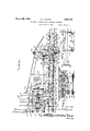
- Fig. 1 is a top plan View of substantially one-half of the machine, the remainder being formed by mere duplicates of features shown on said one-half.
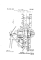
- Fig. 2 is a vertical sectional view substantially on line 2-2 of Fig. 1.
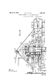
- Figs. 3 and 4 are enlarged vertical sectional views on lines 3-3 and 4-4 of Fig. 1.
- Fig. 5 is a vertical transverse sectional view on line 55 of Fig. 2.
- Fig. 6 is a horizontal sectional view on line 66 of Fig. 2.
- Fig. 7 is a perspective view showing one of the shield plates which prevent depositing of earth upon the side forms, illustrating also the means at one end of the shield plates to form a ridge for water-retaining purposes.
- the frame of the machine is elongated transversely of the line of travel, said frame embodying front and rear side bars 10 which are preferably transversely cut at 11 and bolted at 12 to splice plates such as 13 (Fig. 2), there being a sufficient number of bolt holes 14 to permit varying the lengths of the bars 10 according to the width of the pavement over which the machine is to operate.
- the bars 10 are rigidly connected by transverse bars, most of which are denoted at 15, while other transverse bars 16 extend between and are rigidly secured to said bars 10 between the central and the end portions of the latter.
- end bars 17 are disposed, being preferably formed of channel beams, as shown for instance in Figs. 3 and 4.
- end bars 17 are'rigidly secured upon short provided with flat outer faces disposed in a common vertical plane as seen most clearly in Fig. 4.
- guide plates which may well be formed by secur ing short channels 20 and 21 together, one upon the other, the lower channels 21 being rigidly secured at 22 to the front and rear bars 10.
- the webs of these bars 10 project beyond the plates 2021, as denoted at 23, and curved vertically disposed angle bars 24 are secured by bolts 25 against opposite sides of said webs, said bars 24 being provided with vertically spaced bolt holes 26 allowing vertical adjustment of said bars.
- Crown plates 27 are rigidly secured upon the ends of the bars 17 and upon the opposed portions of the channel bars 20, said crown plates being provided with fixed nuts 28 through which vertical screws 29 are threaded. The lower ends of these screws are swiveled at 30 to the upper ends of arched yokes 31 which contacts slidably with the inner sides of the members 17, 18, 20 and 21. said yokes being held against forward and rearward tilting by guide bars 32 secured to said members 17, 18, 20 and 21.
- the lower ends of the inner and outer legs of the yokes 31, are provided with bearings 33 in which short axles 34 are rotatably mounted, said axles being provided with wheels 35 of flanged form, to travel upon the usual side forms F of a concrete pavement C, or to travel upon auxiliary forms F temporarily mounted upon the forms F as shown in Fig. 4.
- the forms F are used only when a curb C (Fig. 4) is to be formed along the pavement for drainage purposes.
- the wheels 35 are driven to move the machine along the highway in either direction, and by properly adjusting the screws 29, the entire frame may be raised or lowered to the required extent.
- a wheel-driving shaft 36 Parallel with and above one of the bars 10, is a wheel-driving shaft 36 whose ends are mounted in bearings 37 secured to the ends of the bars 17, said shaft 36 being extensible and retractible in any desired way, according to any adjustments which may be made at 11 and 12.
- the shaft 36 drives the axles 34 on the wheels 35, and a clutch 41 (Fig. 1) is preferably employed to allow relative movement of the wheels at either side of the machine with respect to those at the other side. whenever necessary, for ins ance when turning corners or if one side of the machine should from any cause have a tendency to lag behind the other side.
- the chains 39 are inclined and they will compensate for the necessary relative Vertical movement of frame and wheels when raising or lowering the forrrier, appropriate tighteners 42 (Fig. 4) being provided for said chains.
- a motor 43 is suitably mounted upon the frame and by means of a chain 44 drives a shaft 45.
- This shaft 45 through the instrumentality of an appropriate reverse gear 46 controlled by a lever 47, drives a variable speed transmission 48.
- the shaft 49 driven by this transmission drives gearing within the casing 50 1) and this gearing drives the shaft 36.
- Each of these conveying means embodies an inner horizontal, endless conveyor 51 extending from the central portion of the frame to a point slightly inward of the longitudinal edge of the pavement as seen most clearly in Fig. 2, and an outer vertically swingable conveyor 52.
- the endless portions of these conveyors are formed by chains trained around sprockets,suitableearth-dragging cleats 53 being secured to said chains.
- the inner shafts of the conveyors 51 are denoted at 54 and 54.
- the outer shaft of one of the conveyors 51 is shown at 55
- the inner shaft of one of the conveyors 52 is denoted at 56
- the outer shaft of this conveyor is shown at 57 in Fig. 4.
- the bearings of the two shafts are adjustable both vertically and horizontally. These bearings are denoted at 58 (Fig. 4), and by means of vertical slots 59 and bolts 60, they are mounted upon vertical plates 61, these plates being connected by bolts 62 and slots 63 with the side bars 10. Adjusting screws 64 are provided to force the plates 61 toward the ends of these bars 10 to tighten the chains of the conveyors 51.
- These conveyors 51 must be adjusted further downward from the frame when earth is to be spread upon or removed from a pavement having a curb C" (Fig. 4). and the outer ends of said conveyors must be adjusted either inwardly or outwardly until their shafts 55 come directly over the inner edges E of the curbs.
- the mounting means above described for the shafts 55 readily permit these adjustments.
- Each shaft 56 is mounted in bearings 65 secured by bolts 66 to the curved vertical bars 24 above described, these bars being in eccentric relation with shaft 55 for a purpose to appear vertically spaced bolt holes 67 are provided in the bars 24 allowing adjustment of the bearings 65 vertically along said bars. Then too, it will be remembered that the bars themselves are vertically adjustable by means of the bolts and the bolt holes 26. Hence, the inner ends of the conveyors 52 may be vertically adjusted with respect to the main 4;
- ROADS Aa--lD PAVEMENTS frame of the machine as occasion may demand.
- the inner shafts 56 of these conveyors serve as pivotal supports for vertically swingable bars 68 which carry the outer shafts 57 of said conveyors.
- a suitable number of rollers 69 are mounted on brackets 70 carried by the bars 68.
- additional rollers such. as 71 are provided. These rollers may be mounted at one end on a scraper plate 7 3, and at their other ends carried by brackets 72 secured to the bars 68.
- One of these bars at each side of the machine may carry a scraper plate 7 3 while near the other bar 68, there is preferably mounted an earth-loosening, spiked drum 74 (Fig. 1), said drum being driven by gearing 75 from the shaft 56.
- the plate 73 holds loose earth within the range of the earthdragging cleats 53 so that these cleats will inwardly drag such earth.
- Each shaft 56 is driven from the adjacent shaft 55 by means of a chain 76, and the shafts 54 and 54 of the inner conveyors 51 are driven by means below described, reference being made more particularly to Fig. 6. Loosening or tightening of the chain 76 during vertical adjustment of shaft 56, is prevented by the concentric relation of the bars 24 with the shaft 55.
- Gear 77 meshes with an idler 79 driven by a pinion 80, and this pinion also meshes with a gear 81 secured upon the shaft 54.
- a sprocket 82 is also secured upon this shaft 54, and a chain 83 connects this sprocket with the sprocket 78.
- a shiftable clutch 84 controlled by a lever 85 is provided for connecting either the gear 77 or the sprocket 78 with the shaft 54. It will be seen that gear 77 always travels oppositely from gear 81, whereas sprocket 78 always travels in the same direction as shaft 54 on which gear 81 is secured.
- both shafts 54 and 54 will be driven in the same direction, and this direction may be toward either end of the machine, due to reversible driving means hereinafter described for the pinion 80.
- ⁇ Vhen clutch 84 is engaged with gear 77 however, the two shafts 54 and 54' will be driven in opposite directions to either drive the conveyors toward opposite ends of the machine or toward the center of said machine from its opposite ends.
- Pinion is secured upon a short shaft 86 having a sprocket 87 at one end, this sprocket being driven by a chain 88 (Figs. 1, 2 and 6) from another sprocket on a frame-carried shaft 89.
- Shaft 89 is driven from the shaft 45 by means of a reverse gear 90 controlled by a lever 91.
- pinon 80 may be driven in one direction or the other, and by means of the clutch 84, it is insured that the conveyors at the righthand side of the machine may be driven in the same direction as those at the left-hand side thereof, (either toward the right or to ward the left), and that the conveying means at the right-hand side of the machine may be driven reversely from those at the left-hand side thereof if desired.
- the conveying means 52-51 at the opposite sides of the machine may be used for drawing earth inwardly and spreading it over the pavement; later these conveyors may be driven to carry the earth outwardly from the pavement and distribute it along a side or sides of the same, and if desired, all of the conveyors may be driven in the same direction to carry earth from one side of the highway entirely across the latter, discharging it at the other side.
- Shield plates 92 are provided to overlie the side forms F or F, between the wheels preventing the conveyors from deposit ing earth upon said forms at the gaps between the inner ends of the lateral conveyors 52 and the outer ends of the conveyors 51.
- each shield plate 92 is provided with oblique means 93 for inwardly throwing earth to form a water-retaining ridge 94 along an edge of the pavement (Fig. 1).
- the shield plates 92 are connected by hangers 95 with the bearings 33 of the wheels 35 so that they always remain in fixed relation with the side forms of the pavement.
- a central plate 96 (Figs. 1 and 2) which is preferably detachably mounted, is positioned between the inner ends of the conveyors 51 for the purpose of guiding earth from one of these conveyors to the other when they are both driven in the same direction for carrying earth entirely across the roadway.
- a vertical plate 97 at one end of the plate 96 also serves to prevent earth from falling into the path along which the sprocket 87 must travel.
- Longitudinally springable tracks 98 are provided to properly guide the lower reaches of the conveyors 51.
- the cleats 53 of each of these conveyors being provided with lugs 99 which slide along said tracks.
- One of these tracks is connected by vertically adjustable brackets 100 (Figs. 5) with one of the bars 10.
- the other track 98 is carried by adjusting screws 101 which extend downwardly from the bars 16 above described.
- the conveying means 51 may be bowed into conformity with any crown which the concrete pavement may possess, or adjustment may be made for a roadway having no crown. Vhen extending or retracting the bars 10 for different widths of highways, it is necessary to disconnect one end of some of the hangers or the like 100 and 101, later reconnecting them in other openings. It is also of course necessaryto remove links from or add them to the conveyors 51.
- Chains 102 are shown connected with the bars 68, the upper ends of said chains being wound upon suitably supported shafts or reels 103.
- 104 denotes shafts for effecting rotation of the reels 103 in either direction.
- a rotary beater 105 on the shaft 55 at one side of the conveyor 51.
- This conveyor throws some of the earth falling inwardly from the shield plate 92 into the path of conveyor 51, when the machine is used for covering the pavement Similarly, when uncovering, the beater 105 throws the earth discharged at the outer end of the conveyor 51 across the shield plate 92 so that it will be received by the adjacent outer conveyor 52.
- the rapid motion of the conveyors at the 0pposite sides of the shield plate 92 and at opposite sides of the guide 96 also assists in causing earth to travel across these members.
- a V-point 106 is preferably provided at one end of the member 96 so that when uncovering a pavement, this V-point will direct the earth along the center of said pavement into the zones over which the conveyors 51 operate, so that such earth will be carried off with the rest by the conveyors.
- the machine is driven in the direction of the arrow A (Fig. 1). Then, the spiked drums 74 loosen the earth along opposite sides of the highway, the conveyors 52 drag this earth inwardly and throw most of it across the shield plates 92, and this earth is further moved inwardly by the inner conveyors 51, which spread it uniformly over the surface of the pavement, the member 96 being then preferably removed. If necessary, the conveyors may be so driven as to move earth inwardly from one side only of the roadway and spread it over the surface of the latter, or said conveyors may be so driven as to draw earth inwardly from one side of the highway, carry it entirely across the latter and discharge it onto the other side.
- the machine As the machine progresses in covering, it leaves the ridges 91 along opposite edges of the pavement and these ridges are instrumental in retaining the water used for wetting the covering earth throughout the period during which the concrete is seasoning. After such seasoning, the same machine may be used for uncovering. Then, it is driven in the direction of the arrow B (Fig. 1) and the conveyors are so driven as to carry off the earth to one or both sides of the roadway, as may be required.
- a pavement covering and uncovering machine comprising a mobile frame adapted for advancement along a pavement; earthdragging conveying means mounted on one half of said frame and embodying a horizon tal inner portion adapted to extend from one longitudinal edge of the pavement to the central portion thereof, and an outer portion adapted to project laterally from the pavement; additional conveying means substantially duplicating the aforesaid conveying means and mounted on the other half of said frame, and selective means for driving the two conveying means simultaneously toward either edge of the pavement, for driving said two conveying means simultaneously toward opposite edges of the pavement, or for driving said two conveying means simultaneously toward the center of the pavement.
- a mobile frame right and left earth-drag ing conveying means mounted on said frame and extending outwardly from the central portion thereof, said conveying means having separate parallel drive shafts at their inner ends, two wheels loose upon one of said shafts, reversible driving means for driving the other shaft in either direction and for driving one of said loose wheels oppositely from said other shaft, driving connections between said other shaft and the other of said loose wheels for driving the latter unidirectionally with the former, and clutch means for connecting either of said loose wheels with said one shaft.
- each of said conveying means being formed of two separate conveyors constituting said horizontal and verticallv swingable portions respectively, earth-guiding plates carried by the frame between said separate conveyors, and a central earth-guiding plate between the inner ends of the inner horizontal conveyors,
- said plates serving to guide earth from each conveying means mounted on said frame and adaptedito draw earth across the pavement and over said side form, and a shield plate carried by the frame between said front and rear wheels thereof, said plate being positioned to prevent said conveying means from depositing earth upon said side form.
- a frame to overlie a pavement, a front and a rear wheel adapted to travel along a pavement side form, bearings for said wheels and means supporting said frame upon said bearings for vertical adjustment,conveyingmeans mounted on said frame and adapted to draw earth across the pavement and over said side form, a shield plate extending between said wheels and positioned to overlie said side form, thereby preventing said conveying means from depositing earth on said side form, and attaching means for said shield late secured to the latter and secured to said earings.
- a frame to overlie a pavement said frame having a front and a rear wheel to travel along a pavement side form, a horizontal earthdragging conveyor mounted on said frame for moving earth across the pavement, a vertically swingable earth-dragging conveyor mounted on the frame and adapted to project laterally from the pavement, the inner ends of the two conveyors being spaced apart horizontally, and a shield plate under the space between said conveyors, said shield plate extending between said front and rear wheels in position to overlie said side form, thereby preventing said conveyors from depositing earth upon said form.
- a mobile frame adapted for advancement along a pavement
- earth-dragging conveying means mounted on said frame and embodying a h0rizontal portion for disposition over the pavement and an outer portion to project laterally from said pavement, and adjustable means for longitudinally bowing said horizontal portion of said conveying means in conformity with any existing crown of the pavement.
- a mobile frame adapted for advancement along a pavement, an endless earth-dragging con veyor mounted on said frame and adapted to txaminer drag earth transversely of the pavement, supporting tracks for the lower reach of said conveyor, and adjustable means mounting said tracks on said frame and adapted for bowing said tracks into conformity with any existing crown of the pavement.
- a frame adapted for advancement along a pavement, said frame having front and rear wheels adapted to travel upon a pavement side form, an earth-dragging conveyor mounted on said frame for dragging earth transvezseiy of the pavement, the outer end of said conveyor being disposed for inward spacing from said side form, means for adjusting said outer conveyor end vertically with respect to said frame, and means for horizontally adjusting said outer conveyor end to vary its inwardly spaced relation with said side form.
- a mobile frame adapted for advancement along a pavement and having wheels to travel on pavement side forms, pavement covering and uncovering means embodying a horizontal pavement-overlying portion and a drag conveyor, the latter extending laterally from one end of said frame, means mounting said conveyor upon the frame for vertical adjustment and vertical swinging, and means for vertically swinging said conveyor.
- a mobile frame adapted for advancement along a pavement and having wheels to travel on pavement side forms, a drag conveyor disposed horizontally in position to travel transversely of the pavement, said conveyor embodying a rotary shaft at one end of the frame, a second drag conveyor extendin laterally from said end of said frame, sai sec-- ond conveyor embodying a second shaft at its inner end parallel with and spaced outwardly from the first named shaft, driving connections extending between said shafts, bearings in which said second shaft is mounted to allow vertical swinging of the second conveyor, fixed arcuate vertical bars secured to said frame in eccentric relation with the first named shaft, means mounting said bearings on said vertical arcuate bars for vertical adjustment, and means for vertically swinging said conveyor.
- a machine for covering a concrete pavement with earth comprising a mobile frame adapted for advancement along the pavement, and earth conveying means mounted on said frame and embodying one portion positioned to extend laterally beyond the pavement for inwardly drawing earth, said conveying means embodying another portion adapted to spread the inwardly drawn earth over the pavement.
- a machine for covering a concrete pavement with earth comprising a mobile frame adapted for advancement along the pavement, and earth conveying means mounted on said frame and embodying one portion positioned to extend laterally beyond the pavement for inwardly drawing earth, said conveying means embodying another portion adapted to spread the inwardly drawn earth over the pavement and to leave a water-retaining ridge of earth upon an edge portion of the pavement.
- a machine for covering a concrete pavement with earth comprising a mobile frame adapted for advancement along the pavement, two vertically swingable drag conveyors mounted on said frame and positioned to extend laterally beyond the pavement, said conveyors being adapted to drag earth inwardly onto the pavement, two additional drag conveyors horizontally mounted on said frame in position to spread the inwardly drawn earth over the pavement, and means for driving said conveyors, the outer ends of said additional conveyors being inwardly spaced from the inner ends of the first named conveyors to leave water-retaining ridges of earth upon the edge portions of the pavement.
- Apparatus of the character described including a main framework, carrier wheels on which the framework is mounted, a motor on the framework, driving connections between the motor and some of the carrier wheels, sid'e frames pivotally connected to the respective ends of the frame, side conveying aprons in said side frames, smoothing aprons in the main framework, and means operatively connecting the motor with said conveying and smoothing aprons and effective to simultaneously drive said aprons.
- Apparatus of the character described including a framework, carrier wheels on which the framework is mounted, a motor on the framework, driving connections between the motor and some of said wheels, a smoothing apron movable transversely with respect to the framework, and having means adapted to distribute loose earth, a side frame attached to the framework, and a conveying apron in said side frame having means adapted to convey loose earth into the range of said smoothing apron.
- Apparatus of the character described including a framework, carrier wheels on which the framework is mounted, a motor on the framework, driving connections between the motor and some of said wheels, a smoothing apron movable transversely with respect to the framework and having means adapted to distribute loose earth, a side frame attached to the framework, a conveying apron in said side frame having means adapted to convey loose earth into the range of said smoothing apron, and operating connections through which said aprons are driven from said motor.
- Apparatus of the character described including a framework, carrier wheels on which the framework is mounted, a motor on the framework, driving connections between the motor and some of said wheels, a smoothing apron movable transversely with respect to the framework and having means adapted to distribute loose earth, a side frame attached to the framework, a conveying apron in said side frame having means adapted to convey loose earth into the range of said smoothing apron, the adjacent ends of said aprons being spaced apart, and a de fiector disposed behind the space between said aprons.
- An apparatus for delivering loose earth from the sides of paved roadway onto and for distributing the earth over the paving said apparatus including a framework, carriers on which said framework is mounted smoothing aprons mounted in the framework and movable transversely of the paving and having earth conveying and smoothing means, side frames pivoted to and extending out laterally from the framework, a conveying apron mounted in each side frame and having means for delivering said loose earth onto the paving within the range of said smoothing aprons, and means on the framework for driving said conveyors.
- Apparatus of the character described including a framework, carrier wheels on which the framework is mounted, a motor on the framework, driving connections between the motor and some of said wheels, a smoothing apron movable transversely with respect to the framework and having means adapted to distribute loose earth, a side frame attached to the framework, a conveying apron in said side frame having means adapted to convey loose earth into the range of said smoothing apron, and means for elevating and lowering said side frame and for fixing it at a selected position.
- An apparatus for delivering loose earth from the sides of a paved roadway onto and for distributing the earth over the paving said apparatus including a framework, carriers on which said framework is mounted, smoothing aprons mounted in the framework and movable transversely of the paving and having earth conveying and smoothing means, side frames pivoted to and extending laterally from the framework, a conveying apron mounted in each side frame and having means for delivering said loose earth onto the paving within the range of said smoothing aprons, means on the framework for driving said conveyors, and means for elevating and lowering said side frames and for fixing said side frames at selected positions.
- An apparatus for delivering loose earth from the sides of a paved roadway onto and for distributing the earth over the paving said apparatus including a framework, carriers on which said framework is mounted, smoothing aprons mounted in the framework and movable transversely of the paving and having earth conveying and smoothing means, side frames pivoted to and extend ing out laterally from the framework, a conveying apron mounted in each side frame and having means for delivering said loose earth onto the paving within the range of said smoothing aprons, and means on the frame work for driving said conveyors, the adjacent ends of the conveying aprons and the corresponding smoothing aprons being spaced apart.
- An apparatus for delivering loose earth from the sides of a paved roadway onto and for distributing the earth over the paving said apparatus including a framework, carriers on which said framework is mounted, smoothing aprons mounted in the framework and movable transversely of the paving and having earth conveying and smoothing means, side frames pivoted to and extending out laterally from the framework, a conveying apron mounted in each side frame andhaving means for delivering said loose earth onto the paving within the range of said smoothing aprons, means on the framework for driving said conveyors, the adjacent ends of the conveying aprons and the corresponding smoothing aprons being spaced apart, and deflectors behind the spaces between said adjacent ends of said aprons disposed to throw the earth in front of them inwardly.
- Apparatus of the character descrlbed for distributing loose earth adjacent a roadway across the roadway paving including a smoothing apron movable transversely across the paving, and a side conveying apron movable transversely with respect to said paving and disposed to one side of the paving, each apron embodying means adapted to engage and move said earth.
- Apparatus of the character described for distributing earth adjacent a roadway across the roadway paving including a smoothing apron movable transversely across the paving, a side conveying apron movable transversely with respect to said paving and disposed to one side of the paving, each-apron embodying means adapted to engage and move said earth, and means in front of the side apron for breaking up hard earth in front of said side apron.
Landscapes
- Engineering & Computer Science (AREA)
- Architecture (AREA)
- Civil Engineering (AREA)
- Structural Engineering (AREA)
- Road Paving Machines (AREA)
Description
March 29, 1932.- B H. FLYNN PAVEMENT COVERING AND UNCOVERING MACHINE Filed June 15, 1950 4 SheetsSheet 1 Witvmoo VeA flttommao March 29, 1932 B. H. FLYNN PAVEMENT COVERING AND UNCOVERING MACHINE Filed June 13 1950 7 42 a D U a 4 SheetsSheet 2 March 29, B FLYNN 1,851,424
PAVEMENT COVERING AND UNCOVERING MACHINE Filed June 13, 1930 4 Sheets-Sheet 3 March 29, 1932. B. H. FLYNN PAVEMENT COVERING AND UNCOVERING MACHINE Fi led June 15, 1930 4 SheetsSheet 4 ||VHU Ariu PAVtMtN FS Patented Mar. 29, 1932 UNITED STATES BENJAMIN H. FLYNN,
LXamlTlE PATENT OFFICE OF AMARILLO, TEXAS PAVEMENT COVERING AND UNCOVERING MACHINE Application filed June 13,
This application is a continuation in part of my pending U. S. application, Serial N 0. 403,798, filed August 31, 1929.
The invention relates primarily to a machine for covering green concrete highways with earth to season the concrete, and for removing the earth after it has been left in dampened condition upon the pavement for the proper time, the principal object of the invention being to provide a rather simple, yet a highly advantageous mobile machine for these or analogous purposes.
The concrete is customarily poured and finished between parallel side forms which remain in place until the material has hardened, and a further object is to provide a novel machine which travels upon these side forms as tracks and hence places no strain upon the concrete with danger of injuring same prior to complete hardening.
Another object of the invention is the provision of a machine which will drag earth inwardly from one or both sides of the highway, and thoroughly spread it over the concrete, and which will later drag the earth from the seasoned concrete and spread it along one or both sides of the highway.
Yet another aim is to make novel provision whereby the machine forms ridges of earth along opposite edges of the pavement to retain the water used for wetting the earth covering.
On hills, concrete highways are often formed with curbs to prevent lateral running of water and washing away of the earth shoulders along the road, the water being guided from the pavement at the bottoms of the hills by appropriate spillways or the like. Then too. concrete highways are either constructed with no crown or with crowns of different pitch. and further objects are to provide'a machine which may be readily adjusted to cope with such conditions as these.
Yet another aim is the provision of a machine which may be successfully used for dragging earth from either side of a highway and depositing it at the other side, for ipstance, when forming the usual earth shoulc ers.
With the foregoing and minor objects in 1930. Serial No. 460,916.
view, becoming apparent as the description proceeds, the invention resides in the novel subject matter hereinafter described and claimed, description being accomplished by reference to the accompanying drawings.
Fig. 1 is a top plan View of substantially one-half of the machine, the remainder being formed by mere duplicates of features shown on said one-half.
Fig. 2 is a vertical sectional view substantially on line 2-2 of Fig. 1.
Figs. 3 and 4 are enlarged vertical sectional views on lines 3-3 and 4-4 of Fig. 1.
Fig. 5 is a vertical transverse sectional view on line 55 of Fig. 2.
Fig. 6 is a horizontal sectional view on line 66 of Fig. 2.
Fig. 7 is a perspective view showing one of the shield plates which prevent depositing of earth upon the side forms, illustrating also the means at one end of the shield plates to form a ridge for water-retaining purposes.
The preferred construction has been illustrated and while such construction will be specifically explained, it is to be understood that within the scope of the invention as claimed, numerous variations may be made.
The frame of the machine is elongated transversely of the line of travel, said frame embodying front and rear side bars 10 which are preferably transversely cut at 11 and bolted at 12 to splice plates such as 13 (Fig. 2), there being a sufficient number of bolt holes 14 to permit varying the lengths of the bars 10 according to the width of the pavement over which the machine is to operate. At various locations, the bars 10 are rigidly connected by transverse bars, most of which are denoted at 15, while other transverse bars 16 extend between and are rigidly secured to said bars 10 between the central and the end portions of the latter. Over the ends of the bars 10, end bars 17 are disposed, being preferably formed of channel beams, as shown for instance in Figs. 3 and 4. These end bars 17 are'rigidly secured upon short provided with flat outer faces disposed in a common vertical plane as seen most clearly in Fig. 4. Spaced outwardly from the bars 17' and 18 and parallel therewith, are guide plates which may well be formed by secur ing short channels 20 and 21 together, one upon the other, the lower channels 21 being rigidly secured at 22 to the front and rear bars 10. The webs of these bars 10 project beyond the plates 2021, as denoted at 23, and curved vertically disposed angle bars 24 are secured by bolts 25 against opposite sides of said webs, said bars 24 being provided with vertically spaced bolt holes 26 allowing vertical adjustment of said bars.
Crown plates 27 are rigidly secured upon the ends of the bars 17 and upon the opposed portions of the channel bars 20, said crown plates being provided with fixed nuts 28 through which vertical screws 29 are threaded. The lower ends of these screws are swiveled at 30 to the upper ends of arched yokes 31 which contacts slidably with the inner sides of the members 17, 18, 20 and 21. said yokes being held against forward and rearward tilting by guide bars 32 secured to said members 17, 18, 20 and 21. The lower ends of the inner and outer legs of the yokes 31, are provided with bearings 33 in which short axles 34 are rotatably mounted, said axles being provided with wheels 35 of flanged form, to travel upon the usual side forms F of a concrete pavement C, or to travel upon auxiliary forms F temporarily mounted upon the forms F as shown in Fig. 4. The forms F are used only when a curb C (Fig. 4) is to be formed along the pavement for drainage purposes. The wheels 35 are driven to move the machine along the highway in either direction, and by properly adjusting the screws 29, the entire frame may be raised or lowered to the required extent.
Parallel with and above one of the bars 10, is a wheel-driving shaft 36 whose ends are mounted in bearings 37 secured to the ends of the bars 17, said shaft 36 being extensible and retractible in any desired way, according to any adjustments which may be made at 11 and 12. Through the instrumentality of chains 39 and 40, and appropriate sprockets, the shaft 36 drives the axles 34 on the wheels 35, and a clutch 41 (Fig. 1) is preferably employed to allow relative movement of the wheels at either side of the machine with respect to those at the other side. whenever necessary, for ins ance when turning corners or if one side of the machine should from any cause have a tendency to lag behind the other side. The chains 39 are inclined and they will compensate for the necessary relative Vertical movement of frame and wheels when raising or lowering the forrrier, appropriate tighteners 42 (Fig. 4) being provided for said chains.
A motor 43 is suitably mounted upon the frame and by means of a chain 44 drives a shaft 45. This shaft 45, through the instrumentality of an appropriate reverse gear 46 controlled by a lever 47, drives a variable speed transmission 48. The shaft 49 driven by this transmission drives gearing within the casing 50 1) and this gearing drives the shaft 36. By proper setting of the lever 47, it will be seen that shaft 36 maybe driven in either direction, according to the direction in which the machine is to be propelled along the pavement or highway.
Two separate conveying means extend from the central portion of the frame beyond the ends of the latter, the two conveying means being duplicates. Each of these conveying means embodies an inner horizontal, endless conveyor 51 extending from the central portion of the frame to a point slightly inward of the longitudinal edge of the pavement as seen most clearly in Fig. 2, and an outer vertically swingable conveyor 52. The endless portions of these conveyors are formed by chains trained around sprockets,suitableearth-dragging cleats 53 being secured to said chains. The inner shafts of the conveyors 51, are denoted at 54 and 54. the outer shaft of one of the conveyors 51 is shown at 55, the inner shaft of one of the conveyors 52 is denoted at 56, and the outer shaft of this conveyor is shown at 57 in Fig. 4. For chain tightening purposes and to allow raising and lowering of the outer ends of the conveyors 51 with respect to the frame whenever advisable, the bearings of the two shafts are adjustable both vertically and horizontally. These bearings are denoted at 58 (Fig. 4), and by means of vertical slots 59 and bolts 60, they are mounted upon vertical plates 61, these plates being connected by bolts 62 and slots 63 with the side bars 10. Adjusting screws 64 are provided to force the plates 61 toward the ends of these bars 10 to tighten the chains of the conveyors 51. These conveyors 51 must be adjusted further downward from the frame when earth is to be spread upon or removed from a pavement having a curb C" (Fig. 4). and the outer ends of said conveyors must be adjusted either inwardly or outwardly until their shafts 55 come directly over the inner edges E of the curbs. The mounting means above described for the shafts 55, readily permit these adjustments.
Each shaft 56 is mounted in bearings 65 secured by bolts 66 to the curved vertical bars 24 above described, these bars being in eccentric relation with shaft 55 for a purpose to appear vertically spaced bolt holes 67 are provided in the bars 24 allowing adjustment of the bearings 65 vertically along said bars. Then too, it will be remembered that the bars themselves are vertically adjustable by means of the bolts and the bolt holes 26. Hence, the inner ends of the conveyors 52 may be vertically adjusted with respect to the main 4;
84. ROADS Aa--lD PAVEMENTS frame of the machine as occasion may demand. The inner shafts 56 of these conveyors serve as pivotal supports for vertically swingable bars 68 which carry the outer shafts 57 of said conveyors. To prevent sagging of the upper reach of each conveyor 52, a suitable number of rollers 69 are mounted on brackets 70 carried by the bars 68. Similarly, to prevent upward bowing of the lower reach of each conveyor 52, additional rollers such. as 71 are provided. These rollers may be mounted at one end on a scraper plate 7 3, and at their other ends carried by brackets 72 secured to the bars 68. One of these bars at each side of the machine may carry a scraper plate 7 3 while near the other bar 68, there is preferably mounted an earth-loosening, spiked drum 74 (Fig. 1), said drum being driven by gearing 75 from the shaft 56. When covering a pavement, the plate 73 holds loose earth within the range of the earthdragging cleats 53 so that these cleats will inwardly drag such earth.
Each shaft 56 is driven from the adjacent shaft 55 by means of a chain 76, and the shafts 54 and 54 of the inner conveyors 51 are driven by means below described, reference being made more particularly to Fig. 6. Loosening or tightening of the chain 76 during vertical adjustment of shaft 56, is prevented by the concentric relation of the bars 24 with the shaft 55.
Loose upon the shaft 54 are a spur gear 77 and a sprocket 78. Gear 77 meshes with an idler 79 driven by a pinion 80, and this pinion also meshes with a gear 81 secured upon the shaft 54. A sprocket 82 is also secured upon this shaft 54, and a chain 83 connects this sprocket with the sprocket 78. A shiftable clutch 84 controlled by a lever 85, is provided for connecting either the gear 77 or the sprocket 78 with the shaft 54. It will be seen that gear 77 always travels oppositely from gear 81, whereas sprocket 78 always travels in the same direction as shaft 54 on which gear 81 is secured. Consequently, when clutch 84 is engaged with sprocket 78, both shafts 54 and 54 will be driven in the same direction, and this direction may be toward either end of the machine, due to reversible driving means hereinafter described for the pinion 80. \Vhen clutch 84 is engaged with gear 77 however, the two shafts 54 and 54' will be driven in opposite directions to either drive the conveyors toward opposite ends of the machine or toward the center of said machine from its opposite ends.
Pinion is secured upon a short shaft 86 having a sprocket 87 at one end, this sprocket being driven by a chain 88 (Figs. 1, 2 and 6) from another sprocket on a frame-carried shaft 89. Shaft 89 is driven from the shaft 45 by means of a reverse gear 90 controlled by a lever 91. By means of this reverse gear 90, pinon 80 may be driven in one direction or the other, and by means of the clutch 84, it is insured that the conveyors at the righthand side of the machine may be driven in the same direction as those at the left-hand side thereof, (either toward the right or to ward the left), and that the conveying means at the right-hand side of the machine may be driven reversely from those at the left-hand side thereof if desired. Hence, the conveying means 52-51 at the opposite sides of the machine may be used for drawing earth inwardly and spreading it over the pavement; later these conveyors may be driven to carry the earth outwardly from the pavement and distribute it along a side or sides of the same, and if desired, all of the conveyors may be driven in the same direction to carry earth from one side of the highway entirely across the latter, discharging it at the other side. Shield plates 92 are provided to overlie the side forms F or F, between the wheels preventing the conveyors from deposit ing earth upon said forms at the gaps between the inner ends of the lateral conveyors 52 and the outer ends of the conveyors 51. At one end, each shield plate 92 is provided with oblique means 93 for inwardly throwing earth to form a water-retaining ridge 94 along an edge of the pavement (Fig. 1). The shield plates 92 are connected by hangers 95 with the bearings 33 of the wheels 35 so that they always remain in fixed relation with the side forms of the pavement.
A central plate 96 (Figs. 1 and 2) which is preferably detachably mounted, is positioned between the inner ends of the conveyors 51 for the purpose of guiding earth from one of these conveyors to the other when they are both driven in the same direction for carrying earth entirely across the roadway. A vertical plate 97 at one end of the plate 96 also serves to prevent earth from falling into the path along which the sprocket 87 must travel.
Longitudinally springable tracks 98 are provided to properly guide the lower reaches of the conveyors 51. the cleats 53 of each of these conveyors being provided with lugs 99 which slide along said tracks. One of these tracks is connected by vertically adjustable brackets 100 (Figs. 5) with one of the bars 10. The other track 98 is carried by adjusting screws 101 which extend downwardly from the bars 16 above described. By longitudinally springing the tracks 98, the conveying means 51 may be bowed into conformity with any crown which the concrete pavement may possess, or adjustment may be made for a roadway having no crown. Vhen extending or retracting the bars 10 for different widths of highways, it is necessary to disconnect one end of some of the hangers or the like 100 and 101, later reconnecting them in other openings. It is also of course necessaryto remove links from or add them to the conveyors 51.
Any appropriate provision may be made for vertically swinging the lateral conveyors 52 to any desired positions. Chains 102 are shown connected with the bars 68, the upper ends of said chains being wound upon suitably supported shafts or reels 103. 104 denotes shafts for effecting rotation of the reels 103 in either direction.
Preferably used with the features above described, is a rotary beater 105 on the shaft 55 at one side of the conveyor 51. This conveyor throws some of the earth falling inwardly from the shield plate 92 into the path of conveyor 51, when the machine is used for covering the pavement Similarly, when uncovering, the beater 105 throws the earth discharged at the outer end of the conveyor 51 across the shield plate 92 so that it will be received by the adjacent outer conveyor 52. The rapid motion of the conveyors at the 0pposite sides of the shield plate 92 and at opposite sides of the guide 96, also assists in causing earth to travel across these members. A V-point 106 is preferably provided at one end of the member 96 so that when uncovering a pavement, this V-point will direct the earth along the center of said pavement into the zones over which the conveyors 51 operate, so that such earth will be carried off with the rest by the conveyors.
\Vhen covering a pavement with earth, after making proper adjustments, the machine is driven in the direction of the arrow A (Fig. 1). Then, the spiked drums 74 loosen the earth along opposite sides of the highway, the conveyors 52 drag this earth inwardly and throw most of it across the shield plates 92, and this earth is further moved inwardly by the inner conveyors 51, which spread it uniformly over the surface of the pavement, the member 96 being then preferably removed. If necessary, the conveyors may be so driven as to move earth inwardly from one side only of the roadway and spread it over the surface of the latter, or said conveyors may be so driven as to draw earth inwardly from one side of the highway, carry it entirely across the latter and discharge it onto the other side.
As the machine progresses in covering, it leaves the ridges 91 along opposite edges of the pavement and these ridges are instrumental in retaining the water used for wetting the covering earth throughout the period during which the concrete is seasoning. After such seasoning, the same machine may be used for uncovering. Then, it is driven in the direction of the arrow B (Fig. 1) and the conveyors are so driven as to carry off the earth to one or both sides of the roadway, as may be required.
Excellent results are obtainable from the general construction herein disclosed and such construction is therefore preferably fol; lowed. However, within the scope of the invention as claimed, numerous variations may be made, and regardless of the language herein used, it is to be understood that the machine is not restricted to use for covering and uncovering pavements, but is also useable for other purposes.
I claim:
1. A pavement covering and uncovering machine comprising a mobile frame adapted for advancement along a pavement; earthdragging conveying means mounted on one half of said frame and embodying a horizon tal inner portion adapted to extend from one longitudinal edge of the pavement to the central portion thereof, and an outer portion adapted to project laterally from the pavement; additional conveying means substantially duplicating the aforesaid conveying means and mounted on the other half of said frame, and selective means for driving the two conveying means simultaneously toward either edge of the pavement, for driving said two conveying means simultaneously toward opposite edges of the pavement, or for driving said two conveying means simultaneously toward the center of the pavement.
2. In an earth handling machine, a mobile frame, right and left earth-drag ing conveying means mounted on said frame and extending outwardly from the central portion thereof, said conveying means having separate parallel drive shafts at their inner ends, two wheels loose upon one of said shafts, reversible driving means for driving the other shaft in either direction and for driving one of said loose wheels oppositely from said other shaft, driving connections between said other shaft and the other of said loose wheels for driving the latter unidirectionally with the former, and clutch means for connecting either of said loose wheels with said one shaft.
3. A structure as specified in claim 1; together with an earth-guiding plate carried by said frame between the inner ends of said two conveying means and adapted to guide the earth from either of said conveying means to the other when both of said conveying means are being driven in the same direction.
1. A structure as specified in claim 1; each of said conveying means being formed of two separate conveyors constituting said horizontal and verticallv swingable portions respectively, earth-guiding plates carried by the frame between said separate conveyors, and a central earth-guiding plate between the inner ends of the inner horizontal conveyors,
said plates serving to guide earth from each conveying means mounted on said frame and adaptedito draw earth across the pavement and over said side form, and a shield plate carried by the frame between said front and rear wheels thereof, said plate being positioned to prevent said conveying means from depositing earth upon said side form.
6. A structure as specified in claim 5; together with oblique means projecting upwardly from one end of said shield plate and adapted to laterally throw a quantity of earth onto the pavement to form a water-retaining ridge.
7 In a machine of the class described, a frame to overlie a pavement, a front and a rear wheel adapted to travel along a pavement side form, bearings for said wheels and means supporting said frame upon said bearings for vertical adjustment,conveyingmeans mounted on said frame and adapted to draw earth across the pavement and over said side form, a shield plate extending between said wheels and positioned to overlie said side form, thereby preventing said conveying means from depositing earth on said side form, and attaching means for said shield late secured to the latter and secured to said earings.
8. In a machine of the class described, a frame to overlie a pavement, said frame having a front and a rear wheel to travel along a pavement side form, a horizontal earthdragging conveyor mounted on said frame for moving earth across the pavement, a vertically swingable earth-dragging conveyor mounted on the frame and adapted to project laterally from the pavement, the inner ends of the two conveyors being spaced apart horizontally, and a shield plate under the space between said conveyors, said shield plate extending between said front and rear wheels in position to overlie said side form, thereby preventing said conveyors from depositing earth upon said form.
9. A structure as specified in claim 8; together with oblique means projecting upwardly from one end of said shield plate and adapted to laterally throw a quantity of earth orjlto the pavement to form a water-retaining r1 e.
1?). In a machine of the class described, a mobile frame adapted for advancement along a pavement, earth-dragging conveying means mounted on said frame and embodying a h0rizontal portion for disposition over the pavement and an outer portion to project laterally from said pavement, and adjustable means for longitudinally bowing said horizontal portion of said conveying means in conformity with any existing crown of the pavement.
11. In a machine of the class described, a mobile frame adapted for advancement along a pavement, an endless earth-dragging con veyor mounted on said frame and adapted to txaminer drag earth transversely of the pavement, supporting tracks for the lower reach of said conveyor, and adjustable means mounting said tracks on said frame and adapted for bowing said tracks into conformity with any existing crown of the pavement.
12. In a machine of the class described, a frame adapted for advancement along a pavement, said frame having front and rear wheels adapted to travel upon a pavement side form, an earth-dragging conveyor mounted on said frame for dragging earth transvezseiy of the pavement, the outer end of said conveyor being disposed for inward spacing from said side form, means for adjusting said outer conveyor end vertically with respect to said frame, and means for horizontally adjusting said outer conveyor end to vary its inwardly spaced relation with said side form.
13. In a machine of the class described, a mobile frame adapted for advancement along a pavement and having wheels to travel on pavement side forms, pavement covering and uncovering means embodying a horizontal pavement-overlying portion and a drag conveyor, the latter extending laterally from one end of said frame, means mounting said conveyor upon the frame for vertical adjustment and vertical swinging, and means for vertically swinging said conveyor.
14. In a machine of the class described, a mobile frame adapted for advancement along a pavement and having wheels to travel on pavement side forms, a drag conveyor disposed horizontally in position to travel transversely of the pavement, said conveyor embodying a rotary shaft at one end of the frame, a second drag conveyor extendin laterally from said end of said frame, sai sec-- ond conveyor embodying a second shaft at its inner end parallel with and spaced outwardly from the first named shaft, driving connections extending between said shafts, bearings in which said second shaft is mounted to allow vertical swinging of the second conveyor, fixed arcuate vertical bars secured to said frame in eccentric relation with the first named shaft, means mounting said bearings on said vertical arcuate bars for vertical adjustment, and means for vertically swinging said conveyor.
15. A machine for covering a concrete pavement with earth, comprising a mobile frame adapted for advancement along the pavement, and earth conveying means mounted on said frame and embodying one portion positioned to extend laterally beyond the pavement for inwardly drawing earth, said conveying means embodying another portion adapted to spread the inwardly drawn earth over the pavement.
16. A machine for covering a concrete pavement with earth, comprising a mobile frame adapted for advancement along the pavement, and earth conveying means mounted on said frame and embodying one portion positioned to extend laterally beyond the pavement for inwardly drawing earth, said conveying means embodying another portion adapted to spread the inwardly drawn earth over the pavement and to leave a water-retaining ridge of earth upon an edge portion of the pavement.
17. A machine for covering a concrete pavement with earth, comprising a mobile frame adapted for advancement along the pavement, two vertically swingable drag conveyors mounted on said frame and positioned to extend laterally beyond the pavement, said conveyors being adapted to drag earth inwardly onto the pavement, two additional drag conveyors horizontally mounted on said frame in position to spread the inwardly drawn earth over the pavement, and means for driving said conveyors, the outer ends of said additional conveyors being inwardly spaced from the inner ends of the first named conveyors to leave water-retaining ridges of earth upon the edge portions of the pavement.
18. A structure as specified in claim 15; together with means mounted on said frame in advance of said one conveyor portion for loosening the earth to be handled thereby.
19. A structure as specified in claim 17; together with means in advance of and vertically swingable with said vertically swingable drag conveyors for loosening the earth to be handled thereby.
20. Apparatus of the character described including a main framework, carrier wheels on which the framework is mounted, a motor on the framework, driving connections between the motor and some of the carrier wheels, sid'e frames pivotally connected to the respective ends of the frame, side conveying aprons in said side frames, smoothing aprons in the main framework, and means operatively connecting the motor with said conveying and smoothing aprons and effective to simultaneously drive said aprons.
21. Apparatus of the character described including a framework, carrier wheels on which the framework is mounted, a motor on the framework, driving connections between the motor and some of said wheels, a smoothing apron movable transversely with respect to the framework, and having means adapted to distribute loose earth, a side frame attached to the framework, and a conveying apron in said side frame having means adapted to convey loose earth into the range of said smoothing apron.
22. Apparatus of the character described including a framework, carrier wheels on which the framework is mounted, a motor on the framework, driving connections between the motor and some of said wheels, a smoothing apron movable transversely with respect to the framework and having means adapted to distribute loose earth, a side frame attached to the framework, a conveying apron in said side frame having means adapted to convey loose earth into the range of said smoothing apron, and operating connections through which said aprons are driven from said motor.
23. Apparatus of the character described including a framework, carrier wheels on which the framework is mounted, a motor on the framework, driving connections between the motor and some of said wheels, a smoothing apron movable transversely with respect to the framework and having means adapted to distribute loose earth, a side frame attached to the framework, a conveying apron in said side frame having means adapted to convey loose earth into the range of said smoothing apron, the adjacent ends of said aprons being spaced apart, and a de fiector disposed behind the space between said aprons.
24. An apparatus for delivering loose earth from the sides of paved roadway onto and for distributing the earth over the paving, said apparatus including a framework, carriers on which said framework is mounted smoothing aprons mounted in the framework and movable transversely of the paving and having earth conveying and smoothing means, side frames pivoted to and extending out laterally from the framework, a conveying apron mounted in each side frame and having means for delivering said loose earth onto the paving within the range of said smoothing aprons, and means on the framework for driving said conveyors.
25. Apparatus of the character described including a framework, carrier wheels on which the framework is mounted, a motor on the framework, driving connections between the motor and some of said wheels, a smoothing apron movable transversely with respect to the framework and having means adapted to distribute loose earth, a side frame attached to the framework, a conveying apron in said side frame having means adapted to convey loose earth into the range of said smoothing apron, and means for elevating and lowering said side frame and for fixing it at a selected position.
26. An apparatus for delivering loose earth from the sides of a paved roadway onto and for distributing the earth over the paving, said apparatus including a framework, carriers on which said framework is mounted, smoothing aprons mounted in the framework and movable transversely of the paving and having earth conveying and smoothing means, side frames pivoted to and extending laterally from the framework, a conveying apron mounted in each side frame and having means for delivering said loose earth onto the paving within the range of said smoothing aprons, means on the framework for driving said conveyors, and means for elevating and lowering said side frames and for fixing said side frames at selected positions.
27. An apparatus for delivering loose earth from the sides of a paved roadway onto and for distributing the earth over the paving, said apparatus including a framework, carriers on which said framework is mounted, smoothing aprons mounted in the framework and movable transversely of the paving and having earth conveying and smoothing means, side frames pivoted to and extend ing out laterally from the framework, a conveying apron mounted in each side frame and having means for delivering said loose earth onto the paving within the range of said smoothing aprons, and means on the frame work for driving said conveyors, the adjacent ends of the conveying aprons and the corresponding smoothing aprons being spaced apart.
28. An apparatus for delivering loose earth from the sides of a paved roadway onto and for distributing the earth over the paving, said apparatus including a framework, carriers on which said framework is mounted, smoothing aprons mounted in the framework and movable transversely of the paving and having earth conveying and smoothing means, side frames pivoted to and extending out laterally from the framework, a conveying apron mounted in each side frame andhaving means for delivering said loose earth onto the paving within the range of said smoothing aprons, means on the framework for driving said conveyors, the adjacent ends of the conveying aprons and the corresponding smoothing aprons being spaced apart, and deflectors behind the spaces between said adjacent ends of said aprons disposed to throw the earth in front of them inwardly.
29. Apparatus of the character descrlbed for distributing loose earth adjacent a roadway across the roadway paving, including a smoothing apron movable transversely across the paving, and a side conveying apron movable transversely with respect to said paving and disposed to one side of the paving, each apron embodying means adapted to engage and move said earth.
30. Apparatus of the character described for distributing earth adjacent a roadway across the roadway paving, including a smoothing apron movable transversely across the paving, a side conveying apron movable transversely with respect to said paving and disposed to one side of the paving, each-apron embodying means adapted to engage and move said earth, and means in front of the side apron for breaking up hard earth in front of said side apron.
In testimony whereof, I afiix my signature.
BENJAMIN H. F LYNN.
Priority Applications (2)
| Application Number | Priority Date | Filing Date | Title |
|---|---|---|---|
| US460916A US1851424A (en) | 1930-06-13 | 1930-06-13 | Pavement covering and uncovering machine |
| US542431A US1871975A (en) | 1930-06-13 | 1931-06-05 | Transmission mechanism |
Applications Claiming Priority (1)
| Application Number | Priority Date | Filing Date | Title |
|---|---|---|---|
| US460916A US1851424A (en) | 1930-06-13 | 1930-06-13 | Pavement covering and uncovering machine |
Publications (1)
| Publication Number | Publication Date |
|---|---|
| US1851424A true US1851424A (en) | 1932-03-29 |
Family
ID=23830548
Family Applications (1)
| Application Number | Title | Priority Date | Filing Date |
|---|---|---|---|
| US460916A Expired - Lifetime US1851424A (en) | 1930-06-13 | 1930-06-13 | Pavement covering and uncovering machine |
Country Status (1)
| Country | Link |
|---|---|
| US (1) | US1851424A (en) |
Cited By (1)
| Publication number | Priority date | Publication date | Assignee | Title |
|---|---|---|---|---|
| US6481925B1 (en) * | 2000-11-01 | 2002-11-19 | Caterpillar Pavimg Products Inc | Paving work machine and method of transforming the same |
-
1930
- 1930-06-13 US US460916A patent/US1851424A/en not_active Expired - Lifetime
Cited By (1)
| Publication number | Priority date | Publication date | Assignee | Title |
|---|---|---|---|---|
| US6481925B1 (en) * | 2000-11-01 | 2002-11-19 | Caterpillar Pavimg Products Inc | Paving work machine and method of transforming the same |
Similar Documents
| Publication | Publication Date | Title |
|---|---|---|
| US7186055B2 (en) | Paving machine with a material flow control mechanism | |
| US2280234A (en) | Spreader | |
| US2065698A (en) | Stone spreading machine | |
| US2258205A (en) | Road building machine | |
| US5857804A (en) | Asphalt paver having auger extensions for extended screeds | |
| US2138828A (en) | Machine for and process of laying roads | |
| SK278174B6 (en) | Track machine for dividing and profiling of gravel bed of track | |
| US1851424A (en) | Pavement covering and uncovering machine | |
| US1750896A (en) | Subgrade planer and concrete-distributing machine | |
| ES352184A1 (en) | Road carpeting machine | |
| US5120155A (en) | Hydraulic adjustable spreader box | |
| US1791865A (en) | Disintegrating apparatus for road-surfacing materials | |
| US2168507A (en) | Propelling and finishing units | |
| US1695202A (en) | Asphalt spreader | |
| US1662832A (en) | Wagon-loading device for tractors | |
| US1579443A (en) | Machine for finishing and paving ditches | |
| RU97120968A (en) | ROAD INSTALLATION DEVICE | |
| US3966343A (en) | Strip paving machine | |
| US375602A (en) | Ditching and tile-laying machine | |
| US3201006A (en) | Salt spreader | |
| US1238497A (en) | Apparatus for leveling and tamping concrete road-beds. | |
| US1995267A (en) | Road making and maintenance appliance | |
| US1841799A (en) | Grading machine | |
| US1926397A (en) | Precision apparatus for cutting roads to final grade | |
| US1322688A (en) | Track-dressjng machine |