US1851410A - Harvester - Google Patents
Harvester Download PDFInfo
- Publication number
- US1851410A US1851410A US366559A US36655929A US1851410A US 1851410 A US1851410 A US 1851410A US 366559 A US366559 A US 366559A US 36655929 A US36655929 A US 36655929A US 1851410 A US1851410 A US 1851410A
- Authority
- US
- United States
- Prior art keywords
- harvester
- axle
- wheel
- crank
- attachment
- Prior art date
- Legal status (The legal status is an assumption and is not a legal conclusion. Google has not performed a legal analysis and makes no representation as to the accuracy of the status listed.)
- Expired - Lifetime
Links
- 230000007246 mechanism Effects 0.000 description 8
- 230000000694 effects Effects 0.000 description 3
- 241001124569 Lycaenidae Species 0.000 description 2
- 238000005096 rolling process Methods 0.000 description 2
- 241000953561 Toia Species 0.000 description 1
- 210000005069 ears Anatomy 0.000 description 1
- 150000002148 esters Chemical class 0.000 description 1
- 238000003306 harvesting Methods 0.000 description 1
- 238000004519 manufacturing process Methods 0.000 description 1
- 230000001105 regulatory effect Effects 0.000 description 1
Images


Classifications
-
- A—HUMAN NECESSITIES
- A01—AGRICULTURE; FORESTRY; ANIMAL HUSBANDRY; HUNTING; TRAPPING; FISHING
- A01D—HARVESTING; MOWING
- A01D75/00—Accessories for harvesters or mowers
- A01D75/28—Control mechanisms for harvesters or mowers when moving on slopes; Devices preventing lateral pull
- A01D75/285—Control mechanisms for harvesters or mowers when moving on slopes; Devices preventing lateral pull with arrangements for holding the harvesting or mowing apparatus in a horizontal position
Definitions
- Y My invention relates to ⁇ harvesters adapted to be propelled over a field of grainfor cutting land threshing the grain therein.
- Such harvesters must beadaptable to all diterent v contours and conditions of terrainyincluding not only level' elds but also rolling country and hills.
- Vthe separating mechanism be kept approxii'n matelylevel despitefthe ⁇ character of4 the countryover which .the vehicle is propelled.
- i j l Anotherobject of my invention is to simplify the mechanism for adapting a harvester to side-hill work.
- Another object of my invention is to Vprorvide a power operated means for adjusting the side-hill harvester to different degrees of ground inclination.
- i i Y Y 40 A further object of my invention is to provide an improved supporting means for the p side-hilll adjusting mechanism.
- i 'The foregoing and' other objects' are att-ained inthe embodiment of th-e invention 45. shown in the drawings, in which attachment applied toia'harvester.
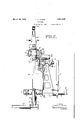
- Fig. i ist p'ianfishbwing .nl detaiiul. trition drive cones, certain ⁇ portions'being brof ken awayV to disclosethe interiorV mechanism.
- the portionsin Fig. .4 which are in section are on the ⁇ plane indieatedby line .el-.4v of Fig.,3.
- Fig. is a sidezelevation F g. 2 isanendelevation ofthe harvester i Fig.k 5 is a crosssection ontheline ,5.-5V
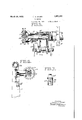
- ⁇ F 7 is a detail of the drive cone actuator.
- Y r In f its ⁇ preterred form, the harvester', attachment ofmy inventioncomprises .an auxandscarryingcrankafrms for engagement with the ground contacting wheelsand includes iliaryaXle lattached" to asstandardharv'ester Y '65 also ,a yvariable spacing means between the crank arms and the standard harvester axle for regulating .the degreeo-i: ⁇ spacing VofV the ground wheels fromv thelharveste'r body. I.
- I preferably attach the device of my invention to a stand-v framework7 aty its forward.v end bearing von a steering wheel 8 andwhich at its rearward vend-carries astandardaxle 9.
- the standard harvester Ifpreferably remove each of the usual ground 'engaging wheels-from the standardI aXle 9 andv substituterforleach of ment of my invention is ⁇ in two" units, ⁇ one on each side ⁇ of the machine, but since these units lare identical I shall describe hut'one of them herein.mV4 f f
- the bracketll .attached nonv-rotatably to the axle ⁇ 9andr'to the frame extends fard-"harves ⁇ ter 6 which ⁇ isprovidedfwithvv a- .l 13. It is. to be understood that thefattachf 85,
- a 'means for selectively locating the fgroimel'en'gaging wheeljwith' respect to the harvester body I ' provide :the adjusting lme'chanisrn v14 previously mentioned.; Fastened to the Vcrank ⁇ arm 22V adjacent-faxle 23 isja pair Yof ears 2o-and4v 2?? ⁇ beiIweenthem carryf ingpivotallya screw'sh'aft 28.
- Thisshaft Y extends'approximately vertically f and is :threaded 'throughout substantially its entire'Y length. En'eonipjassingsfthe screw shaft fis.
- a 'carrier i 29 preferably :of bifure'ated; een- .struction andfprovidredadjaeent itsiowerend with apaiir 1'oftran.ni-ons: 3.1 an'dYBQt-he axis of which visperpendicular to the axis ofthe screw 'shaft fand which 'likewise V:is 'p erpendicularpto the axisl 33 of a yoke 34 thefs'epa.-
- Vscrew shaft 28. :is to permit the lower end of thegserewishaft tefswing finflanareaabout 'the axis vho'faxlef21 and theupperfendtlieref-j. 5- fof to* oseillatefslightly; transversely ef the harvester, 1tofcomfpensatel for any-strains and .Ystressesieluetomisalignmentthereof.
- thrust bearing is1iin-terp'o'se'd between the Iupper farmi l'of 'carrier k29 fand Y:the upper end Vof nat 41.
- Vtlieliinit provided for rotating .the gear kv43 to 'effect preferably I prov-ide power operated imean's.
- Meshingfwith gear 243l is a p'iniion44fmount- "ed "on the upper end of 1a :shaft vL46suitably 'journal-led "in ibearings74'7. V'and '48;mounted in a boss 49 projecting from the carrier-29. -At it'lielmzver end yo'f-fsliaft 4611 provide a friction wheel lwhieh keyed thereto :and
- the friction wheelv is selectively engaged by Y either vone of two friction cones 52 vand' 53' which are fixed on across shaft 54extendi ing with its axis perpendicularto4 the axis-7- ofshaft 4G andcarrying a drive's'proclet 56 at its extremity.
- the shaft 5,4 is mounted in f suchv a fashion thatI it may be axially moved to engage either cone 52er cone 53with the Y K friction wheel 51 in order to impart motionV .in either of twol dilferent directionsy tol the shaft 46.
- o vl referablyV I uti'liiz'ethe: source of r:power ordinarilyavailableon,the harvester for actu- ⁇ ating th'e'- adjustingmechanism' .previously described.”
- JA sprocket chain ffengages the sprocket wheel56 and engagesias wella second sprocket 67.1 idler ⁇ - ⁇ 68KV bears 4against the l chainfand keeps it :properly tautened, '-f'lhe 'sprocket 67isfon' av shaftamounted in bear-fl ings 71 ⁇ and T2-fastened to the bracket 11s.
- either one or fthe other .of Ithefriction wheels is engagedatthe discretion "of the 4voperatin and' through the train* ⁇ of mechanism ath'einut 41 is revolved bypower to raise or loWer the ground engaging Wheels. It is customaryto raise the 'Wheel on vone side of the machine WhileloWering the Wheellon the otherside of the machine to accommodate the entire harvester to an inclination of the field in Which it is Working. ⁇
- both of the ground spacing mechanisms may be operated simultaneously in the same direction.
- a harvester attachment comprising ,aV
- Vcrank arm pivoted to said harvester
- a harvester attachment comprising a crank arm pivoted to said harvester, a ground engaging Wheel connected to said crank arm,
- a harvester attachment comprisingv a standard a'xle on said harvester, a ground engaging Wheel, and load-supporting means carried on said axle for variously positioning said Wheel vertically With respect tor said standard axle.
- a harvester attachment comprising a standard axle on said harvester, an auxiliary axle and said auxiliary axle to effect pivotal movement of said auxiliary axle.
- a harvester attachment comprising a standard axle, a crank arm mounted on said harvester to pivot about an axis parallel to' said standard axle and remote therefrom, an
- auxiliary axleV mounted on said crank arm adjacent said standard'axle, a ground engagn ing Wheel on said auxiliary axle, and extensible loadesupporting .means 'connecting said 1 crank armiand saidstandard axle.
- a harvester attachment comprising a' "crank arm pivotallyiconnectedto said-har-y vester, a ground engaging Wheel carried by saidcrankarm, a standard axle'on said har- ⁇ vester,:r bracket on said standardfaxle, a screw y shaft connected tol'said crank arm, and anut j rotatably mounted onsaid bracketand engagingsaid screWshaft, i w 8.'
- a harvester attachment comprisinga frame, a pairA of axles mounted Von said' frame, a crank arm pivotally mounted on oneof said! axles, a Wheel mounted onV said crank arm, ay
- a harvester attachment comprising az standard axle, a'bracket on said standardaxle,
- a harvester attachment comprising ,a
- a harvester, a vvhreelgand adjusting means for said Wheel comprising a member connected thereto and universally connected to ysaid harvester.
- a harvester, a Wheel,and an adjustable support for said Wheel comprising a ⁇ crank axle on said harvester and a screw shaft universally connected to said harvester.
- Y 16 A harvester, a crank axle Yon said harvester, and adjusting meanstherefor carried only on an axle of the harvester.
- a harvester having an axle, a crank axle on said harvester',A adjusting means forVV j y ⁇ 12o crank axle on said harfV v i .v said crank laxle, 1andV a unitarysupprtfor' onsaid-.har-
- said adjusting means carred. Vester;ax1e. v
Landscapes
- Life Sciences & Earth Sciences (AREA)
- Environmental Sciences (AREA)
- Agricultural Machines (AREA)
Description
March 29, 1932. H THOEN 1,851,410
HARVESTER Filed May 28, 1929 4 SheeS-Sheell'l 1 FlE l ATTORNEYS March 29, 1932. H THOEN 1,851,410
HARVESTER Filed May 28, 1929 4 Sheets-Sheet 2 Flai INVENTOR Y ou/e H. Thea/7;-
A TTORNE YS March 29, 1932.
HARVESTER Filed May 28, 1929 4 Sheets-Sheet 4 1N V EN TOR BY Off/@N /f 7/706/7 A TTORNE YS Patented Mar. 1.932v
; 'i UNITDT-STATES oo., F SAN LEANDRO. .oALironNIa A conronA'rIoN or CALLEQRNIAQL f HARVESTER y Application led May :28, 1929. Serial No. :S6-`,5`5 9.fv
Y My invention relates to `harvesters adapted to be propelled over a field of grainfor cutting land threshing the grain therein. Such harvestersmust beadaptable to all diterent v contours and conditions of terrainyincluding not only level' elds but also rolling country and hills. In Yharvesters non7 constructed it is essential in the harvesting operation that Vthe separating mechanism be kept approxii'n matelylevel despitefthe `character of4 the countryover which .the vehicle is propelled.
To meet this-need harvesters have been constructed :tor operation on hillsides and in rolling `country and'these are usually termed side-hill harvesters; They are' provided with manufacturing scheme` `and they'` are Vdealt l with: in V"commerce as two distinct. types of mechanism. f
It is an object of my invention to. provide an attachment for a standard level land harvester which will permit it to be used as a side-hill machine. i j l Anotherobject of my invention is to simplify the mechanism for adapting a harvester to side-hill work. Y f
Another object of my invention is to Vprorvide a power operated means for adjusting the side-hill harvester to different degrees of ground inclination. i i Y Y 40 A further object of my invention is to provide an improved supporting means for the p side-hilll adjusting mechanism. i 'The foregoing and' other objects' are att-ained inthe embodiment of th-e invention 45. shown in the drawings, in which attachment applied toia'harvester.
attachment (of my invention. Y
Fig. i ist p'ianfishbwing .nl detaiiul. trition drive cones, certain `portions'being brof ken awayV to disclosethe interiorV mechanism. The portionsin Fig. .4 which are in section are on the `plane indieatedby line .el-.4v of Fig.,3.
. PATENT*OFFICE.-
LownLI. H. THOEN, on -srooKTo-N, oALiFonNiA, lAssreiion oA'rEnPiLLAa mationen l;
Fig. is a sidezelevation F g. 2 isanendelevation ofthe harvester i Fig."k 5 is a crosssection ontheline ,5.-5V
of Fig.2.
l Fig. `6-i`s a cross sectionl theline, y
` F 7 is a detail of the drive cone actuator. Y r In f its `preterred form, the harvester', attachment ofmy inventioncomprises .an auxandscarryingcrankafrms for engagement with the ground contacting wheelsand includes iliaryaXle lattached" to asstandardharv'ester Y '65 also ,a yvariable spacing means between the crank arms and the standard harvester axle for regulating .the degreeo-i: `spacing VofV the ground wheels fromv thelharveste'r body. I.
. As disclosed inthe drawings, I preferably attach the device of my invention to a stand-v framework7 aty its forward.v end bearing von a steering wheel 8 andwhich at its rearward vend-carries astandardaxle 9.` In providing the standard harvester with the attachment of'my'invention Ifpreferably remove each of the usual ground 'engaging wheels-from the standardI aXle 9 andv substituterforleach of ment of my invention is `in two" units,` one on each side` of the machine, but since these units lare identical I shall describe hut'one of them herein.mV4 f f The bracketll .attached nonv-rotatably to the axle `9andr'to the frame extends fard-"harves`ter 6 which` isprovidedfwithvv a- .l 13. It is. to be understood that thefattachf 85,
' ILL.
l 2x1' 1,851,410Vv upwardly'to carry power driven 4adjusting lwhich will be hereinafter described. .is secured to the frame 7 a cross member 15 m'echanismrgenerally designated as'14 and There carryingat its extremitiesbosses `18 and 19 between which is mounted al stub or'auxiliary axle 21. Journalled on the axle 21 is acrank arm 22 extending rearwardly of the harvester and at its trailing end carrying an axle shaft 23 for reception 'of a ground wheel 'Y 2,4. The ground engaging `Whoo-124 is (free. to pivot about the axisof auxiliary axle `2l in a l vertical plane to vary the'distance between thevground engaging portion of the wheel 'andthe bodyof harvester 6. In this fashionv 'the inc'lination'of Vthe harvester'bodywith Vrespectto the ground'canbe alteredv to ac-v commodate the vehicle to operation over un'-V -dulatory or hilly country.
. a 'means for selectively locating the fgroimel'en'gaging wheeljwith' respect to the harvester body I 'provide :the adjusting lme'chanisrn v14 previously mentioned.; Fastened to the Vcrank` arm 22V adjacent-faxle 23 isja pair Yof ears 2o-and4v 2?? `beiIweenthem carryf ingpivotallya screw'sh'aft 28. Thisshaft Y extends'approximately vertically f and is :threaded 'throughout substantially its entire'Y length. En'eonipjassingsfthe screw shaft fis.
a 'carrier i 29 preferably :of bifure'ated; een- .struction andfprovidredadjaeent itsiowerend with apaiir 1'oftran.ni-ons: 3.1 an'dYBQt-he axis of which visperpendicular to the axis ofthe screw 'shaft fand which 'likewise V:is 'p erpendicularpto the axisl 33 of a yoke 34 thefs'epa.-
' frate farms-@of 'which 361 fand 37 respectively 1encompasis theitrunniions' for pivotal move- 'in'e'nt withrespect `thereto Vand die shank 38 '4b o'f 'which is-.jonrnallefdi `in ith'e' upper end.
of 'bracket The universal #mounting .for
- Vscrew:shaft 28. :is to permit the lower end of thegserewishaft tefswing finflanareaabout 'the axis vho'faxlef21 and theupperfendtlieref-j. 5- fof to* oseillatefslightly; transversely ef the harvester, 1tofcomfpensatel for any-strains and .Ystressesieluetomisalignmentthereof.
@In Aorderto' Ydispose fthescr'ewshaft .281m
.any selectediaxially translated positionv with Srespect-fto carrier L29v f1. preferablyprowide ia nut -4-21 engaging the threads l.of fthe' screw "shaftiand locatedV between ithe -bifurcatedA portions of .the 'carrier'29..A YExpeflien't-ly, a
thrust bearing is1iin-terp'o'se'd between the Iupper farmi l'of 'carrier k29 fand Y:the upper end Vof nat 41. Formed integrally with Vtlieliinit provided for rotating .the gear kv43 to 'effect preferably I prov-ide power operated imean's.
Meshingfwith gear 243lis a p'iniion44fmount- "ed "on the upper end of 1a :shaft vL46suitably 'journal-led "in ibearings74'7. V'and '48;mounted in a boss 49 projecting from the carrier-29. -At it'lielmzver end yo'f-fsliaft 4611 provide a friction wheel lwhieh keyed thereto :and
,rotates in unison with-the pinion-44.V The friction wheelv is selectively engaged by Y either vone of two friction cones 52 vand' 53' which are fixed on across shaft 54extendi ing with its axis perpendicularto4 the axis-7- ofshaft 4G andcarrying a drive's'proclet 56 at its extremity. The shaft 5,4 is mounted in f suchv a fashion thatI it may be axially moved to engage either cone 52er cone 53with the Y K friction wheel 51 in order to impart motionV .in either of twol dilferent directionsy tol the shaft 46. Surrounding land supporting Jthe 1shaft54 are be'ar1ngs'57.- held against axial movement'on the shaft kand in turn mounted in'a sleeve 58 rotatably coniined ina" collar f "59 bolted 'to carrier 29:vr
v'dle, .the 4sleeve is both rotate'dzrand `translated axially so that either one ortherother oftheVv Y friction cones 52la11d 53Vis-.1noved `into fric.- `tional engagement with thefrfiction 4wheel 51. Since the shaft 54 isxrotated through the j vmedium of sprocket 56, ay correspondingra tation is imparted to rshaft'46 andl :to the .nut 4.1. Depending upenn-whichV ofthe 'Cones v52 or 53 is .in engagement with 'the ffricti'oi'i thescrew Yshaftjf28 'to pivot `the crank ar1ne22 Connected;v to L the' sleeve 58' iisa-v handle Y ywheel, the-nut willlcause axial movement of if Y either 4upward'lyff'or downwardly, .thereby varying j-the relationship between thel ground:
lengaging wheel and. the 'body of the ,han
vester.
o vl referablyV I uti'liiz'ethe: source of r:power ordinarilyavailableon,the harvester for actu- `ating th'e'- adjustingmechanism' .previously described." JA sprocket :chain ffengages the sprocket wheel56 and engagesias wella second sprocket 67.1 idler`-`68KV bears 4against the l chainfand keeps it :properly tautened, '-f'lhe 'sprocket 67isfon' av shaftamounted in bear-fl ings 71` and T2-fastened to the bracket 11s.
.A sprocket vzm'esheswith av chain;74 lconnected with -theV rharvestirng Vmechanism `so that the sprockets are driven while .the harvester mechanism is being rotated.
`In anyV :given: adjusted position .of 'theV ground engaging wheels 'withl respect to the harvester body, bothfrictioncone-52 Yand 'friction cone 53 are out of engagement vwith the friction* wheel 51 and the ypitch of the thread on the screw/shaft 28 is such that *nov movement betweenvthe nut 41and thefscrew shaft takes place and the' ground `engaging wheels Vremain inv their adjusted'y position.
no Y
Upon movement rof-'the leverv 64,1'h'owever,
either one or fthe other .of Ithefriction wheels is engagedatthe discretion "of the 4voperatin and' through the train*` of mechanism ath'einut 41 is revolved bypower to raise or loWer the ground engaging Wheels. It is customaryto raise the 'Wheel on vone side of the machine WhileloWering the Wheellon the otherside of the machine to accommodate the entire harvester to an inclination of the field in Which it is Working.` However, in order to gain height to clear obstructions or to lower the harvester body both of the ground spacing mechanisms may be operated simultaneously in the same direction.
It Will be appreciated that I have provided'v i a harvester attachment Which can, be appli-ed to a standard harvester With substantially no change thereof and Which renders the standard harvester variable for use in hilly and undulatory country. Furthermore, the power required to effect the adjustment of the harvester to its peculiarconditions is.
derived from the engine and ispcompletely under control of the harvester operator.`
It is to be understood that I do not limit myself to the form of the harvester attachment shoWn and described herein, as the in# vention, as set forth in the following claims may be vembodied in a plurality of forms.
I' claim: Y
1. A harvester attachment comprising ,aV
Vcrank arm pivoted to said harvester, a
ground engaging Wheel mounted on said crank arm, a standard axle on said harvester,
Y and positioning means connecting said standard axle and said crank arm. f- Y 2. A harvester attachment comprising a crank arm pivoted to said harvester, a ground engaging Wheel connected to said crank arm,
a standard axle on said harvester, and loadsupporting means for variously positioning said Wheel With respect to said standard axle.
3. A harvester attachment comprisingv a standard a'xle on said harvester, a ground engaging Wheel, and load-supporting means carried on said axle for variously positioning said Wheel vertically With respect tor said standard axle. j Y
4. A harvester attachment comprising a standard axle on said harvester, an auxiliary axle and said auxiliary axle to effect pivotal movement of said auxiliary axle.
6. A harvester attachment comprising a standard axle, a crank arm mounted on said harvester to pivot about an axis parallel to' said standard axle and remote therefrom, an
auxiliary axleV mounted on said crank arm adjacent said standard'axle, a ground engagn ing Wheel on said auxiliary axle, and extensible loadesupporting .means 'connecting said 1 crank armiand saidstandard axle. v
1 7. A harvester attachment comprising a' "crank arm pivotallyiconnectedto said-har-y vester, a ground engaging Wheel carried by saidcrankarm, a standard axle'on said har-` vester,:r bracket on said standardfaxle, a screw y shaft connected tol'said crank arm, and anut j rotatably mounted onsaid bracketand engagingsaid screWshaft, i w 8.' A harvester attachment comprisinga frame, a pairA of axles mounted Von said' frame, a crank arm pivotally mounted on oneof said! axles, a Wheel mounted onV said crank arm, ay
bracket mounted on the other of said axles, and means for variably positioning said crank arm With respect to said bracket 1 9. A harvester attachment comprising az standard axle, a'bracket on said standardaxle,
so i.
ayoke pivoted inl said bracket, a mitoyen-185.
'strained to rotation on said yoke, an auxiliary axle, a crank armpivoted on saidauxiliary-1 axle, a ground engaging Wheel on said crank arm, and ascrevv shaft connected to said crank arm and engaging said nut. v
V10. A harvester attachment comprising ,a
l frame, a standard axle secured to said frame`,',. -a bracket aiiixed to said axle, a yoke mounted on said bracket to pivot about an axis,` -a carrier mounted on said yoketo pivot about a second axis parallel toA said axis, a nut con-` strained to rotation in said carrier, an aux- Y iliary axle secured to said frame, a crank Varm pivotally mounted on said auxiliary axle,a ground engaging Wheel, rotatably mounted on said crankarm, and a screw shaft pivoted to said crank arm and engaging said j nut.
11. A harvester, a vvhreelgand adjusting means for said Wheel comprising a member connected thereto and universally connected to ysaid harvester.
12. A harvester, a Wheel, and anadjustable support for said Wheelcomprising `a crank axle onsaidharvester and amember universally connected to said harvester. Y
iio
1". A harvester, a Wheel,and an adjustable support for said Wheel comprisinga` crank axle on said harvester and a screw shaft universally connected to said harvester.
15. A harvester, a vester, adjusting means therefor, a unitary support for said adjusting means, and Va -universal connection between saidV adjusting means 'and said support. Y 16. A harvester, a crank axle Yon said harvester, and adjusting meanstherefor carried only on an axle of the harvester. j
17.` A harvester having an axle, a crank axle on said harvester',A adjusting means forVV j y `12o crank axle on said harfV v i .v said crank laxle, 1andV a unitarysupprtfor' onsaid-.har-
said adjusting means. carred. Vester;ax1e. v
1'8. "A harvester-having fanax1e,a crank v`a-Xle on said; harvester, adj ustingmeans for saidfcranl; axle, aiunitarysupport' for'said z 4adjusting meansrcarriednon said harvesterVv axle and a universal Connection lbetween*the vcrank axle and said harvesteraxle. s
In testimony whereofl have hereunto set .myhand. s f l LOWELL H. THOEN.
A In)
Priority Applications (1)
| Application Number | Priority Date | Filing Date | Title |
|---|---|---|---|
| US366559A US1851410A (en) | 1929-05-28 | 1929-05-28 | Harvester |
Applications Claiming Priority (1)
| Application Number | Priority Date | Filing Date | Title |
|---|---|---|---|
| US366559A US1851410A (en) | 1929-05-28 | 1929-05-28 | Harvester |
Publications (1)
| Publication Number | Publication Date |
|---|---|
| US1851410A true US1851410A (en) | 1932-03-29 |
Family
ID=23443535
Family Applications (1)
| Application Number | Title | Priority Date | Filing Date |
|---|---|---|---|
| US366559A Expired - Lifetime US1851410A (en) | 1929-05-28 | 1929-05-28 | Harvester |
Country Status (1)
| Country | Link |
|---|---|
| US (1) | US1851410A (en) |
Cited By (1)
| Publication number | Priority date | Publication date | Assignee | Title |
|---|---|---|---|---|
| US3186548A (en) * | 1962-04-30 | 1965-06-01 | Clark E Stroburg | Leveling device for the chaffer and sieve on a combine |
-
1929
- 1929-05-28 US US366559A patent/US1851410A/en not_active Expired - Lifetime
Cited By (1)
| Publication number | Priority date | Publication date | Assignee | Title |
|---|---|---|---|---|
| US3186548A (en) * | 1962-04-30 | 1965-06-01 | Clark E Stroburg | Leveling device for the chaffer and sieve on a combine |
Similar Documents
| Publication | Publication Date | Title |
|---|---|---|
| US2669826A (en) | Lawn mower of the rotating sickle type | |
| US4324091A (en) | Vehicular forage harvester | |
| US20140373496A1 (en) | Harvesting machine comprising a servo-control means for the lifting height of a work tool | |
| BR102013030240A2 (en) | CONDITIONER, AND METHOD TO PREVENT HARVESTING | |
| US11197404B2 (en) | Sand bunker rake and infield groomer apparatus | |
| US3251631A (en) | Discharge spout control | |
| US3721076A (en) | Adjustable mower suspension system | |
| US2764864A (en) | Mower elevating means | |
| US2652679A (en) | Windrow turning apparatus | |
| US2476394A (en) | Mowing machine | |
| US3589109A (en) | Control system for fluid motor | |
| US2656668A (en) | Header mount for sidehill harvesters | |
| US1851410A (en) | Harvester | |
| US6308504B1 (en) | Device for treating cut fodder and mower employing such a treatment device | |
| US2501424A (en) | Push-type full vision swather | |
| US2701940A (en) | Adjustment mechanism for agricultural flailing machines | |
| US1557902A (en) | Lawn mower | |
| US2674837A (en) | Power-operated lawn mower | |
| US3672140A (en) | Cranberry harvesting apparatus | |
| US3203160A (en) | Lawn mowers | |
| US5548949A (en) | Hay making machine with carrying wheels | |
| US2833102A (en) | Variable pitch mower | |
| US2958175A (en) | Self-propelled corn topping device | |
| US1493223A (en) | Lawn mower | |
| US4538406A (en) | Mechanical berry harvester having row-width-adjustable beater |