US1851403A - Lathe chuck - Google Patents
Lathe chuck Download PDFInfo
- Publication number
- US1851403A US1851403A US342832A US34283229A US1851403A US 1851403 A US1851403 A US 1851403A US 342832 A US342832 A US 342832A US 34283229 A US34283229 A US 34283229A US 1851403 A US1851403 A US 1851403A
- Authority
- US
- United States
- Prior art keywords
- chuck
- work
- lathe
- engagement
- adapter
- Prior art date
- Legal status (The legal status is an assumption and is not a legal conclusion. Google has not performed a legal analysis and makes no representation as to the accuracy of the status listed.)
- Expired - Lifetime
Links
- 239000003638 chemical reducing agent Substances 0.000 description 4
- 230000002093 peripheral effect Effects 0.000 description 4
- 230000015572 biosynthetic process Effects 0.000 description 3
- 238000005755 formation reaction Methods 0.000 description 3
- 230000000717 retained effect Effects 0.000 description 3
- 238000010276 construction Methods 0.000 description 2
- 238000003780 insertion Methods 0.000 description 2
- 230000037431 insertion Effects 0.000 description 2
- 239000002184 metal Substances 0.000 description 2
- 230000004048 modification Effects 0.000 description 2
- 238000012986 modification Methods 0.000 description 2
- 230000002452 interceptive effect Effects 0.000 description 1
- 230000003137 locomotive effect Effects 0.000 description 1
- 238000003754 machining Methods 0.000 description 1
- 239000000463 material Substances 0.000 description 1
- 238000002360 preparation method Methods 0.000 description 1
- CEWNUSPMSSUSJA-AATRIKPKSA-N ustin Chemical compound O1C(=O)C2=C(C)C(Cl)=C(O)C(Cl)=C2OC2=C(Cl)C(C(/C)=C/C)=C(O)C(C)=C21 CEWNUSPMSSUSJA-AATRIKPKSA-N 0.000 description 1
Images
Classifications
-
- B—PERFORMING OPERATIONS; TRANSPORTING
- B23—MACHINE TOOLS; METAL-WORKING NOT OTHERWISE PROVIDED FOR
- B23B—TURNING; BORING
- B23B31/00—Chucks; Expansion mandrels; Adaptations thereof for remote control
- B23B31/02—Chucks
- B23B31/10—Chucks characterised by the retaining or gripping devices or their immediate operating means
- B23B31/12—Chucks with simultaneously-acting jaws, whether or not also individually adjustable
- B23B31/20—Longitudinally-split sleeves, e.g. collet chucks
- B23B31/201—Characterized by features relating primarily to remote control of the gripping means
- B23B31/202—Details of the jaws
-
- Y—GENERAL TAGGING OF NEW TECHNOLOGICAL DEVELOPMENTS; GENERAL TAGGING OF CROSS-SECTIONAL TECHNOLOGIES SPANNING OVER SEVERAL SECTIONS OF THE IPC; TECHNICAL SUBJECTS COVERED BY FORMER USPC CROSS-REFERENCE ART COLLECTIONS [XRACs] AND DIGESTS
- Y10—TECHNICAL SUBJECTS COVERED BY FORMER USPC
- Y10T—TECHNICAL SUBJECTS COVERED BY FORMER US CLASSIFICATION
- Y10T279/00—Chucks or sockets
- Y10T279/17—Socket type
- Y10T279/17411—Spring biased jaws
- Y10T279/17487—Moving-cam actuator
- Y10T279/17504—Threaded cam sleeve
- Y10T279/17512—Loose jaws
Definitions
- This invention relates to improvements in lathe chucks, having for an object to provide a chuck of the character mentioned, s0. con
- Another and equally important object of the invention may be stated to provide a lathe chuck that will be especially advantageous for use in securing the so-called pop valve of steam let-off safety appliances, now widely used in connection with the steam boilers of locomotives during a grinding or reconditioning of the same, allowing the valves to be accurately centered upon the lathe and to be securely retained Without the forming of chuck j aw "markings, thereon which, necessitate a deeper grinding ofthe .valves to efiect contact or seat portions thereupon, and the resultant forming of pressures therein, consequently, interfering withproper operation of such valves.
- Yet another object of the invention may 7 be stated to reside in the provision of a chuck having reducer or adapter means capable of ready insertion therein, whereby valves of smaller size may beeffectually engaged and retained therein.
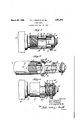
- Figure 1 is a longitudinal section through the improved chuck showing the engagement of a portion of a pop valve therein together with the usage of a reducer or adapter device; o
- Figure 2 is a disassembled detail per manner in which a reducer or adapter device is adapted to be engaged therein, and the manner in which a pop valve is engaged, and v Figure 73 is aside elevation'of a slightly modified form of the improved chuck. 1 Having, more particular 7 reference to, the drawings, in connection with which like Characters of reference will'designate corre-.
- the improved chuck may be stated to comprise a cross sectionally circular tubular or sleeve-like metal body indicated in its entirety herein by the numeral 1,-sa id body being formed with an intermediately thickened portion 2, fwhile an internally screw threaded socket is formed upon the lathe receiving end thereof in order that effectual connection as between a chuck andthe screw, threaded portion 3 of the spindle of a lathe fl may be engaged or turned thereinto, as is clearly shown in the Figure 1; i
- the opposite or, remaining end of the chuck body 1 is formed with across sectionally circular and tapered work piece receiving I means 6 having the outer peripheral surface thereof screw threaded as at 7 and being formed with-a plurality of relativelyspaced longitudinally disposed slots 8 whereby to divide the work piece receiving means of the chuck into a plurality of segmental arms capable of being flexed with respect to the chuck body 1, for a purpose that will be presently described.
- the work piece receiving means 6 may be fiexedand brought into binding and retaining engagement with a pop valve engaged therein,
- spanner nut 10 forming the usual spanner wrench'receiving slots or notches 11 in its outer peripheral surface whereby to permit ofefl'ectual that the segmental chuck arms of,
- the diameter of the adapter 13 issuch that it wjill be assuredof snug longitudinal and. slidable engagement in the workfreceivin means '6 of the, improved .chuck,in the fashion: as is shown inthe Fig- 7 1,T the segmental, gripipingfand securing 7 portions thereof being'fac di'outwardly, as
- a rid"2 while an innerperipherally, disposed shoulder or lip 15 is formed upon' the segment piQrtiolnsg'of the ,adapted and serves to permit of the snug engagement 7' of :the t peripheral or barrel-like J o eo rs i adapte s '13, 6r difiernt' inside 1iametersima -'b provided the'chuck, such ras, conditi0nsfor preference may dictate,
- This nut 10 instead of being formed with the spanner wrench receiving notches 11, is preferably of polygonal or multi-sidedoute'r formation
- Adapter or reducer devices ma ,”of-'ei1ree, be usedin connection with the spring o'r'fle'x- 5 or character of chuck 'shown 'inth'e Figure 3, in the same fashion are the adapter devices 13 used infconnection with the chucks'ho'wn in thej Figures 1 and 2.
- r 'TIn operation of our" improved chuck and referring in particular, to the form illustrat ed in the Figuresl and 2, the chuck isfirst-slet up with respect jto'the lathespindle 3 by tun ing I the j internally screw 'thr"e aded "socket portion ofthe'fsame onto said spindle.
- segmental parts of the means 6 to flex-the same into binding and securing engagement with the adjacent portions of said valve.
- the species of invention disclosed in the Figure 3 is operated in a manner corresponding to the operation described in connection with that form or species of the invention illustrated in the Figures 1 and 2, with the exception, that instead of using a spanner wrench in connection with the thickened intermediate body portion of the chuck and with the adjusting and locking nut, a wrench of the ordinary straight jaw type is employed, the same being adjusted and engaged with the multi-sided formations or faces of the adjusting and locking nut 10 and the intermediate portion 12.
- a chuck comprising a cylindrical body having an intermediately thickened portion formed therewith for dividing the same into an attaching end and a work holding end, said work holding end having a plurality of longitudinally disposed slots therein forming a plurality of gripping arms, the outer periphery of said work holding end being tapered and having screw threads thereon, an adapter receivable in the arms of said work holding end, said adapter having a plurality of slots therein forming gripping arms corresponding with the gripping arms of said work holding end, and a nut engageable with the tapered threaded periphery of the work holding end of the chuck whereby the arms of the latter may be forced into gripping engagement with said adapter and. the pressure so exerted upon the arms of the work holding end of the chuck being trans mitted to the arms of the adapter for causing the latter to grip the work held thereby.
- A. chuck comprising a body having a a Work holding end, said work holding end having a recess formed therewith and extending throughout its length, said work.
- a chuck comprising a cylindrical body having an internal intermediately positioned thickened portion, internal threads formed with one end of said body for receiving a lathe spindle, said intermediately thickened portion of the body forming a shoulder adjacent the inner extremityv of the internal lathe spindle receiving threads, the peripheral portion of the opposed end of said body being tapered and threaded forming a work receiving end, said work receiving end having a recess therein extending throughout its entire length, said work receiving end of the body having a plurality of longitudinally disposed slots therein opening to the outer extremity of the work end and being of a length less than that of said work receiving end to form a plurality of gripping arms, a collet receivable in said recess of the work receiving end and having a plurality oflongitudinally disposed slots therein opening at one extremity of the collet to provide a plurality of work holding and gripping arms, and a nut engageable with the tapered threaded periphery of said work gripping
Landscapes
- Engineering & Computer Science (AREA)
- Mechanical Engineering (AREA)
- Gripping On Spindles (AREA)
Description
March 29, 1932. J PRESTON ET AL 1,851,403
LATHE crwcx Original Filed Feb. 26, 1929 12 v. .I z I Jmnmtot: I E.J.Presl'on v v 4 I W C. Fletcher A .W. Reynolds J1:
1 EARL J.
set out several Patented Mar. 29, 1932 UNITED 'S'TATES IRESTON, WILLIAM G. FLETCHER, AND ALBERT W. REYNOLDS, JR., OF PRINCE-- TON, WEST VIRGINIA, SAID FLETCHER ASSIGNOR TO SAID PRESTON v PATENT OFFICE Y Y LATHE CHUCK,
Application filed February 2 6, Serial 342,832, Renewed. February 1 3, 1932. v
This invention relates to improvements in lathe chucks, having for an object to provide a chuck of the character mentioned, s0. con
structed that the same will function to re-- ceive and secure a piece to be machined in properly centered position on an equipped lathe and furthermore, will efiect a material saving of time and labor in set-up preparations as when a piece is secured in working position through the usage of those types of multiple jaw chucks, now prevalent in this art.
Another and equally important object of the invention may be stated to provide a lathe chuck that will be especially advantageous for use in securing the so-called pop valve of steam let-off safety appliances, now widely used in connection with the steam boilers of locomotives during a grinding or reconditioning of the same, allowing the valves to be accurately centered upon the lathe and to be securely retained Without the forming of chuck j aw "markings, thereon which, necessitate a deeper grinding ofthe .valves to efiect contact or seat portions thereupon, and the resultant forming of pressures therein, consequently, interfering withproper operation of such valves.
Yet another object of the invention may 7 be stated to reside in the provision of a chuck having reducer or adapter means capable of ready insertion therein, whereby valves of smaller size may beeffectually engaged and retained therein. a
Other object-sfof the invention will be in part obvious and part pointed out here-' inafter.
In order that the invention and its mode of operation may be readily understood by persons skilled in the art, wehavein the accomanying illustrative drawings, and inthe detailed following description based thereon, possible embodiments, of the same. v
In these drawings t a Figure 1 is a longitudinal section through the improved chuck showing the engagement of a portion of a pop valve therein together with the usage of a reducer or adapter device; o
Figure 2 is a disassembled detail per manner in which a reducer or adapter device is adapted to be engaged therein, and the manner in which a pop valve is engaged, and v Figure 73 is aside elevation'of a slightly modified form of the improved chuck. 1 Having, more particular 7 reference to, the drawings, in connection with which like Characters of reference will'designate corre-. sponding parts throughout, the improved chuck may be stated to comprise a cross sectionally circular tubular or sleeve-like metal body indicated in its entirety herein by the numeral 1,-sa id body being formed with an intermediately thickened portion 2, fwhile an internally screw threaded socket is formed upon the lathe receiving end thereof in order that effectual connection as between a chuck andthe screw, threaded portion 3 of the spindle of a lathe fl may be engaged or turned thereinto, as is clearly shown in the Figure 1; i
engagement of the screw threaded lathe spindle in the same.
The opposite or, remaining end of the chuck body 1 is formed with across sectionally circular and tapered work piece receiving I means 6 having the outer peripheral surface thereof screw threaded as at 7 and being formed with-a plurality of relativelyspaced longitudinally disposed slots 8 whereby to divide the work piece receiving means of the chuck into a plurality of segmental arms capable of being flexed with respect to the chuck body 1, for a purpose that will be presently described.
In order the work piece receiving means 6 may be fiexedand brought into binding and retaining engagement with a pop valve engaged therein,
somewhat after the fashion ofithe valve indicated herein by thenumeral 9, we provide an adjusting and locking. spanner nut 10, forming the usual spanner wrench'receiving slots or notches 11 in its outer peripheral surface whereby to permit ofefl'ectual that the segmental chuck arms of,
engagement of a Wrench therewith and the rotating of such spanner nut to operative or inoperative positions, as may be required I during the usage of the improved device.
To facilitate a quick and convenient engagement of 'the internally screw threaded socket portion of the chuck body 1 with'the screw threaded lathe spindle 3, we mayand preferablyLfOrm spanneriwren h .reQQiYing pockets or recesses 7 12 in the outer'gperipheral 7 portion of the thickened intermediate p0rtion 2 of said chuck body 1, arranging these sectionally, circular sleeve, jor tubular-like spring metal' e'lements,onefof which is: shown herei'n an d indic ated'infits entiretyby the V numeral "13 saidjadapter being formed with mumm 4 of, longitudinally disposed equispaced slots :14 opening onto one m'arginal portion offthe adapter and hence, providing such vadapterwith a. plurality of flexible or spring segmental gripping or work piece receiving ar'ms. The diameter of the adapter 13 issuch that it wjill be assuredof snug longitudinal and. slidable engagement in the workfreceivin means '6 of the, improved .chuck,in the fashion: as is shown inthe Fig- 7 1,T the segmental, gripipingfand securing 7 portions thereof being'fac di'outwardly, as
.ro e o e hu kvbo y yvi'th; chuck arms lor "work piece "receiving Qineans' 6, externally screw threaded asiat' 7 llandlformedwith ,a plurality'iof relatively vspacedfslofts'. 8" whereby to give flexibility to 1 portion lof the' popvalve Q'the'rein;
shown in the Figures l ,a rid"2,"while an innerperipherally, disposed shoulder or lip 15 is formed upon' the segment piQrtiolnsg'of the ,adapted and serves to permit of the snug engagement 7' of :the t peripheral or barrel-like J o eo rs i adapte s '13, 6r difiernt' inside 1iametersima -'b provided the'chuck, such ras, conditi0nsfor preference may dictate,
Ingthe'klfigure 3, wefhaveshown: a slightly modified form of the} improved chuck, wherein the. same comprises ametal body portion 1", siinilar in construction and formation to theIbody'. l ofthefirst mentioned embodiment of the invention, whereby a working connection may be established asbetween it aiid the .spindle'3 of allatheif theoppo'site end or being formed the ivtloji k' piece receiving means" 6 'so 7 that when the adjusting and .lockingnut ltl is i over the tapered outer-peripheral; and screw threaded surfacethere'of, said means 6 is formed with a inuIti-sided or "nut forma ible work jiece'receivin meansib of'the't 'e lv .v a: v yP This nut 10, instead of being formed with the spanner wrench receiving notches 11, is preferably of polygonal or multi-sidedoute'r formation, hence, permitting it to be'efi'etually engaged by a Wrench or other suitable tool. ec-the at in ediate-p o of he y l 5 tion 12, instead of fih'es' sm'rir wrench receiving'pockets or recesses 12, as describedin connection withthe preceding embodiment of the invention; permitting of the engaging of a wrench with the chuck body and the turning of the same engagement "with the screw threaded portion of the lathe spindl'eb.
Adapter or reducer devices, ma ,"of-'ei1ree, be usedin connection with the spring o'r'fle'x- 5 or character of chuck 'shown 'inth'e Figure 3, in the same fashion are the adapter devices 13 used infconnection with the chucks'ho'wn in thejFigures 1 and 2. r 'TIn operation of our" improved chuck "and referring in particular, to the form illustrat ed in the Figuresl and 2, the chuck isfirst-slet up with respect jto'the lathespindle 3 by tun ing I the j internally screw 'thr"e aded "socket portion ofthe'fsame onto said spindle. Kt this time, a pop valve to be machined is 'sn ugly engaged j'within i the work piece receivin g means 6 of the 'chuck'and thereupon, thea'dj ustin'g locking nut 10 turnejdoutwardlyalonfg the tapered screw'thi ea'ded portions'Z of said work piece receiving fmeans 6, causing the segmental- 'o'rtito'ris thereof tobe flexed inwardly" intda undi frg and seeming engagement with the adjacent or received portions of'sajidfpio p valve 9' and hencef i'mmovably securing the 'sanie in position for machining within; the huck, *Inthisco'n nflction, it will be noted'tliatbe'c-ause o fl-the l ty Q Y s'ql f fi g g ment of "the chu k w thithe pop valve 9j-'said"valve,iwith its 'insertion'in'the jiiieaiis ti iwill beeffectually centered for the subsequent operationand furthermore, it"w'ill 'be'f'se cure in an vimmovable. position vwithouti'the forming hereinbefore stated, require a deepengrindingof contact or seat, portions thereupon.
vIn event that; a smaller pop valve is to be secured the imprqved chuck, an d p f. pre f insid d mn h s s lected and is 'snugly engaged, in the flexible work-piece receiving means 6 the manner as is shown in the Figure}, H whereupon the pop valve to-bemachined, is
engaged within the adapter-or reducerdevice indicated by the numeral" 13 and the; adjust "i'ngo r locking-nut 1Q is 'then turned dutward- 'ly upon the screw threaded portions 7*ofthe E,
segmental parts of the means 6 to flex-the same into binding and securing engagement with the adjacent portions of said valve.
The species of invention disclosed in the Figure 3, is operated in a manner corresponding to the operation described in connection with that form or species of the invention illustrated in the Figures 1 and 2, with the exception, that instead of using a spanner wrench in connection with the thickened intermediate body portion of the chuck and with the adjusting and locking nut, a wrench of the ordinary straight jaw type is employed, the same being adjusted and engaged with the multi-sided formations or faces of the adjusting and locking nut 10 and the intermediate portion 12.
Manifestly, the construction shown is capable of considerable modification, and such modification as is within the scope of our claims we consider within the spirit of our invention.
We claim 1. A chuck comprising a cylindrical body having an intermediately thickened portion formed therewith for dividing the same into an attaching end and a work holding end, said work holding end having a plurality of longitudinally disposed slots therein forming a plurality of gripping arms, the outer periphery of said work holding end being tapered and having screw threads thereon, an adapter receivable in the arms of said work holding end, said adapter having a plurality of slots therein forming gripping arms corresponding with the gripping arms of said work holding end, and a nut engageable with the tapered threaded periphery of the work holding end of the chuck whereby the arms of the latter may be forced into gripping engagement with said adapter and. the pressure so exerted upon the arms of the work holding end of the chuck being trans mitted to the arms of the adapter for causing the latter to grip the work held thereby.
2. A. chuck comprising a body having a a Work holding end, said work holding end having a recess formed therewith and extending throughout its length, said work.
holding end having a plurality of slots formed therein, each being of a length less than that of the recess formed therewith, a collet receivable in said recess and having a plurality of slots formed therein of a length less than that of the collet and equal to the length of the slots within said work holding end of the chuck, the outer periphery of said work holding end of the chuck being tapered and threaded, a nut engageable with said threaded tapered periphery of the work holding end of the chuck for causing a gripping engagement to be effected between the chuck and the work receivable in said collet.
3. A chuck comprising a cylindrical body having an internal intermediately positioned thickened portion, internal threads formed with one end of said body for receiving a lathe spindle, said intermediately thickened portion of the body forming a shoulder adjacent the inner extremityv of the internal lathe spindle receiving threads, the peripheral portion of the opposed end of said body being tapered and threaded forming a work receiving end, said work receiving end having a recess therein extending throughout its entire length, said work receiving end of the body having a plurality of longitudinally disposed slots therein opening to the outer extremity of the work end and being of a length less than that of said work receiving end to form a plurality of gripping arms, a collet receivable in said recess of the work receiving end and having a plurality oflongitudinally disposed slots therein opening at one extremity of the collet to provide a plurality of work holding and gripping arms, and a nut engageable with the tapered threaded periphery of said work gripping end of the body, whereby the said collet may be held into gripping engagement with the work receiving end of the body and the work receivable by said collet retained in gripping engagement therewith.
In witness whereof we have hereunto set our hands.
' EARL J. PRESTON.
ALBERT W. REYNOLDS, JR. WILLIAM O. FLlilTCI-IER.
Priority Applications (1)
| Application Number | Priority Date | Filing Date | Title |
|---|---|---|---|
| US342832A US1851403A (en) | 1929-02-26 | 1929-02-26 | Lathe chuck |
Applications Claiming Priority (1)
| Application Number | Priority Date | Filing Date | Title |
|---|---|---|---|
| US342832A US1851403A (en) | 1929-02-26 | 1929-02-26 | Lathe chuck |
Publications (1)
| Publication Number | Publication Date |
|---|---|
| US1851403A true US1851403A (en) | 1932-03-29 |
Family
ID=23343456
Family Applications (1)
| Application Number | Title | Priority Date | Filing Date |
|---|---|---|---|
| US342832A Expired - Lifetime US1851403A (en) | 1929-02-26 | 1929-02-26 | Lathe chuck |
Country Status (1)
| Country | Link |
|---|---|
| US (1) | US1851403A (en) |
Cited By (3)
| Publication number | Priority date | Publication date | Assignee | Title |
|---|---|---|---|---|
| US2994539A (en) * | 1958-12-02 | 1961-08-01 | Heinrich Tools Inc | Collet assembly with replaceable soft jaw |
| CN103264292A (en) * | 2013-05-29 | 2013-08-28 | 苏州创丰精密五金有限公司 | Clamping sleeve used for meter lathe |
| US11148209B2 (en) | 2018-09-17 | 2021-10-19 | Black & Decker Inc. | Power tool chuck |
-
1929
- 1929-02-26 US US342832A patent/US1851403A/en not_active Expired - Lifetime
Cited By (4)
| Publication number | Priority date | Publication date | Assignee | Title |
|---|---|---|---|---|
| US2994539A (en) * | 1958-12-02 | 1961-08-01 | Heinrich Tools Inc | Collet assembly with replaceable soft jaw |
| CN103264292A (en) * | 2013-05-29 | 2013-08-28 | 苏州创丰精密五金有限公司 | Clamping sleeve used for meter lathe |
| US11148209B2 (en) | 2018-09-17 | 2021-10-19 | Black & Decker Inc. | Power tool chuck |
| US12290864B2 (en) | 2018-09-17 | 2025-05-06 | Black & Decker Inc. | Power tool chuck |
Similar Documents
| Publication | Publication Date | Title |
|---|---|---|
| US2715028A (en) | Socketed wrench holder | |
| US1677473A (en) | Socket wrench and screw driver | |
| US2050005A (en) | Bearing puller | |
| US3115798A (en) | Lathe spindle and collet stops | |
| US1851403A (en) | Lathe chuck | |
| US2297648A (en) | Mandrel | |
| US2351232A (en) | Stud setting and removing tool | |
| US2869237A (en) | Trammel bar compass | |
| US2220654A (en) | Chuck | |
| US2012280A (en) | Chuck mechanism | |
| US2654611A (en) | Adjustable spring jaw chuck | |
| US2678826A (en) | Chuck for shankless drills or reamers | |
| US1526328A (en) | Chuck | |
| US851137A (en) | Pipe-nipple holder. | |
| US1934910A (en) | Collet means | |
| US2228863A (en) | Feeding device | |
| DE342566C (en) | ||
| US2408503A (en) | Pin clutch arbor | |
| US1159248A (en) | Chuck. | |
| US1364361A (en) | Drill-chuck | |
| US2714515A (en) | Extension chuck for twist drills | |
| US2170867A (en) | Pencil | |
| US2786687A (en) | Feed chucks | |
| US965970A (en) | Tap-wrench. | |
| US3056191A (en) | Gripping and pulling implement |