US1851402A - Cigar lighter - Google Patents
Cigar lighter Download PDFInfo
- Publication number
- US1851402A US1851402A US367369A US36736929A US1851402A US 1851402 A US1851402 A US 1851402A US 367369 A US367369 A US 367369A US 36736929 A US36736929 A US 36736929A US 1851402 A US1851402 A US 1851402A
- Authority
- US
- United States
- Prior art keywords
- shield
- backing
- blade
- cigar lighter
- screw shell
- Prior art date
- Legal status (The legal status is an assumption and is not a legal conclusion. Google has not performed a legal analysis and makes no representation as to the accuracy of the status listed.)
- Expired - Lifetime
Links
- 235000019506 cigar Nutrition 0.000 title description 9
- 238000009413 insulation Methods 0.000 description 6
- 239000011810 insulating material Substances 0.000 description 4
- 238000010276 construction Methods 0.000 description 3
- 238000010438 heat treatment Methods 0.000 description 2
- 239000002184 metal Substances 0.000 description 2
- 229920001342 Bakelite® Polymers 0.000 description 1
- 239000004637 bakelite Substances 0.000 description 1
- 230000015572 biosynthetic process Effects 0.000 description 1
- BFPSDSIWYFKGBC-UHFFFAOYSA-N chlorotrianisene Chemical compound C1=CC(OC)=CC=C1C(Cl)=C(C=1C=CC(OC)=CC=1)C1=CC=C(OC)C=C1 BFPSDSIWYFKGBC-UHFFFAOYSA-N 0.000 description 1
- 235000019504 cigarettes Nutrition 0.000 description 1
- 239000004020 conductor Substances 0.000 description 1
- 230000002708 enhancing effect Effects 0.000 description 1
- 238000005755 formation reaction Methods 0.000 description 1
- 238000004519 manufacturing process Methods 0.000 description 1
- 239000000463 material Substances 0.000 description 1
- 229910052573 porcelain Inorganic materials 0.000 description 1
- 238000009423 ventilation Methods 0.000 description 1
Images
Classifications
-
- F—MECHANICAL ENGINEERING; LIGHTING; HEATING; WEAPONS; BLASTING
- F23—COMBUSTION APPARATUS; COMBUSTION PROCESSES
- F23Q—IGNITION; EXTINGUISHING-DEVICES
- F23Q7/00—Incandescent ignition; Igniters using electrically-produced heat, e.g. lighters for cigarettes; Electrically-heated glowing plugs
Definitions
- This invention relates to cigar or cigarette lighters ot the electrical type and has particular reference to a device of the type disclosed in my prior application No. 265,151,
- a general object of the invention is to provide a device of the class described which is light in weight, strong, durable, of attractive appearance, and which is thoroughly reliable and eilicient in use, thereby enhancing the device from a practical and manufacturing standpoint.
- Another object of the invention is to provide a device embodying a novel casingor standard which may be made of moldable insulating material and which possesses novel structural features and characteristics which vfacilitate assembly and also contribute materially to the general usefulness and appearance of the device.
- a further object of the invention is to profide a novel receptacle for receiving the heating unit, the same including a metallic guard surmounting the base or standard and having insulation and ventilation means which provide tor the safety oi the d evice in use and also protect the user against unduly heated exterior surfaces.
- the saine consists in the novel construction, combination and arrangement of parts hereinafter more fully described, illustrated and claimed.
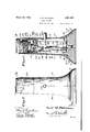
- Figure 1 is a side elevation of a cigar lighter constructed in accordance with the present invention.
- Figure 2 is a vertical section on the line 2-2 of Figure 1.
- Figure 3 is a detail perspective 'view showing the upper part of the insulating body and the lower part of the shield element of the present device in separated relation.
- Figure 4 is a detail vertical section through the upper portion ot the insulating body and 1929. Serial No. 367,323?.
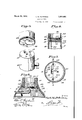
- Figure 5 is a section on the line 5 5 of Figure 2.
- This body is ot hollow construction to afford a switch chamber a within the portion 10 and a chamber a within the base 11, said chamber being of greater width than said switch chamber whereby a shoulder 13 is formed between said chambers.
- Reintorcing ribs 14, 14, formed integrally with the body A extend longitudinally of the portion l() of said body and project into the chamber a at opposite sides thereof. These ribs terminate at their lower ends flush or substantially Hush with the shoulder 13 and each of them has formed therein a recess 15 opening through the lower end and the inner side of the rib.
- a lug or key 16 is formed integrally with the body A and this lug or key projects downwardly from the shoulder 13 a short distance into the chamber a.
- a recess 2O is formed in the under ⁇ or bottom tace of the wall 12 and this recess opens at one side into a deeper recess 21, one wall of which constitutes a stop abutment 22 for a movable contact element ot the switch a section on the line 6--6 of mechanism C, which mechanism presently will be described in detail.
- a metallic screw shell 26 Disposed within this shield element is a metallic screw shell 26 which also has openings in its bottom wall to receive the pins 17. Insulation including the tubular sleeve 25 and thedisk 25a is disposed between said shield elementl and lsaid screw shell.
- the shell 26 together with the insulation k2 5-.25a and the shield element 23 are secured to the wall 12 by a screw 27 which passes vthrough alined holes in said parts and through the l opening 1-8 ⁇ and has threaded engagement with Va nut 28 seated in the recess 20.
- Said screw is insulated from the shell 26 by 4an insulating disk or washer 2 9, the head of saidscrewtlius being adapted to constitute a center contact within the shell 26, and the nut 28 being adaptedto constitute vthe iixed'contact of' the switch mechanism C previously mentioned.
- theparts 23,25, 26 and 29 When secured'tothebody Aby .the screw 27, theparts 23,25, 26 and 29 obviously are vheld against rotationfrelative to said body by the pins 17'. I i.
- Theswitch mechanism C is inclusive of a blade 30 cut or slotted to provide a spring arm 31and ⁇ bentor dished at ⁇ its lower end as lindicated at 32,.
- the side edgeportions of this bent or dished lower endportion 32 are adapted tokbef engaged in the recesses'15 as shown in 2.and 6 ofthe drawings, dishing of' said portion providing three points of contact, designated 1, 2 and 3, between the side walls of the'recesses 15 and the blade 30, whereby 'the latter is held firmly at lits Vlower endlagainst movement.
- the resistance unitY B' which is vthread,- edinto the shell 26 and whichis inclusive of a Center contact engaging the screw 27, is placed in .circuit with theline wires 38 when the handle .34 is pushed inwardly and this circuit is broken when said handle is released.
- Said backing is ⁇ formed with lsuitable Opnings for the Jreceptionrof theline wires 38 and ⁇ fastening screws 42, which latter are engageable-with threaded inserts 43,1no1dedinto thebody A at the bottoms of the ribs 14:. rlhus, when saidbacking is'secured in the chamber ait serves-to hold1 .the switch ⁇ mechanism C within the chamber a.
- a disk of insulation 45t preferably is interposedbetween the backing 41 and the body A, and both this disk and' said backing arenotched or recessed as indicated at 45 to receive 'the lug or key 16, whereby relative rotation between the body andthe backing is prevented.
- a support a. shield mounted on the upper end voi' said support and having openings near its open end, al screw shell also mounted on the support within said shield, and an electrical igniting unit having a portion tting in said screw shell and having a rim portion lying in the plane of the igniting unit substantially closing the open end of the shield and located above the openings therein,
- a body of molded insulating material outwardly fia-red at its lower end to provide a supporting base, means for mounting a resistance unit on the top of said body, a switch mechanism within said body for controlling said resistance unit, inserts molded into said body, a backing within said base, and screw means passing through said backing into said inserts detachably securing said backing to said body.
- an electrical cigar lighter a hollow ipporting body, means for mounting a resistance unit on the top of said body, a switch mechanism within said body for controlling said resistance unit, a backing holding said switch mechanism within said body, means for securing said backing to said body, and interengaging formations between said body and said backing holding said body and backing against relative rotation.
Landscapes
- Engineering & Computer Science (AREA)
- Chemical & Material Sciences (AREA)
- Combustion & Propulsion (AREA)
- Mechanical Engineering (AREA)
- General Engineering & Computer Science (AREA)
- Elimination Of Static Electricity (AREA)
Description
March 29, 1932. c, M. PETERSEN 1,851,402
C IGAR LIGHTER Filed May' 3l, 1929 2 Sheets-Sheet l l 3mm@ VWTNESSESr- Carl MP8 Z'6736TO/7 A f .5" l/ a v afkomq March 29, 1932. Q MY PETERSEN C IGAR LIGHTER Filed May 31, 1929 2 Sheets-Shree?I 2 31a/vento@ Patented Mar. 29, 1932 UNETED STATES SPATENT FFECE CARL M. PETERSEN, OF TRENTON, NEW JERSEY, ASSIGNOR TO CIRCLE F MFG. CO., OF TRENTON, NEW JERSEY, A. CORPORATION OF NEW JERSEY CIGAR LIGHTER Application led May 31,
This invention relates to cigar or cigarette lighters ot the electrical type and has particular reference to a device of the type disclosed in my prior application No. 265,151,
51 filed March 27, 1928, now Patent No.
1,762,075, issued June 3, 1930.
A general object of the invention is to provide a device of the class described which is light in weight, strong, durable, of attractive appearance, and which is thoroughly reliable and eilicient in use, thereby enhancing the device from a practical and manufacturing standpoint.
Another object of the invention is to provide a device embodying a novel casingor standard which may be made of moldable insulating material and which possesses novel structural features and characteristics which vfacilitate assembly and also contribute materially to the general usefulness and appearance of the device.
A further object of the invention is to profide a novel receptacle for receiving the heating unit, the same including a metallic guard surmounting the base or standard and having insulation and ventilation means which provide tor the safety oi the d evice in use and also protect the user against unduly heated exterior surfaces.
lilith the abo-ve and other objects in view whichwill more readily appear as the nature of the invention is better understood, the saine consists in the novel construction, combination and arrangement of parts hereinafter more fully described, illustrated and claimed.
In the drawings, wherein like characters of reference denote corresponding parts of the diiterent views:
Figure 1 is a side elevation of a cigar lighter constructed in accordance with the present invention.
Figure 2 is a vertical section on the line 2-2 of Figure 1. f Figure 3 is a detail perspective 'view showing the upper part of the insulating body and the lower part of the shield element of the present device in separated relation.
.Figure 4 is a detail vertical section through the upper portion ot the insulating body and 1929. Serial No. 367,323?.
the lower portion of the screw shell and the shield element of the present device.
Figure 5 is a section on the line 5 5 of Figure 2; and
Figure 6 is Figure 5. Referring to the drawings in detail, A designates, generally, the hollow body or supporting housing of the present lighter, B an electric resistance unit constituting the lighter proper of the present device, and C, al switch mechanism, contained within said body or housing', for controlling a circuit in which said resistance unit is included. The body A, in accordance with the present invention, is molded from insulating material, such as bakelite, into any suitable design, same being inclusive in this instance of an upright, approximately cylindrical portion 10, iared outwardly at its lower end into a relatively wide base as indicated at 11, and closed at its upper end by a wall 12. This body is ot hollow construction to afford a switch chamber a within the portion 10 and a chamber a within the base 11, said chamber being of greater width than said switch chamber whereby a shoulder 13 is formed between said chambers. Reintorcing ribs 14, 14, formed integrally with the body A, extend longitudinally of the portion l() of said body and project into the chamber a at opposite sides thereof. These ribs terminate at their lower ends flush or substantially Hush with the shoulder 13 and each of them has formed therein a recess 15 opening through the lower end and the inner side of the rib. In addition, a lug or key 16 is formed integrally with the body A and this lug or key projects downwardly from the shoulder 13 a short distance into the chamber a.
Formed integrally with the body A and projecting upwardly from the top wall 12 thereoic is a pair of pins 1'?, 17, while formed through said wall, is a central opening 18 and a slot 19 located to one side ot said central opening. A recess 2O is formed in the under` or bottom tace of the wall 12 and this recess opens at one side into a deeper recess 21, one wall of which constitutes a stop abutment 22 for a movable contact element ot the switch a section on the line 6--6 of mechanism C, which mechanism presently will be described in detail.
A cup-like shield element 23, formed from sheet metal or other suitable material, and provided with holes 24 in its bot-tom wall to receive the pins 17, rests upon the upper face of the wall 12. Disposed within this shield element is a metallic screw shell 26 which also has openings in its bottom wall to receive the pins 17. Insulation including the tubular sleeve 25 and thedisk 25a is disposed between said shield elementl and lsaid screw shell. The shell 26 together with the insulation k2 5-.25a and the shield element 23 are secured to the wall 12 by a screw 27 which passes vthrough alined holes in said parts and through the l opening 1-8` and has threaded engagement with Va nut 28 seated in the recess 20. Said screw is insulated from the shell 26 by 4an insulating disk or washer 2 9, the head of saidscrewtlius being adapted to constitute a center contact within the shell 26, and the nut 28 being adaptedto constitute vthe iixed'contact of' the switch mechanism C previously mentioned. When secured'tothebody Aby .the screw 27, theparts 23,25, 26 and 29 obviously are vheld against rotationfrelative to said body by the pins 17'. I i.
' Theswitch mechanism C is inclusive of a blade 30 cut or slotted to provide a spring arm 31and`bentor dished at `its lower end as lindicated at 32,. The side edgeportions of this bent or dished lower endportion 32 are adapted tokbef engaged in the recesses'15 as shown in 2.and 6 ofthe drawings, dishing of' said portion providing three points of contact, designated 1, 2 and 3, between the side walls of the'recesses 15 and the blade 30, whereby 'the latter is held firmly at lits Vlower endlagainst movement. Said blade extends upwardly and is of such length that its upper endis disposed within'therecess 21 for movement, by VtleXure of-thefblade, either into engagement with the stop 22 o r intocngagementwith the Contact constituted by thenut 28. An actuator33-is supportedat its innerend upon theffree upper end 4of theV spring arm 31 and at ,its outer yend is provided with a push button form of'handle 34 which is slidably mounted withinan opening formed in the side of the body A. Between said actuator andthe iree end portion of. the .blade 30 is arranged av coil spring 36 which functions, when 'the free end portion ofthe spring arm 31is movedto the left ofthe plane of the blade 30, as viewed in Fig. 2 ot the drawings, to snap the upper or ltree lend portion ofthe blade 30 against the contact-'28, and tosnap saidblade away from said contact and against the stop 22 when said-spring arm is movedv to the right ot `the plane ot said blade, as viewed in said figure'. The spring larm 31 is bentso .that normally'its upper end isk disposed to the rightron the plane ofthe blade 30 as viewed inY lfigy2, wherebythefree Vor upper'` end of said blade is disposed nor.-
mally disengaged from the contact 28 and against the stop 22, a projection 37 being formed on the actuator 33 for engagement with the side wall of the body A to limit outward movement of said actuator under the influence of the resiliency of the spring arm 31 andthe spring 36. Thus, by pushing inward on the handle 34: the blade 30 will be snapped into engagement with the Contact 28, and uponj release of pressurevagainstsaid handle the` parts will automatically-.be restored by a snap action to the status shown in Fig.V 2.
:Connected with the lower end ot the blade- 30 is one of a pair Ofiline wires 38, 38, the other of which is connected with the lower end` ot a conductor in the form of a metal strip 39whichextends from the lower end of the-*chamber a upwardly through `the slot l19, through an, opening 40 formed' in the shield 23, and through the insulating member 25 into engagement with the screw shell 26. 5A
Thus,.the resistance unitY B', which is vthread,- edinto the shell 26 and whichis inclusive of a Center contact engaging the screw 27, is placed in .circuit with theline wires 38 when the handle .34 is pushed inwardly and this circuit is broken when said handle is released.
By reference to Figs. Y-2 and 6 ot the-.drawings, it will be observedthat the bottomvoffithe body A is openl whereby the switch mechanism C is insertabl'e into and removable tromfsaid f body through the open bottom thereof. To close thebot'tom of said body 'when-theswitch mechanism 1-"has been assembled therein, a backing 41 is provided'. Thisbacking, which conforms in general-to the shapeotthe cham.- ber a', preferably is formed'. from porcelain or other insulating material ,of a-.heavy nature,v whereby it serves lto weight the baseo the .lighter to assist in maintaining same in an uprightposition. Said backing is `formed with lsuitable Opnings for the Jreceptionrof theline wires 38 and `fastening screws 42, which latter are engageable-with threaded inserts 43,1no1dedinto thebody A at the bottoms of the ribs 14:. rlhus, when saidbacking is'secured in the chamber ait serves-to hold1 .the switch` mechanism C within the chamber a. A disk of insulation 45t preferably is interposedbetween the backing 41 and the body A, and both this disk and' said backing arenotched or recessed as indicated at 45 to receive 'the lug or key 16, whereby relative rotation between the body andthe backing is prevented.
lVhen the' circuit to the resistance unitV B is kclosed considerable heat is generated by said unit, and in order to avoidresultant eX- cessive heating of the shield 2.3,fthe latter is l the shield and that the holes in the latter are disposed above said insulating member.
lWithout further description it is thought that the features and advantages of the invention will be readily apparent to those skilled in the art, and it will of course be understood that changes in the form, proportion and minor details of construction may be resorted to, without departing from the spirit ol' the invention and scope of the appended claims.
I claim:
l. In an electrical cigar lighter, a support, a. shield mounted on the upper end voi' said support and having openings near its open end, al screw shell also mounted on the support within said shield, and an electrical igniting unit having a portion tting in said screw shell and having a rim portion lying in the plane of the igniting unit substantially closing the open end of the shield and located above the openings therein,
2. ln an electrical cigar lighter, a support, a screw shell mounted on said support, a shield surrounding said screw shell and having ventilating openings, an electrical igniting unit fitted in said screw shelland having the resistance element thereof arranged above the ventilating openings in the shield, and an insulating member between said screw shell and said shield.
3. In an electrical cigar lighter, a support, a cup-like shield element mounted on said support, a screw shell disposed within said shield element, insulation between said shield element and said screw shell, and a member constitutinflV a center contact for said screw shell serving to secure said screw shell, said insulation and said shield element to said support.
4t. In an electrical cigar lighter, a body of molded insulating material outwardly fia-red at its lower end to provide a supporting base, means for mounting a resistance unit on the top of said body, a switch mechanism within said body for controlling said resistance unit, inserts molded into said body, a backing within said base, and screw means passing through said backing into said inserts detachably securing said backing to said body.
5. In an electrical cigar lighter, a hollow ipporting body, means for mounting a resistance unit on the top of said body, a switch mechanism within said body for controlling said resistance unit, a backing holding said switch mechanism within said body, means for securing said backing to said body, and interengaging formations between said body and said backing holding said body and backing against relative rotation.
CARL M. Parmesan.
Priority Applications (1)
| Application Number | Priority Date | Filing Date | Title |
|---|---|---|---|
| US367369A US1851402A (en) | 1929-05-31 | 1929-05-31 | Cigar lighter |
Applications Claiming Priority (1)
| Application Number | Priority Date | Filing Date | Title |
|---|---|---|---|
| US367369A US1851402A (en) | 1929-05-31 | 1929-05-31 | Cigar lighter |
Publications (1)
| Publication Number | Publication Date |
|---|---|
| US1851402A true US1851402A (en) | 1932-03-29 |
Family
ID=23446892
Family Applications (1)
| Application Number | Title | Priority Date | Filing Date |
|---|---|---|---|
| US367369A Expired - Lifetime US1851402A (en) | 1929-05-31 | 1929-05-31 | Cigar lighter |
Country Status (1)
| Country | Link |
|---|---|
| US (1) | US1851402A (en) |
-
1929
- 1929-05-31 US US367369A patent/US1851402A/en not_active Expired - Lifetime
Similar Documents
| Publication | Publication Date | Title |
|---|---|---|
| US2240678A (en) | Cigar and cigarette lighter | |
| US3238353A (en) | Cigar lighter | |
| US1851402A (en) | Cigar lighter | |
| US3551092A (en) | Cigarette lighting and air refreshing device | |
| US2292918A (en) | Electric cigar lighter | |
| US2275922A (en) | Cigar lighter | |
| US2180711A (en) | Cigar lighter | |
| US1983738A (en) | Cigarette lighter | |
| US1736544A (en) | Cigar lighter | |
| US1757255A (en) | Electric cigar lighter | |
| US1886461A (en) | Pocket cigar lighter | |
| US3437880A (en) | Electric gas ignitor | |
| US2244233A (en) | Electric cigar lighter | |
| US2056146A (en) | Burner starting device and wick therefor | |
| US904524A (en) | Electric lighting device. | |
| US2269394A (en) | Electric lighter for cigars, cigarettes, etc. | |
| US1908502A (en) | Electric cigar lighter | |
| US2180927A (en) | Cigar lighter | |
| US1530914A (en) | James h | |
| US2269507A (en) | Cigar lighter | |
| US1803361A (en) | Cigar lighter | |
| US2248409A (en) | Cigar lighter | |
| US1710348A (en) | Cigar lighter | |
| US1475584A (en) | Handlamp switch | |
| US1359369A (en) | Electric cigar-lighter tip |