US1851392A - Compressed air and gas blowtorch - Google Patents
Compressed air and gas blowtorch Download PDFInfo
- Publication number
- US1851392A US1851392A US521532A US52153231A US1851392A US 1851392 A US1851392 A US 1851392A US 521532 A US521532 A US 521532A US 52153231 A US52153231 A US 52153231A US 1851392 A US1851392 A US 1851392A
- Authority
- US
- United States
- Prior art keywords
- tube
- compressed air
- chamber
- gas
- air
- Prior art date
- Legal status (The legal status is an assumption and is not a legal conclusion. Google has not performed a legal analysis and makes no representation as to the accuracy of the status listed.)
- Expired - Lifetime
Links
- 230000008878 coupling Effects 0.000 description 7
- 238000010168 coupling process Methods 0.000 description 7
- 238000005859 coupling reaction Methods 0.000 description 7
- 238000010276 construction Methods 0.000 description 2
- 239000000203 mixture Substances 0.000 description 2
- 102000004726 Connectin Human genes 0.000 description 1
- 108010002947 Connectin Proteins 0.000 description 1
- 238000002485 combustion reaction Methods 0.000 description 1
- 210000002445 nipple Anatomy 0.000 description 1
Images
Classifications
-
- F—MECHANICAL ENGINEERING; LIGHTING; HEATING; WEAPONS; BLASTING
- F23—COMBUSTION APPARATUS; COMBUSTION PROCESSES
- F23D—BURNERS
- F23D14/00—Burners for combustion of a gas, e.g. of a gas stored under pressure as a liquid
- F23D14/34—Burners specially adapted for use with means for pressurising the gaseous fuel or the combustion air
Definitions
- Another object of the invention is to so construct and arrange the parts that thereis no danger of the parts exploding, and. one which can be manufactured to sell at low cost and which is not likely to get out of order and will work regardless of weather conditions, and may be used inside or outside, and is easy to handle.
- This invention also consists in certain other features of construction and in .the combination and arrangement of the several parts, to be hereinafter fully described, il-
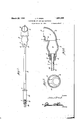
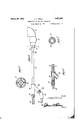
- Figure 1 is an elevation of the device.
- Fig. 2 is a section on the line 2-2 of Fig.
- Fig. 3 is a section on the line 33 of F1 Fig. 4 is a side View.
- Ahandle forming tubev 19 isthreadedinto; the adapter," and a two-part coupling 20 "is nipple 21 isthreaded in; the. straight part of. thecouplingQQ and a small tube22 hasflone end threadedinthenipplje and its other end".
- a torch of the class described comprising a head having a front chamber provided with'an outlet opening and a flat rear wall formed with air openings, and a rear'chamher having its walls tapering forwardlywith its small front end connected to said rear wall with the two" chambers incommunication with V each other,ia tube connected tothe rear end j r 7 7 l I I ofthe rear chamber, an angle coupling cono nected to the rear end of the tube, a plug closing the rear end of the straight part of the coupling, means for connecting the'plug to a source of compressed air, a small tube 3 10,
- v I p i v 195 7 means for connecting the angle part of the couplingto a-supply of gas.
- a torch of the class described comprising a head having a front chamber provided with an outletopening and an enlarged rear V v r V i g 1 1 c' part having a flat rear wall, and a rear chamher having its walls tapering forwardly with .:its small'front end connected to said rear wall with the two chambers in communication witheach other, a straight tube ofthe same internal diameter throughout connected to I the rearend ofthe rear chamber, an angle coupling-connected to'therear end of the tube,
- aplug closingthe rear end ofthe straight I v r V r f part of the coupling means for connecting the plug to a source of compressed air, axsmall outertube and engaging the front end 'of'-theo. straighttube at the same diameter throughout having. its rear end connected, with'the oo'plug and said small tube passing throughthe I V i ,7 l f f coupling and through a part of the 'first- 'mentioned tube and terminating a distance fromthe front end of the first mentioned tube, small internal projections carried bythe
Landscapes
- Engineering & Computer Science (AREA)
- Chemical & Material Sciences (AREA)
- Combustion & Propulsion (AREA)
- Mechanical Engineering (AREA)
- General Engineering & Computer Science (AREA)
- Gas Burners (AREA)
Description
March 29, 1932. J KRE|D 7 1,851,392
COMPRESSED-AIR AND GAS BLdWTORCH Inventor J07; [K746 ZZZ,
A Home y March 29, 1932. J. F. KREID COMPRESSED AIR AND GAS BLOWTORCH Filed March 10, 1951 2 Sheets-Sheet A vlilllllllltntl 7//////// Patented Mar. 29. 1932 UNETED strains 5 JOHN ranniia cx xamnoa eis tijsa ot,ta g E:
COMEEESSED ane. Ann G BLOW-TORCH Application filed March 10, 1931 Serial No. 521,532.
. head. 10
. nected to a supply of compressed air extending through the hollow handle toa point adjacent the head of the torch with means con-- necting the outer end of the hollow handle to a supply of gas whereby the air flowing from through the hollow handle into the head whereby the air and gas will be mixed together and produce an intense flame when the passage from the g V V i Y threaded to th-eouter. end of the tube 19. A 3
mixture is lighted in its Another object of the invention is to so construct and arrange the parts that thereis no danger of the parts exploding, and. one which can be manufactured to sell at low cost and which is not likely to get out of order and will work regardless of weather conditions, and may be used inside or outside, and is easy to handle. r
This invention also consists in certain other features of construction and in .the combination and arrangement of the several parts, to be hereinafter fully described, il-
lustrated in the accompanying drawings and specifically pointed out in the appended claims.
erence will be had to the accompanying draw ings, wherein l ke characters denote like or corresponding parts throughout the several 3 views, and in which Fig. 5 is a section on the line 55 of Fig. 2. 1.
Figure 1 is an elevation of the device. Fig. 2 is a section on the line 2-2 of Fig. Fig. 3 is a section on the line 33 of F1 Fig. 4 is a side View.
45 an inner chamber 10 and an outer chamber 1e cam er. havin its intermediate 11, t1 I h b 10 portion enlarged and from which enlargement the walls of the chamber taper to the point where the chamber communicates with 50 the chamber 11. This part of the head which 10 the tube into the head will act to draw gas In describing the invention in detail, refcarries thechamber l l is substantially elbow; I shaped as shown at 12 .witliits discharge 7 opening 13 at one side thereof. Said chain-,1 ber llhasa rear wall liwhich is formed with the air inlet openingsl5 so that outside 5551" air can enter the chamber l1- through these openings. An adapter 16. is threaded. into the inner end of the head and is in communication with the chamber10,.thisadapterbe- I ing held in place by the set screw 17. and its 0:; outer part is frgn med with the tool receiving 5 recesses '18.
Ahandle forming tubev 19 isthreadedinto; the adapter," and a two-part coupling 20 "is nipple 21 isthreaded in; the. straight part of. thecouplingQQ and a small tube22 hasflone end threadedinthenipplje and its other end". terminating ashort distance-in rear of the 7 ointof connection of the tube c l9 with the i l'" 1ead,.and this end is held inplace by the set screws 28 which; are adjustedtophold the when .asuitable valve eitherplaced in the ole-j i i vice itself or in the supply line isopened compressed air will flow from the hose 24' an df throughthe small pipe 22 and will then pass front the end of the pipe Q Z'thru the front endfof the tube 19 into the ChamberIO-and 90.115 due' to the escape of the streamofcompressed;1 air intotlie outlet end ot-the gas tube l9 a suctionwill be created in isaid tube19 which will draw thru the hose 27 and the rest; V of the partsintothe.tube -l9'whereithegas will mix with the compressed air inthe chamberjlQ and thenipass intokthe chamber ll" whereiit, is further mixed-with the air flowing into the chamber 11 through the my openings 15,,so-that whenthe gasislighted in 2, j v I 1 I ijss naefa as it escapes from the opening 13, an intense small iniiertube to hold the same centrally "in V flame Wlll be produced. the outer tube, and means for connectin the 7 Due to the great proport on of air'mixed angle part of the coupling to a supply gas. with the gas the combustion will be practi- In testimony whereof I aflix my signature.
' cally perfect, and the chamber 10 not only i JOHN FREDERICK KREID. 70
acts as a mixing chamber, but also as a preheating chamber due to its association with. thepart 12 containing the chamber 11. 'This arrangement of parts, also keeps the tube19, 0 which is a handle, cool. 7 V
i It is thought from the foregoing descrip tion that the advantages and novel features of the invention will be readily apparent.
' It is to be understood that changes may be made in the construction and in the combina-o v 7 v p v v v 30 made straight when desired.
ti'on and'arrangement of the several parts, provided that such changes fall within the scope" of the appended claims. It will be understood of course, that the head may be Having thus described my invention, what I claim as new is r '1. A torch of the class described comprising a head having a front chamber provided with'an outlet opening and a flat rear wall formed with air openings, and a rear'chamher having its walls tapering forwardlywith its small front end connected to said rear wall with the two" chambers incommunication with V each other,ia tube connected tothe rear end j r 7 7 l I I ofthe rear chamber, an angle coupling cono nected to the rear end of the tube, a plug closing the rear end of the straight part of the coupling, means for connecting the'plug to a source of compressed air, a small tube 3 10,
having its rear end connected with the plug a and said small tube passing through the coupling through a part of the first-mentioned tube and terminating a distance from the 40 front end of said first-mentioned tube, and, v I p i v 195 7 means for connecting the angle part of the couplingto a-supply of gas. 2."A torch of the class described comprising a head having a front chamber provided with an outletopening and an enlarged rear V v r V i g 1 1 c' part having a flat rear wall, and a rear chamher having its walls tapering forwardly with .:its small'front end connected to said rear wall with the two chambers in communication witheach other, a straight tube ofthe same internal diameter throughout connected to I the rearend ofthe rear chamber, an angle coupling-connected to'therear end of the tube,
aplug closingthe rear end ofthe straight I v r V r f part of the coupling, means for connecting the plug to a source of compressed air, axsmall outertube and engaging the front end 'of'-theo. straighttube at the same diameter throughout having. its rear end connected, with'the oo'plug and said small tube passing throughthe I V i ,7 l f f coupling and through a part of the 'first- 'mentioned tube and terminating a distance fromthe front end of the first mentioned tube, small internal projections carried bythe
Priority Applications (1)
| Application Number | Priority Date | Filing Date | Title |
|---|---|---|---|
| US521532A US1851392A (en) | 1931-03-10 | 1931-03-10 | Compressed air and gas blowtorch |
Applications Claiming Priority (1)
| Application Number | Priority Date | Filing Date | Title |
|---|---|---|---|
| US521532A US1851392A (en) | 1931-03-10 | 1931-03-10 | Compressed air and gas blowtorch |
Publications (1)
| Publication Number | Publication Date |
|---|---|
| US1851392A true US1851392A (en) | 1932-03-29 |
Family
ID=24077116
Family Applications (1)
| Application Number | Title | Priority Date | Filing Date |
|---|---|---|---|
| US521532A Expired - Lifetime US1851392A (en) | 1931-03-10 | 1931-03-10 | Compressed air and gas blowtorch |
Country Status (1)
| Country | Link |
|---|---|
| US (1) | US1851392A (en) |
Cited By (1)
| Publication number | Priority date | Publication date | Assignee | Title |
|---|---|---|---|---|
| US3116798A (en) * | 1956-04-04 | 1964-01-07 | Union Carbide Corp | Rock piercing blowpipe having internal combustion chamber |
-
1931
- 1931-03-10 US US521532A patent/US1851392A/en not_active Expired - Lifetime
Cited By (1)
| Publication number | Priority date | Publication date | Assignee | Title |
|---|---|---|---|---|
| US3116798A (en) * | 1956-04-04 | 1964-01-07 | Union Carbide Corp | Rock piercing blowpipe having internal combustion chamber |
Similar Documents
| Publication | Publication Date | Title |
|---|---|---|
| US1452258A (en) | Welding-torch tip | |
| GB1496636A (en) | High velocity burner | |
| US1512132A (en) | Gas and oil burner | |
| US2198342A (en) | Blowpipe | |
| US1851392A (en) | Compressed air and gas blowtorch | |
| US2518025A (en) | Combination oil and gas burner | |
| US1446514A (en) | Fluid-fuel burner | |
| US1831799A (en) | Gas-heated soldering iron | |
| US1316681A (en) | Combination welding and cutting torch | |
| US2461731A (en) | Preheating liquid fuel torch | |
| US2239025A (en) | Fuel burner | |
| US1098429A (en) | Oil-burner. | |
| US2213043A (en) | Blowpipe | |
| US2198341A (en) | Blowpipe | |
| US1846743A (en) | Blowpipe | |
| US2356048A (en) | Preheating torch | |
| US2502604A (en) | Heating torch | |
| US1469392A (en) | Oxyacetylene torch | |
| US2238470A (en) | Blowpipe | |
| US2052871A (en) | Blowpipe | |
| US1395846A (en) | Liquid-fuel burner | |
| US1276214A (en) | Combination welding and cutting blowpipe. | |
| US1198188A (en) | Torch. | |
| US1611067A (en) | Burner | |
| US1382655A (en) | Liquid-fuel burner |