US1851385A - Telephone system - Google Patents
Telephone system Download PDFInfo
- Publication number
- US1851385A US1851385A US541175A US54117531A US1851385A US 1851385 A US1851385 A US 1851385A US 541175 A US541175 A US 541175A US 54117531 A US54117531 A US 54117531A US 1851385 A US1851385 A US 1851385A
- Authority
- US
- United States
- Prior art keywords
- line
- lines
- station
- telephone
- attendant
- Prior art date
- Legal status (The legal status is an assumption and is not a legal conclusion. Google has not performed a legal analysis and makes no representation as to the accuracy of the status listed.)
- Expired - Lifetime
Links
- 230000011664 signaling Effects 0.000 description 15
- 238000004804 winding Methods 0.000 description 11
- 239000004020 conductor Substances 0.000 description 9
- 230000000977 initiatory effect Effects 0.000 description 9
- 238000000034 method Methods 0.000 description 3
- 230000000007 visual effect Effects 0.000 description 3
- IOYNQIMAUDJVEI-BMVIKAAMSA-N Tepraloxydim Chemical group C1C(=O)C(C(=N/OC\C=C\Cl)/CC)=C(O)CC1C1CCOCC1 IOYNQIMAUDJVEI-BMVIKAAMSA-N 0.000 description 1
- 238000004519 manufacturing process Methods 0.000 description 1
Images
Classifications
-
- H—ELECTRICITY
- H04—ELECTRIC COMMUNICATION TECHNIQUE
- H04M—TELEPHONIC COMMUNICATION
- H04M3/00—Automatic or semi-automatic exchanges
- H04M3/60—Semi-automatic systems, i.e. in which the numerical selection of the outgoing line is under the control of an operator
- H04M3/64—Arrangements for signalling the number or class of the calling line to the operator
Definitions
- This invention relates to telephone systems and more particularly to telephone systems in which magneto telephone lines are employed.
- Switchboardsin which magneto telephone "lines terminate may have either of two types form of a switchboard lamp or a mechanical- 10 indicator knows as a drop. j Where the size of such switchboards is small, it isgnot customary to have an attendant activelyon' duty at night and for this reason there is pro; vided a code alarm to signal the operator when said telephone lines originate calls.
- magneto telephone linesv have aplurality of substations connected thereto, the several subscribers on a'line being assi ned a distinctive code rin b whichfan subscriber thereon may be signalled.
- neto lines that is telephone lines having but a single substation thereon, forin that case the attendant must take partin completingthecall, and extinguishesthe line lamp at that time.
- the present invention makes use of all the advantages of the line lamp signalling arrangement in a magneto telephone system but prevents the needless burning of the'line .60 the attendant that the telephone lineis await- Such a condition, however, does not apply to individual telephone maglamp of a line where one subscriber thereon is calling another.
- the main feature of the present invention resides in providing a lampsignal for each signal station magneto telephone line and a linelamp for each multi-stationmagneto telephone line, but in connection? with the last-mentioned group of lines, switching; means are provided whereby the line lamps thereof may be disabled during any desired period of the day when the attendant is not actively on duty.
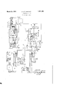
- the drawing diagramatically represents a multi-station magneto telephone .line and a single station magneto telephone line terminating at a control exchange in a switchboard provided with a plurality of cord circuitsof which one only is indicated. It' will be understood that a plurality of such tele phone lines terminate inthe exchange, al,- though only twoof them have been indi-' lou side of the magneto 5.
- tion lines are disabled, although the line lamps of individual station lines are effective at all times.
- relay 9 is actuated from grounded battery, armature and front contact of relay 7 ,continuity spring,contact and winding of relay 9, lowermost contacts of ack J, conducitor 10, winding of the pilot relay 13 to ground.
- This circuit energizes the relay 9 which locksiitself operated from grounded battery, its left hand armature, contact and winding, and, thence over conductor 10 to ground, as previously described.
- the relay 7 responds to the impulse of'the code ringing current developed by the magneto generator 5 and in the intervals when the generator is not transmitting current over the conductors 6 and 8 of the line, the armature of the relay 7 is in its normalcposition, wherein it, closes a circuit from grounded battery, armature and back contact of relay 7 right hand armature and front contact ofrelay 9, line lamp 12, individual'jto the line A, conductor 14 to ground at contacts 11 of the code alarm key, which is assumed to be in its normal position.
- the operator On noting the lighting of the lamp 152, the operator inserts the answering plug P of a cord'circuit, such as G, into the jack J whereby plug I? opens the normally closed contact-s of the jack to disconnect the relay 7 from further control of the line A and also opens the locking circuit of the, relay 9 which in turnextinguishes the line lamp 12.
- the attendant then operates listening key LK to con'nectoperators telephone setv (not shown) to the cordfcircuit taken for use and then winding, contacts 17 of the listening key LK,
- the relay 20 whenoperated, lights the disconnect lamp 21 associated-with the calling end of the cord circuit, this lamp being lighted over; a circuit. from the grounded battery, front contact and armature of-relay 20, andthence to ground over conductor 18.
- Thelighting ofsu pervisory lamps 19, and 20, is a signal to the attendant to disestalr. lish the connection by removing plugsP and, P from the jacks Jand J
- the connection is completed in the manner thus.described and then disestablishment of the connectioniseffectcdin the manner, already set forth.
- the subscriber at substation S on the line A desires to signal substation S onhis ownline.
- the call is ini; tiated by operating the magneto generator 5 at this substation to generate code ringing impulses corresponding to the designation of the subscribers station S Normally the initiation of such a call lights the line lamp 12
- the line lamp 12 re.peats the code impulses and the attendant recognizesfrom the code lighting of this lamp that the call isfor a subscriber on the same line, and therefore, does not insert the answering plug of the cord'circuit into the jack of the calling line, However, ifthe attendant'fails to recognize the code lighting of thelamp, hemay byinserting listening key LK of this cord circuit, ascertain the number of the wanted subscriber.
- an arrangement whereby it is necessary for an attendant during the night or other quiet periods to cooperate in the connection when one subscriber on a multistation line desires to converse with another subscriber on the same line.
- substations on the same line are assigned distinctive ringing codes and means are provided at the exchange in the form of a'code alarm, effective at night, and under certain conditions controlled by a code alarm key, to repeat such code rings.
- the attendant on noting such code ringing for a substation on the same line as a substation originating a call, pays no attention to it, but in the case of the inclividual line, it is essential for the operator to cooperate in the extension of the call.
- a key 24 which renders effective the code alarm and which disables the line lamps, such as 12, of the multi-station lines.
- this key is operated to reverse the condition of its contacts, contacts 11 are opened and thereby interrupt the lighting circuit for the multi-station line lamps, such as 12.
- a night alarm in the form of a bell 25 is rendered etlective at the contacts 26 of this key to awaken the attendant. With the contacts 26 closed,
- the pilot relays such as 13 and .24, are. energized to operate the night alarm.
- a code alarm buzzer 28 repeats the code which the calling subscriber generates. This buzzer has its circuit completed though the front contact and armature of the slow-releasing rei lay 29 which'relav in turn is energized from ground, its winding, contacts of the code alarm key, conductor 81, front contact and armature of relay 7 to grounded battery, and since the armature of relay; 7 followsthe code impulses, relay 29 will likewise follow these impulses and repeat the code signal.
- VVhenthe exchange is to revert to normal service, the attendant restores, the contacts of the, night alarm key 26 and the code alarm key 24 to the position shown in the drawing. This disables the night alarm and the code alarm and also renders the line lamps, such In accordance as 12,015 multi-station' lines again efiective to signal the initiation ofcalls thereon.-
- the method of signalling the attendant on the initiation of a call which comprises visually and audibly signalling the attendant on the initiation; of a call on an individual station a certain period, visually and audibly signalling the attendant during another period of the-initiation of calls over individual station lines, and audibly signalling the attendant without visual signalling during said lasts mentioned period of the initiation of calls on said multi-station lines.
- stationilines (hl-ringa certain otherperiod gaudibly signalling, saidattenda'nt in the absence of visual signalling of the initiati'onof calls over said mnlti-station lines: duringesaid "last- -mentionedperiod said audible signalling indieatihgwhena call on a, multi-stationlineis ruledntznded for-another substation 0n th-issanie- 7:
Landscapes
- Engineering & Computer Science (AREA)
- Signal Processing (AREA)
- Devices For Supply Of Signal Current (AREA)
Description
March 29, 1932. J. H. FITZGERALD TELEPHONE SYSTEM Filed June 1, 1951 INVENTOR JOHN H. FITZGERALD 9 W ATTORNEY H a m P o MUKO OF Patented 3Mar.= 29; 1932 1 United s nres PATENT. OFFICE .gJ'OI-IN H. FITZGERALD, on ROCHESTER, NEW YORK, ASsIGNoR T sTRoMBERGpARLsoN TELEPHONE MANUFACTURING COMPANY, or nocnnsmna, NEW YORK, A Conro- EATION OE NYORK.
. TELEPHONE SYSTEM Application filed June 1, 1931. SerialNo. 541,175.
This invention relates to telephone systems and more particularly to telephone systems in which magneto telephone lines are employed. Switchboardsin which magneto telephone "lines terminate may have either of two types form of a switchboard lamp or a mechanical- 10 indicator knows as a drop. j Where the size of such switchboards is small, it isgnot customary to have an attendant activelyon' duty at night and for this reason there is pro; vided a code alarm to signal the operator when said telephone lines originate calls. Frequently such magneto telephone linesv have aplurality of substations connected thereto, the several subscribers on a'line being assi ned a distinctive code rin b whichfan subscriber thereon may be signalled. In the case where a mechanical indicator or drop is used,-every call originated on a line actuates its assoclated drop so that even if one subscriber on a line code signals another sub-. scriber'on the same line, the mechanlca-l drop is actuated, and this is true in spite of the fact that such a telephone connectionis not completed at the switchboard. Since the attendant during the night period does not take any part in extending a call between subscribers on such a line, the'line drop'thereof remains in its operated position. However, where such a magneto line hasxbut a single substation thereon,theattenda-nt, even dur ing the. night, must complete the connection. In such a case, if the drops of several telephone lines have beenactuated when the subscribers on any of said lines were calling each other, then it is necessary for the attendant. to listen in onallof the magneto lines where.
the drops have been operated. Such operation materially-slows up the process of eX-.
tending an individual magneto telephone line and is generally unsatisfactory. Consequently, where a commercial source of current is available,'it is desirable to replacethe 'mechanical drops by line lamps at the switchboard. However, in such an arrangement, it
,is undesirable during the night period for the line lamp of a line to be lighted when one subscriber on that line is calling another for in that case, the attendant at the exchange recognizing from-the code call alarm that one subscriber on a line is signalling another thereon, does not attend to the connection and consequently the line lamp of that line is left burning until it is extinguished by the at-, tendant at some later time. This results in a needless use of current, materiallyreduces the life of the lampand falsely indicates to ing attention.
neto lines, that is telephone lines having but a single substation thereon, forin that case the attendant must take partin completingthecall, and extinguishesthe line lamp at that time.
The present invention makes use of all the advantages of the line lamp signalling arrangement in a magneto telephone system but prevents the needless burning of the'line .60 the attendant that the telephone lineis await- Such a condition, however, does not apply to individual telephone maglamp of a line where one subscriber thereon is calling another. p
The main feature of the present invention resides in providing a lampsignal for each signal station magneto telephone line and a linelamp for each multi-stationmagneto telephone line, but in connection? with the last-mentioned group of lines, switching; means are provided whereby the line lamps thereof may be disabled during any desired period of the day when the attendant is not actively on duty.
The drawing diagramatically represents a multi-station magneto telephone .line and a single station magneto telephone line terminating at a control exchange in a switchboard provided with a plurality of cord circuitsof which one only is indicated. It' will be understood that a plurality of such tele phone lines terminate inthe exchange, al,- though only twoof them have been indi-' lou side of the magneto 5.
tion lines are disabled, although the line lamps of individual station lines are effective at all times.
It is believed that the invention will best be understood by describing the operations involved in completing telephone calls from several types ofclines. Let it first be assumed that the subscriber S on the multistation magneto line A originates a call to subscriber onanother line, which is effected by turning the handle of'his magneto generator 5. This causesjalternating current to flow through one conductor 6, of the line, through the upper contacts of the jack J, left hand winding of the relay 7, middle contacts of the jack, conductor 8, andpthence over the other The relay 7 is energized in this circuit and closes a locking circuit for itself] through its right hand:
winding, continuity spring and contact of relay 9, front contact and armature of relay 7 to the groundedbattery. In multiple with this circuit, relay 9 is actuated from grounded battery, armature and front contact of relay 7 ,continuity spring,contact and winding of relay 9, lowermost contacts of ack J, conducitor 10, winding of the pilot relay 13 to ground. This circuit energizes the relay 9 which locksiitself operated from grounded battery, its left hand armature, contact and winding, and, thence over conductor 10 to ground, as previously described. The relay 7 itwill be understood, responds to the impulse of'the code ringing current developed by the magneto generator 5 and in the intervals when the generator is not transmitting current over the conductors 6 and 8 of the line, the armature of the relay 7 is in its normalcposition, wherein it, closes a circuit from grounded battery, armature and back contact of relay 7 right hand armature and front contact ofrelay 9, line lamp 12, individual'jto the line A, conductor 14 to ground at contacts 11 of the code alarm key, which is assumed to be in its normal position.
On noting the lighting of the lamp 152, the operator inserts the answering plug P of a cord'circuit, such as G, into the jack J whereby plug I? opens the normally closed contact-s of the jack to disconnect the relay 7 from further control of the line A and also opens the locking circuit of the, relay 9 which in turnextinguishes the line lamp 12. The attendant then operates listening key LK to con'nectoperators telephone setv (not shown) to the cordfcircuit taken for use and then winding, contacts 17 of the listening key LK,
front contact and, armature of relay 16, thence over conductor 18, to ground through the winding of re1ay40. The operationof the relay 16 lights the answering supervisory relay. 18 togive a disconnect signal. Simi? larly when the called'subscriber terminates the call, he actuatesthe magneto generator (not shown) at hissubstation, which energizcs the calling supervisory relay 2O throu h its upper winding over the two sides oft 1e called line; Relay 20, when actuated, locks itself operated from grounded battery, through its lower winding, contacts 21 of the listeningkey, front contact. and armature of relay 20. and thence over conductor 18, to ground through the winding of relay 40. The relay 20, whenoperated, lights the disconnect lamp 21 associated-with the calling end of the cord circuit, this lamp being lighted over; a circuit. from the grounded battery, front contact and armature of-relay 20, andthence to ground over conductor 18. Thelighting ofsu pervisory lamps 19, and 20, is a signal to the attendant to disestalr. lish the connection by removing plugsP and, P from the jacks Jand J When a calling subscriber S on an individual station line,,desires. to call, the, connection is completed in the manner thus.described and then disestablishment of the connectioniseffectcdin the manner, already set forth.
Let it be assumed thatthe subscriber at substation S on the line A desires to signal substation S onhis ownline. The call is ini; tiated by operating the magneto generator 5 at this substation to generate code ringing impulses corresponding to the designation of the subscribers station S Normally the initiation of such a call lights the line lamp 12 The line lamp 12 re.peats the code impulses and the attendant recognizesfrom the code lighting of this lamp that the call isfor a subscriber on the same line, and therefore, does not insert the answering plug of the cord'circuit into the jack of the calling line, However, ifthe attendant'fails to recognize the code lighting of thelamp, hemay byinserting listening key LK of this cord circuit, ascertain the number of the wanted subscriber.
In accordance with the present invention, an arrangement is provided whereby it is necessary for an attendant during the night or other quiet periods to cooperate in the connection when one subscriber on a multistation line desires to converse with another subscriber on the same line. with the usual practice, substations on the same line are assigned distinctive ringing codes and means are provided at the exchange in the form of a'code alarm, effective at night, and under certain conditions controlled by a code alarm key, to repeat such code rings. During such peroids, the attendant on noting such code ringing for a substation on the same line as a substation originating a call, pays no attention to it, but in the case of the inclividual line, it is essential for the operator to cooperate in the extension of the call.
During the night or other quiet period when it is unnecessary for the operator to cooperate in a connection between subscribers on the same line, it is, therefore, unnecessary to light the line lamp of a multi-station line and there is provided a key 24 which renders effective the code alarm and which disables the line lamps, such as 12, of the multi-station lines. When this keyis operated to reverse the condition of its contacts, contacts 11 are opened and thereby interrupt the lighting circuit for the multi-station line lamps, such as 12. At this time, a night alarm in the form of a bell 25 is rendered etlective at the contacts 26 of this key to awaken the attendant. With the contacts 26 closed,
whenever any subscriber on the exchange initiates a call on either a multi-station line or an individual line, the pilot relays, such as 13 and .24, are. energized to operate the night alarm. But in the case of multi-station lines, when any of these lines originate a call, a code alarm buzzer 28 repeats the code which the calling subscriber generates. This buzzer has its circuit completed though the front contact and armature of the slow-releasing rei lay 29 which'relav in turn is energized from ground, its winding, contacts of the code alarm key, conductor 81, front contact and armature of relay 7 to grounded battery, and since the armature of relay; 7 followsthe code impulses, relay 29 will likewise follow these impulses and repeat the code signal.
The attendant on noting from the code alarm that a subscriber is calling another station on the same line, pays no further attention to the call.
VVhenthe exchange is to revert to normal service, the attendant restores, the contacts of the, night alarm key 26 and the code alarm key 24 to the position shown in the drawing. This disables the night alarm and the code alarm and also renders the line lamps, such In accordance as 12,015 multi-station' lines again efiective to signal the initiation ofcalls thereon.-
What I claim is: l
1. In a telephone system, an operators position, multi-station linesand single station lines terminating 'atsald operators poslt on,
tive.
2; In a telephonesystem,;an'ope rators position, multi-station lines and single station lines terminating at said operators position, a l1ne lamp for each of said lines, an audible signal at said pos1t1on, andm'eans for (118- abling the lamp signals of the multi-station" lines and for substituting therefor said audi ble signal. p v
3; In a telephone system,having multi-station telephone'lines and individual station telephone lines,-terminating in an operators position, wherein calls "are originated by transmitting code impulses of alternating current which comprises actuating an illumi-' v nating signal in the case 0t calls originating on the individual station lines, and generating audible signals in accordance'with the code impulses transmitted over multi-station telephone lines.
4. Ina telephone systemprovided 'withmulti-station magneto telephone lines and individual station magneto telephonelines, the method of signalling the attendant on the initiation of a call which comprises visually and audibly signalling the attendant on the initiation; of a call on an individual station a certain period, visually and audibly signalling the attendant during another period of the-initiation of calls over individual station lines, and audibly signalling the attendant without visual signalling during said lasts mentioned period of the initiation of calls on said multi-station lines.
6. In a telephone system provided with multi-station magneto telephone lines and indlv'idual station magneto telephone lines, the
method of indicating to'an attendant that calls are being originated 'over said lines which comprises visually signallingthe attendant during a certain period of the initiation of calls over any of said telephone lines, visually and audibly'signalling said attendant of the initiation of calls over individual E Lanna;
stationilines (hl-ringa certain otherperiod gaudibly signalling, saidattenda'nt in the absence of visual signalling of the initiati'onof calls over said mnlti-station lines: duringesaid "last- -mentionedperiod said audible signalling indieatihgwhena call on a, multi-stationlineis iriintznded for-another substation 0n th-issanie- 7: In a telephone system: provided with multifstation -magneto telephone lines and=individual station magnet-o telephone lines, the, methed of indicating to an attendant: that callsare being originated over said lines; which comprises: visually signalling the at: I tendant oflthe initiationnof calls over any of said-lines during a: certain-period; saidvisual signalling being of: a distinctive character whenone-stationon a telephone line initiates a call for another station on the same line, wvisual-ly. and audibly-signallingsaid attendant of-the initiation of calls over individual station-lines during a; certain other period, audibly signalling 'said attendant in the ab: sence of visual signalling of the initiation of calls over-saidinulti-ctationlines during said last-mentioned period, said audible signallinglindicating when a call on the multi-stationline isintended for another substation on this same: line;v 30 In witness whereof, I hereunto subscribe my nanietliis 28th'day of May, D. 1931'.
JOHN H. FITZGERALD.
Priority Applications (1)
| Application Number | Priority Date | Filing Date | Title |
|---|---|---|---|
| US541175A US1851385A (en) | 1931-06-01 | 1931-06-01 | Telephone system |
Applications Claiming Priority (1)
| Application Number | Priority Date | Filing Date | Title |
|---|---|---|---|
| US541175A US1851385A (en) | 1931-06-01 | 1931-06-01 | Telephone system |
Publications (1)
| Publication Number | Publication Date |
|---|---|
| US1851385A true US1851385A (en) | 1932-03-29 |
Family
ID=24158482
Family Applications (1)
| Application Number | Title | Priority Date | Filing Date |
|---|---|---|---|
| US541175A Expired - Lifetime US1851385A (en) | 1931-06-01 | 1931-06-01 | Telephone system |
Country Status (1)
| Country | Link |
|---|---|
| US (1) | US1851385A (en) |
Cited By (1)
| Publication number | Priority date | Publication date | Assignee | Title |
|---|---|---|---|---|
| US2549688A (en) * | 1947-10-18 | 1951-04-17 | Automatic Elect Lab | Magneto party-line adapter |
-
1931
- 1931-06-01 US US541175A patent/US1851385A/en not_active Expired - Lifetime
Cited By (1)
| Publication number | Priority date | Publication date | Assignee | Title |
|---|---|---|---|---|
| US2549688A (en) * | 1947-10-18 | 1951-04-17 | Automatic Elect Lab | Magneto party-line adapter |
Similar Documents
| Publication | Publication Date | Title |
|---|---|---|
| US1851385A (en) | Telephone system | |
| US2549719A (en) | Executive's and secretary's trunk connective intercommunication and signal system | |
| US2334876A (en) | Printing telegraph system | |
| US2298489A (en) | Group-call telephone system | |
| US1700320A (en) | Telephone system | |
| US2410866A (en) | Telephone system | |
| US2332966A (en) | Code call system | |
| US2693507A (en) | Automatic telephone system | |
| US1501287A (en) | Automatic telephone system | |
| US1697623A (en) | Telephone system | |
| US2210739A (en) | Through supervision system | |
| US1261492A (en) | Telephone system. | |
| US1615935A (en) | Manual telephone system | |
| US1944961A (en) | Telephone system | |
| US1107133A (en) | Telephone-exchange system. | |
| US1802449A (en) | Telephone system | |
| US2201358A (en) | Common battery cord circuit | |
| US1943402A (en) | Telephone system | |
| US2042828A (en) | Telephone system | |
| USRE15774E (en) | Telephone system | |
| US1842659A (en) | Telephone system | |
| US1821193A (en) | Telephone system | |
| US2667539A (en) | Automatic telephone connector circuit | |
| US1238748A (en) | Multi-exchange telephone system. | |
| US1632051A (en) | Telephone system |