US1851373A - Nozzle tip holder - Google Patents
Nozzle tip holder Download PDFInfo
- Publication number
- US1851373A US1851373A US420184A US42018430A US1851373A US 1851373 A US1851373 A US 1851373A US 420184 A US420184 A US 420184A US 42018430 A US42018430 A US 42018430A US 1851373 A US1851373 A US 1851373A
- Authority
- US
- United States
- Prior art keywords
- post
- nozzle
- nozzle tip
- cross bar
- slot
- Prior art date
- Legal status (The legal status is an assumption and is not a legal conclusion. Google has not performed a legal analysis and makes no representation as to the accuracy of the status listed.)
- Expired - Lifetime
Links
- 238000003780 insertion Methods 0.000 description 2
- 230000037431 insertion Effects 0.000 description 2
- 238000010276 construction Methods 0.000 description 1
- 230000000994 depressogenic effect Effects 0.000 description 1
- 239000002184 metal Substances 0.000 description 1
- 238000012986 modification Methods 0.000 description 1
- 230000004048 modification Effects 0.000 description 1
- 230000009972 noncorrosive effect Effects 0.000 description 1
- 239000007787 solid Substances 0.000 description 1
Images
Classifications
-
- A—HUMAN NECESSITIES
- A62—LIFE-SAVING; FIRE-FIGHTING
- A62C—FIRE-FIGHTING
- A62C31/00—Delivery of fire-extinguishing material
- A62C31/005—Delivery of fire-extinguishing material using nozzles
Definitions
- Anjobject of the invention is to provide a holder that permits the supporting of reducing nozzles of various sizes for storage or transportation in such a manner that they may be removed from the holders with ease and dispatch when needed while being normally held securely thereon.
- Fig. 2 is a vertical transverse sectional View 1 through Figure 1;
- Fig. 3 is an enlarged sectional View taken through'the-upper end of the holder.
- 4 indicates generallya solid post preferably formed of non-corrosive metal. It tapers from near its lower to its upper end.
- the upper end of the post may be modified as desired, having in mind that the post is to receive the nozzle 5 circumposed thereover with the discharge end 6 ofthe nozzle adjacent the outer end of the post ⁇ a fragmentary detailed
- the upper end of the post 4 is formed with an axially extending slot 7, within which is pivotedintermediate its ends a bar
- the pivot consists of a pin 9 which extends through an opening intermediate the endsof the bar 8 andithe ends .ofthepivotare secured through the walls of the post onopposite sides of the slot 7.
- a cross bar 13 extends throughand is carried slidablyinthe slot 10, It isformed on veach end with an upstanding lipil, 15.
- the channel .12 is a ⁇ helical coiledspring 21', the upper end of which is disposed about the lug 16' on the lower end ofthe'crossbarjl3and the'lower end of which is disposed against thefinner end ofthe bolt. 1?.
- a nozzle placed upon the post in thejmanner described will be yieldably held betwe-enlthecrossbar l3 andthe pivoted retaining bar8 against.
- the nozzle To detachthenozzle5 from the pbsition n the .holder shown in Fig, 1, the nozzle is gripped in one hand and pressed inwardly. The lower end of the nozzle being in engagement with the cross bar 13 will move the cross bar inwardly against the action of the 5 spring 21. When the nozzle has been pressed inwardly far enough to permit the bar 8 to be rotated on its pivot, within the slot 7 so as to be substantially axially alined with the slot and post, the nozzle may be removed from 10 the post 4.
- the fastening bar 8 is swung into axial alinement in the slot 7 and the nozzle then passed over the outer end of the post, into place with its large end on the cross bar 13, the cross bar is then depressed against the action of the spring 21 in the bore 12 by pushing on the nozzle, until the retaining bar 8 is freed to swing to the transverse position, whereupon pressure upon the nozzle is released.
- a nozzle tip holder comprising a post having longitudinally spaced slots therein, means for securing the post on a support, said post adapted for insertion through the nozzle tip, a cross bar pivotally mounted in one of the slots for engagement by the nozzle,
- transversely disposed cross bar mounted in the other slot for longitudinal sliding movement on the post and engageable with the nozzle tip, and resilient means engaged with the last named cross bar for yielding- 1y urging the nozzle tip toward the first named cross bar.
- a nozzle tip holder comprising a post adapted for insertion through the nozzle tip and having aslot adjacent one end and further having a longitudinal bore communicating with the slot from saidione end, a threaded shank anchored in the bore and projecting from'the post, a nut threaded on the shank and, in conjunction with said shank, constituting means for securing the post on a support, a cross bar extending transversely through the slot for longitudinal sliding movement on the post and engageable with one end of the nozzle tip, a
Landscapes
- Health & Medical Sciences (AREA)
- Public Health (AREA)
- Business, Economics & Management (AREA)
- Emergency Management (AREA)
- Preliminary Treatment Of Fibers (AREA)
Description
March 29,1932. E. \D. REMVILLARD 1,851,373 I NOZZLE TIP HOLDER l iled Jan. 11. 1930 Patented ill/lair; 29, 1932 was rares- EDGAR D. .BEIwZILLAED, OF WILLIAM STOWN, .MASSACHUSETTS NOZZLE rInHoLnnn Application filed January 11, .1930. Serial No. 420,185 1 This invention relates to a support for tubular objects, and is particularly adapted for supportingreducing nozzle tips, on fire apparatus.
Anjobject of the invention is to provide a holder that permits the supporting of reducing nozzles of various sizes for storage or transportation in such a manner that they may be removed from the holders with ease and dispatch when needed while being normally held securely thereon.
Further objects of the, invention are toprovide a device of the character referred to,
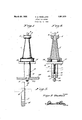
view, the invention consists of a novel construction, combination and. arrangement of parts which will be'hereinafter more specifically described and illustrated in the accompanying drawings, wherein isdisclosed an embodiment of the invention, but it is to be understood that changes, variations, and modifications may be resorted to without departing fromthe spirit-of the invention and the scope of claims hereto appended. in the drawings wherein like reference characters designate like, parts throughout the severalviews Figure 1 is a side elevational View of a nozzle holder in accordancewith the present in- Vention, showing :a reducing nozzle tip supported thereon.
Fig. 2 is a vertical transverse sectional View 1 through Figure 1;
. Fig. 3 is an enlarged sectional View taken through'the-upper end of the holder.
Referring to the drawings in detail, 4 indicates generallya solid post preferably formed of non-corrosive metal. It tapers from near its lower to its upper end. The upper end of the post may be modified as desired, having in mind that the post is to receive the nozzle 5 circumposed thereover with the discharge end 6 ofthe nozzle adjacent the outer end of the post} a fragmentary detailed The upper end of the post 4 is formed with an axially extending slot 7, within which is pivotedintermediate its ends a bar The pivot consists of a pin 9 which extends through an opening intermediate the endsof the bar 8 andithe ends .ofthepivotare secured through the walls of the post onopposite sides of the slot 7.
. The fastening bar v.8 when turned trans versely of the axis, of the post asshownfin' dotted lines in Fig; 3 ofthe drawings,,extend s across the discharge end 6 of the nozzle and holds the nozzle firmly in place as will be presently described.
Adjacent the lower endo'fthe post 4: there isformed an axially extending. slot 10 in com-. munication With; a" bore :12 which extends along the axis of the postfrom the lower end thereof. A cross bar 13 extends throughand is carried slidablyinthe slot 10, It isformed on veach end with an upstanding lipil, 15.
intermediate the ends ofthe crossbar 13, there is formed a depending, cyli ndrical-. shaped lug 16 that rides in thejcircular guide channel or bore 12. A shank of a bolt 17 is anchored in the lower end or] the channell2,
by means of the pin 18. The free end of the bolt shank'which projects below the'post 4--is threaded as at 19 to receivethe nut-20.;
Confined in; the channel .12 is a {helical coiledspring 21', the upper end of which is disposed about the lug 16' on the lower end ofthe'crossbarjl3and the'lower end of which is disposed against thefinner end ofthe bolt. 1?. By means of this arrangement a nozzle placed upon the post in thejmanner described will be yieldably held betwe-enlthecrossbar l3 andthe pivoted retaining bar8 against. falling from the post and rattling The post 4; 1nay.be attac'hedtoa shelf orrunning board or the like of the conventional the apparatus indicated at 22by simply horing a hole 23 therethrough to receivezth e threaded projecting end ofthe bolt17', and then screwing of the nut 20 on the threaded per f tion 19 into tight abutment with the lower face ofthe shelf or runningjboar'df22'or the like.
= To detachthenozzle5 from the pbsition n the .holder shown in Fig, 1, the nozzle is gripped in one hand and pressed inwardly. The lower end of the nozzle being in engagement with the cross bar 13 will move the cross bar inwardly against the action of the 5 spring 21. When the nozzle has been pressed inwardly far enough to permit the bar 8 to be rotated on its pivot, within the slot 7 so as to be substantially axially alined with the slot and post, the nozzle may be removed from 10 the post 4. To replace the nozzle on the holder the fastening bar 8 is swung into axial alinement in the slot 7 and the nozzle then passed over the outer end of the post, into place with its large end on the cross bar 13, the cross bar is then depressed against the action of the spring 21 in the bore 12 by pushing on the nozzle, until the retaining bar 8 is freed to swing to the transverse position, whereupon pressure upon the nozzle is released.
It is to be understood that by describing in detail herein, any particular form, structure, or arrangement, it is not intended to limit the invention beyond the scope of the 25 several claims, or the requirements, of the prior art.
Having thus described my invention, what I claim as new is a a 1. A nozzle tip holder comprising a post having longitudinally spaced slots therein, means for securing the post on a support, said post adapted for insertion through the nozzle tip, a cross bar pivotally mounted in one of the slots for engagement by the nozzle,
a transversely disposed cross bar mounted in the other slot for longitudinal sliding movement on the post and engageable with the nozzle tip, and resilient means engaged with the last named cross bar for yielding- 1y urging the nozzle tip toward the first named cross bar.
2. A nozzle tip holder comprising a post adapted for insertion through the nozzle tip and having aslot adjacent one end and further having a longitudinal bore communicating with the slot from saidione end, a threaded shank anchored in the bore and projecting from'the post, a nut threaded on the shank and, in conjunction with said shank, constituting means for securing the post on a support, a cross bar extending transversely through the slot for longitudinal sliding movement on the post and engageable with one end of the nozzle tip, a
5 coil spring mounted in the post having one end engaged with the shank and its other end engaged with the cross bar for yieldingly urging the cross bar toward the free end of the post, and means on the free end portion of the post for engagement with the, other end of the nozzle tip for co-action with the cross bar for retaining the nozzle tip on the post.
In testimony whereof I affix my signature.
a EDGAR n. REMI'LLARD.
Priority Applications (1)
| Application Number | Priority Date | Filing Date | Title |
|---|---|---|---|
| US420184A US1851373A (en) | 1930-01-11 | 1930-01-11 | Nozzle tip holder |
Applications Claiming Priority (1)
| Application Number | Priority Date | Filing Date | Title |
|---|---|---|---|
| US420184A US1851373A (en) | 1930-01-11 | 1930-01-11 | Nozzle tip holder |
Publications (1)
| Publication Number | Publication Date |
|---|---|
| US1851373A true US1851373A (en) | 1932-03-29 |
Family
ID=23665421
Family Applications (1)
| Application Number | Title | Priority Date | Filing Date |
|---|---|---|---|
| US420184A Expired - Lifetime US1851373A (en) | 1930-01-11 | 1930-01-11 | Nozzle tip holder |
Country Status (1)
| Country | Link |
|---|---|
| US (1) | US1851373A (en) |
Cited By (4)
| Publication number | Priority date | Publication date | Assignee | Title |
|---|---|---|---|---|
| US2827253A (en) * | 1955-11-28 | 1958-03-18 | Harold A Nelson | Hose nozzle holder |
| US4973023A (en) * | 1990-01-23 | 1990-11-27 | Neill Edward L O | Low profile security device for appliances |
| US20140065272A1 (en) * | 2012-08-31 | 2014-03-06 | Jan Folkmar | Nozzle panel |
| US20160199862A1 (en) * | 2013-08-22 | 2016-07-14 | Altachem Nv | Foam gun |
-
1930
- 1930-01-11 US US420184A patent/US1851373A/en not_active Expired - Lifetime
Cited By (4)
| Publication number | Priority date | Publication date | Assignee | Title |
|---|---|---|---|---|
| US2827253A (en) * | 1955-11-28 | 1958-03-18 | Harold A Nelson | Hose nozzle holder |
| US4973023A (en) * | 1990-01-23 | 1990-11-27 | Neill Edward L O | Low profile security device for appliances |
| US20140065272A1 (en) * | 2012-08-31 | 2014-03-06 | Jan Folkmar | Nozzle panel |
| US20160199862A1 (en) * | 2013-08-22 | 2016-07-14 | Altachem Nv | Foam gun |
Similar Documents
| Publication | Publication Date | Title |
|---|---|---|
| US499444A (en) | Bolt for attaching articles to walls | |
| US1851373A (en) | Nozzle tip holder | |
| US2658541A (en) | Hacksaw frame with spare blade storage chamber | |
| US2131676A (en) | Tooth cleaning device | |
| US3193168A (en) | Device for fixing objects | |
| US2067165A (en) | Fishing line float | |
| US248681A (en) | Geoege waltee | |
| US991426A (en) | Toggle-bolt. | |
| US2943833A (en) | Hose holder | |
| US1027525A (en) | Scarf-pin retainer. | |
| US1182160A (en) | Cue-tip. | |
| US863184A (en) | Socket-securing device for lasts. | |
| US673430A (en) | Broom-holder. | |
| US2078897A (en) | Heddle frame | |
| DE591435C (en) | Cigar tip with outwardly springy holding spike | |
| US1702873A (en) | Kitchen reminder | |
| DE612087C (en) | Device for storing, driving in and pulling out thumbtacks | |
| US1136094A (en) | Eraser-holder for pencils. | |
| DE338408C (en) | Pen with movable refill | |
| US1853686A (en) | Tension device for yarns | |
| US2475305A (en) | Apparatus for wrapping fishing rods and the like | |
| US1123807A (en) | Detachable tip for billiard-cues. | |
| US1210763A (en) | Combined staging-clamp and shingle-bracket. | |
| US1105663A (en) | Gas-lighter. | |
| DE497949C (en) | Fountain pen with ink filling device |