US1851372A - Marking gauge for doorlocks, etc. - Google Patents
Marking gauge for doorlocks, etc. Download PDFInfo
- Publication number
- US1851372A US1851372A US468027A US46802730A US1851372A US 1851372 A US1851372 A US 1851372A US 468027 A US468027 A US 468027A US 46802730 A US46802730 A US 46802730A US 1851372 A US1851372 A US 1851372A
- Authority
- US
- United States
- Prior art keywords
- spurs
- spur
- groove
- gauge
- holder
- Prior art date
- Legal status (The legal status is an assumption and is not a legal conclusion. Google has not performed a legal analysis and makes no representation as to the accuracy of the status listed.)
- Expired - Lifetime
Links
Images
Classifications
-
- B—PERFORMING OPERATIONS; TRANSPORTING
- B25—HAND TOOLS; PORTABLE POWER-DRIVEN TOOLS; MANIPULATORS
- B25H—WORKSHOP EQUIPMENT, e.g. FOR MARKING-OUT WORK; STORAGE MEANS FOR WORKSHOPS
- B25H7/00—Marking-out or setting-out work
- B25H7/04—Devices, e.g. scribers, for marking
Definitions
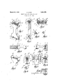
- Fig. 1 is a perspective view of one form of gauge embodying this invention
- Fig. '2 is in part side elevation and-in part a longitudinal section of this gauge ;
- Fig. 3 is an end elevation or'plan ofthegauge;
- Fig. 4 is a perspective view of one of the spurs with which this gauge is equipped;
- Fig. 5 is a perspective view pf one ofthe slides or binders by which the spurs respectiv v e mad 'f st;
- Fig. .8 is a perspective view of one end of another form of gauge containing the same gene a p in ipl with ad ti nal mp ved features;-
- Fig. -9 is a longitudinal section of the auge shown in. F g
- Fig.10 is a perspective view of one of the it spurs used in the. form f gauggzlast Q bed;
- I I p i I is a Uberlevation of one d f anotherform' o f- 'gauge containing some of the same principles;
- a door (Figifi) for the lock receiving Fig.f12 is a section on line of p Fig. 11; i a
- a slot or, groove t textendingalong the wider dimension of the holder having bounding faces which extend at an inclination to one another inwardly from the end face of the holder.
- Theinterioror bottom'part of the groove is preferably cylindrical for convenience of f part of the groove, and apertured to receive a screw 7 which enters a tapped hole in the i e of he a jac sli e lo k and mes es shoulders, such as those shown at 8 and 9 in the drawings, to eifectagripping friction with the block 5 and the base 6 of the spur, by the action of the clamping screw 7, in order that these parts may serve as a clamp to secure the spur in place.
- Each spur may thus be adjusted independently of the other, whereby they may easily be set at any desired distance apart and at any desired distance from the ends of the groove.
- Guide plates 10, 10 are secured to the opposite sides of the holder at one end across the ends of the groove 4 therein to close the latter, and they project from such end in the same general direction as the spurs, but to a greater extent, whereby to overlap the edges of a door or other piece in which a mortise is to be cut, and enable either plate to serve as a guiding means for the spurs in marking the door, etc.
- These guide plates are detachable, or at least one of them is, to permit removal of one of them when the door to :0 be marked is thicker than the width between the two plates. They may be secured to the holder 'by screws 11, or by other suitable means, as later described.
- the ends of the groove in the other end of the holder are ⁇ .3 blocked or obstructed by suitable means which do not extend beyond the extremity of the holder, and so do not offer any obstruction to use of that end of the holder in a recessed angle, such as the angle between the side and to shoulder of a doorjamb.
- Such closing means may be ofany suitable character, an illustrative means for this purpose shown here being a screw 12 which is set into a tapped and countersunk hole in the side of the holder, with its head overlapping the groove and the outer surface of the head flush with the side of the holder.
- each of the grooves are provided in each of the grooves. All on of those in the tool shown in Figs. 1- are alike. Their outer faces 13 may be plane and parallel to one another, the bevel 14 necessary to make the cutting edge or point being altoare complementally so formed as to leave beveled in order to ensure a close fit of the plate which is to be set in the recess afterwards chiseled out between the shoulders located and cut by the spurs.
- Each has an extension 15 from the end opposite to the cutting edge, the inner surface 16 of which is in thesame plane with the outer face 13 of the spur proper. These extensions serve as gauging means by which the distance apart of the cutting edges may be accurately set in con- 7 formity with the width of a lock face plate or strikerplate, or other article for which a mortise is to be prepared.
- one of the spurs is located at a distance from one of the guide plates 10 equal to the distance by which one edge of the face plate of the lock is to be separated from the adjacent side of the door. Facility in thus locating the spur is afforded by a scale 17 applied to or cut or etched in the holder adjacent to the edge of the spur receiving slot. The other spur is then set at a distance from the first one equal to the width of the lock plate.
- This distance can be most readily found by placing the lock plate between the spurs with one edge against the 95 extension 15 of the spur first located, and then moving up the second spur till its cxtension bears on the opposite edge of the plate. Or the second spur may be located by reference to the scale. Then the tool is placed against the edge of the door, being grasped by the hand of the operator with the selected guide plate against the side of the door and the ends of the spurs against its edge face, and the tool is moved along the face of the door, while being pressed against it, at'the location where the lock is to be applied. The tool may be manipulated in this way'two or more times until the incisions have been made deep enough. Either guide plate may be used as the guiding element at such times, and the other plate may be removed if the thickness or width of the door is excessive.
- spurs may be so set with reference to the gether at the inner side of the spur; but pref- Y scale 17 at the adjacent end of the tool body c5 erably the outer faces 13 are also slightly and the space between them determined by it) thespur extensions in contact with the edges.
- the gauging member 15a crosses a notch in the spur midway between its two points. But the contact surface of this gauge is in the same planewith the outer face of the spur, and the sharpening bevels of-the incis' ing points are on the inner side of the spur, as first described.
- The, spur also has base 6 and is associated with'the slide block and securing screw 7, as previously described. The two spurs of this type are located and used in the same way as already described.
- the guideplates a project to either side beyond each spur point.
- the body is the same as that first described, and the end, not shown in Figs. 8 and 9, is like the end which is shown, except that it has no guide plates. and it carries spurs like that showninFigs. 9 and 10.
- Figs. Hand 12 wherein the groove containing the spurs is made as a slot extending laterally through the holder from side to side near its end instead of entering from the end.
- the clamping means for the spurs consists of screws 18, the shanks of which pass from the narrower side of the slot into the bases of the respectively adjacent spurs and theheads of which are entirely at one side of the holder and overlap the edges of :the
- the spurs 21 are identical in principle with those previously described, having tapered bases 6a and gauging extensions and differ only in form and location.
- the guide plates 10b and 100 are also in principle likethose previously described, but with dif-- ferences in form and mode of application.
- the plate 106 is permanently secured to the sir-ed.
- the detachable plate has resilient engaging means for securing it on the body.
- This attaching means for the plate is not exclusive to the form of tool last 7 described, but is generic, and equally applicable to the forms first described, and other equivalent embodiments of the invention.
- the spurs are not mere scratching points, but are made with cutting edges extending from their points or extremitiesat a sharp ly acute angle to, and in-approximately the same plane with, the line in which the spur is movedwhen being used for the purposes described.
- the spur is enabled to ride over and cut across the grain of the wood whenever the grain, as usually is the case,
- Themanner of operation is'the same for all forms of tool here shown, and for other possible embodiments of the invention.
- the tools of Figs; 1 and 8 have the advantageover that of Fig. 11 in that their spurs are not obscured by the body, but are visible when in use and the depth to which they penetrate the wood can be observed.
- the tool shown in Figs. 8 and 9 has the further advantage that it can be used on both left hand and right hand swinging doors with the same setting ,7
- a gauge COIIlPllSlIlg l holder or body having a groove extending lengthwise in one end, spurs having bases fitted against opposite boundaries of said groove to slide therein, and means for clamping said bases against said boundaries.
- a tool of the character described comprising a body having a groove extending across one end, spurs formed withbases fitted slidingly to the sides of said groove and with points. extending jaway'from the body, and clamping means for effecting a gripping engagement of the opposite boundaries of the groove with the adjacent faces of the spur bases to secure the spurs in their adjusted. positions.
- a gauge comprising'a body having a groove, two spurs having Cutting edges and being provided with bases fitted slidingly to the walls of said groove, and means for clamping said bases in the groove, said spurs having gauging extensions the inner faces respectively of which are at the same distance apart as the cutting edges of the spurs, adapted to receive between them a body for determining the distance apart from one another at which the spurs are set.
- a gauge the character described comprising a body having an open groove at its end extendin along the width dimension of the body, a slide block fitted in said groove,
- spur having a base fitted to the entrance part of the groove, and releasable means for drawing said block and base toward one another, the boundary of the groove having a shoulder entering between the block and base whereby the spur may be clamped.
- a gauge of the character described comprising a body having a guideway, spurs mounted for travel and adjustment along said guideway, means for clamping said spurs in various positions along the guideway, and gauging projections on the spurs, the inner faces of which are parallel to one another and always at the same distance apart as the cutter edges of the spurs.
- a gauge for the purpose described comprising a body, and spurs mounted at one end of the body between the boundaries of the end face thereof with their points projecting longitudinally beyond such end and laterally beyond the adjacent side face of the body, so that said points are unobscured by the body when being used.
- a gauging tool of the character set forth comprising a body having a relatively narrow shank or waist portion and widened ends, each of said ends having a guideway extending along the wider dimension thereof, combined with spurs fitted to slide independently of one another in said guideways, and clamping means for securing the spurs in frictional gripping engagement with the boundaries of the guideways.
- a gauging tool of the character set forth comprising a body having greater length than width and greater width than thickness
- said body having at each end a groove extending along the width dimension thereof and formed with side boundaries inclined to one another, two spurs having bases fitted in each of said grooves and adapted to be adjusted slidingly along the grooves toward and away from one another, means for effecting a gripping contact between the sides of each groove and the contiguous sides of the spur bases therein, the intermediate part of the body between its ends being narrowed to furnish a handle portion whereby the body may be grasped by the user with either end projectingifrom the grasping digits for c0nvenient manipulation in incising a structure to be marked by means of said spurs.
- a gauging tool of the character described comprising a body having a handle portion adapted to be grasped in the hand of the user and a widened end portion of which the width is greater than its thickness, said end portion having a groove extending in the direction of its Wider dimension, spurs provided with bases to engage the opposite boundaries of said groove, means for forcing the sides of said bases and contiguous boundaries of the grooves into gripping contact with one another whereby to secure the spurs in adjusted position.
- a spur for use as the cutting element of a gauge of the character described comprising a base, two cutting points in a plane substantially perpendicular to the base and divergently inclined to one another at the same side of the base, said spur having a notch between said points and a gauging extension crossing said notch, the inner face of which extension is in substantially the same plane as the cutting edges of the spur.
Landscapes
- Engineering & Computer Science (AREA)
- Mechanical Engineering (AREA)
- Dovetailed Work, And Nailing Machines And Stapling Machines For Wood (AREA)
Description
March 29, 1932. s RAY 1,851,372
MARKING GAUGE FOR DOORLOCKS, ETC
Filed July 15, 1950 Patented Mar. .29; 1932.
I UwirsnsTATEs PATENT? orrice FR-ED331315.- sex-9r memos m s asnvsarrs MAEKINQ sieves r a noqsncc s ,ETC-
Appligationfiled July 15,
of the cooperating striker plates. Its object is to furnish an improved implement of this character of simple and inexpensive con- 10 struction, whereby it canabesup-pliedto users at a moderate price, to provide such implement improved means whereby the spurs thereof +may" be adjusted quickly and flaccuratelyto the width of a striker plate orof 15 the face plate of'a lock, to make the same gauge available for. operationon doors which swing from either the right hand or hand side of the doorway, tolocate marking spurs on the holder or :bodyportion of the gauge where they are llnObSCLl IQCl by such holder orbody when put to use, and to pro- 7 vide spurs capable {both of riding over and cutting, rather than following, the grain oat the wood and of inc'ising the wood to the full 25 depth required of a recess ftoreceive alock face plate .or a striker-plate so that the carpenter may thereupon 5 complete the, recess by Hchiseling out the wood between parallelincisions made by such spurs,- without having to; deepen the incisions by his chisel or any other tool. r V
vThe invention consists in the novel feae tures hereinafter described: by which the foregoing, and related objects are. accomplished and in all substantial equivalents of the features and means so disclosed.
In the drawings,+. i v Fig. 1 is a perspective view of one form of gauge embodying this invention;
Fig. '2 is in part side elevation and-in part a longitudinal section of this gauge ;Fig. 3 is an end elevation or'plan ofthegauge; i
Fig. 4 is a perspective view of one of the spurs with which this gauge is equipped;
Fig. 5 is a perspective view pf one ofthe slides or binders by which the spurs respectiv v e mad 'f st;
ig v6 an re di grams llu t i g the ann of us ofthe gauge o ma k the edge 1930. SerialNo. 468,927.
mortise, and the side of a door jamb (Fig. 7) for the -mortise inwhichthe striker plate is received; a
Fig. .8 is a perspective view of one end of another form of gauge containing the same gene a p in ipl with ad ti nal mp ved features;-
Fig. -9 is a longitudinal section of the auge shown in. F g
Fig.10 is a perspective view of one of the it spurs used in the. form f gauggzlast Q bed; I I p i I is a ideelevation of one d f anotherform' o f- 'gauge containing some of the same principles;
Of a door (Figifi) for the lock receiving Fig.f12 is a section on line of p Fig. 11; i a
[Like referencecharacters designate the same partszwhe ever they occur in all the 'D S mbing the form of gauge shown Q in Figs. 1-.4' inclusive it comprises a holder .orybo'dy Lon each opposite-end of which .two spurs 2; g are mounted. This body serves asa handlefland is made with arela- 1 tively narrow shank or waist portion for convenience of grasping and manipulation, and with widenedendsito; receive the spurs and afford suflicjient range of adjust thereof.
lnieachyend of the holder there is a slot or, groove textendingalong the wider dimension of the holder having bounding faces which extend at an inclination to one another inwardly from the end face of the holder. Theinterioror bottom'part of the groove is preferably cylindrical for convenience of f part of the groove, and apertured to receive a screw 7 which enters a tapped hole in the i e of he a jac sli e lo k and mes es shoulders, such as those shown at 8 and 9 in the drawings, to eifectagripping friction with the block 5 and the base 6 of the spur, by the action of the clamping screw 7, in order that these parts may serve as a clamp to secure the spur in place. It is also within my contemplation to provide other forms of clamping means for the same purpose, wherefore the illustrated construction is not to be construed as a limitation of the broader protection which I seek. Each spur may thus be adjusted independently of the other, whereby they may easily be set at any desired distance apart and at any desired distance from the ends of the groove.
To spurs with their holding and clamping slides are provided in each of the grooves. All on of those in the tool shown in Figs. 1- are alike. Their outer faces 13 may be plane and parallel to one another, the bevel 14 necessary to make the cutting edge or point being altoare complementally so formed as to leave beveled in order to ensure a close fit of the plate which is to be set in the recess afterwards chiseled out between the shoulders located and cut by the spurs. Each has an extension 15 from the end opposite to the cutting edge, the inner surface 16 of which is in thesame plane with the outer face 13 of the spur proper. These extensions serve as gauging means by which the distance apart of the cutting edges may be accurately set in con- 7 formity with the width of a lock face plate or strikerplate, or other article for which a mortise is to be prepared.
The use ofthe tool will be readily understood from a brief description in connection with the diagram Figures 6 and 7. In marking the location of the lock receiving mortise in a door A (Fig. 6), one of the spurs is located at a distance from one of the guide plates 10 equal to the distance by which one edge of the face plate of the lock is to be separated from the adjacent side of the door. Facility in thus locating the spur is afforded by a scale 17 applied to or cut or etched in the holder adjacent to the edge of the spur receiving slot. The other spur is then set at a distance from the first one equal to the width of the lock plate. This distance can be most readily found by placing the lock plate between the spurs with one edge against the 95 extension 15 of the spur first located, and then moving up the second spur till its cxtension bears on the opposite edge of the plate. Or the second spur may be located by reference to the scale. Then the tool is placed against the edge of the door, being grasped by the hand of the operator with the selected guide plate against the side of the door and the ends of the spurs against its edge face, and the tool is moved along the face of the door, while being pressed against it, at'the location where the lock is to be applied. The tool may be manipulated in this way'two or more times until the incisions have been made deep enough. Either guide plate may be used as the guiding element at such times, and the other plate may be removed if the thickness or width of the door is excessive.
and the door when the latter is closed, and 5555 the other spur is set at the distance therefrom equal to the width of the striker plate. These spurs may be so set with reference to the gether at the inner side of the spur; but pref- Y scale 17 at the adjacent end of the tool body c5 erably the outer faces 13 are also slightly and the space between them determined by it) thespur extensions in contact with the edges. I
of the striker platen p I The modified form of gauge shown in Figs.
8, 9 and 10 difiers from that described only in body, and to a sufiicient distance from theend of the body to enable either point .to be used when the corresponding side of the body is turned, toward the surface to be marked. The gauging member 15a crosses a notch in the spur midway between its two points. But the contact surface of this gauge is in the same planewith the outer face of the spur, and the sharpening bevels of-the incis' ing points are on the inner side of the spur, as first described. The, spur also has base 6 and is associated with'the slide block and securing screw 7, as previously described. The two spurs of this type are located and used in the same way as already described.
The guideplates a project to either side beyond each spur point. The body is the same as that first described, and the end, not shown in Figs. 8 and 9, is like the end which is shown, except that it has no guide plates. and it carries spurs like that showninFigs. 9 and 10.
Still another form of the invention is shown in Figs. Hand 12 wherein the groove containing the spurs is made as a slot extending laterally through the holder from side to side near its end instead of entering from the end. The clamping means for the spurs consists of screws 18, the shanks of which pass from the narrower side of the slot into the bases of the respectively adjacent spurs and theheads of which are entirely at one side of the holder and overlap the edges of :the
7 slot. The spurs 21 are identical in principle with those previously described, having tapered bases 6a and gauging extensions and differ only in form and location. The guide plates 10b and 100 are also in principle likethose previously described, but with dif-- ferences in form and mode of application.
The plate 106 is permanently secured to the sir-ed. In other words, the detachable plate has resilient engaging means for securing it on the body. This attaching means for the plate is not exclusive to the form of tool last 7 described, but is generic, and equally applicable to the forms first described, and other equivalent embodiments of the invention.
The opposite end of the tool now being described is' not shown inFigs. 11 and 12, but is theexact duplicate of the end here shown, lacking only the. extension guide plates 10?) and 100. It contains a slot and is equipped with spurs and spur clamps exactly like the corresponding parts shown.
An important factor of the invention is thatthe spurs are not mere scratching points, but are made with cutting edges extending from their points or extremitiesat a sharp ly acute angle to, and in-approximately the same plane with, the line in which the spur is movedwhen being used for the purposes described. Thus the spur is enabled to ride over and cut across the grain of the wood whenever the grain, as usually is the case,
runs otherwise than exactly parallel with the direction of such movement, instead of being deflected sidewise from the designed path of movement by an oblique grain, as a scratching point is liable-to be.
Themanner of operation is'the same for all forms of tool here shown, and for other possible embodiments of the invention. The tools of Figs; 1 and 8 have the advantageover that of Fig. 11 in that their spurs are not obscured by the body, but are visible when in use and the depth to which they penetrate the wood can be observed. The tool shown in Figs. 8 and 9 has the further advantage that it can be used on both left hand and right hand swinging doors with the same setting ,7
What I claim anddesire to secure byLetters Patent is:
1. A gauge COIIlPllSlIlg l holder or body having a groove extending lengthwise in one end, spurs having bases fitted against opposite boundaries of said groove to slide therein, and means for clamping said bases against said boundaries. v
2. A tool of the character described comprisinga body having a groove extending across one end, spurs formed withbases fitted slidingly to the sides of said groove and with points. extending jaway'from the body, and clamping means for effecting a gripping engagement of the opposite boundaries of the groove with the adjacent faces of the spur bases to secure the spurs in their adjusted. positions.
3. A gauge comprising'a body having a groove, two spurs having Cutting edges and being provided with bases fitted slidingly to the walls of said groove, and means for clamping said bases in the groove, said spurs having gauging extensions the inner faces respectively of which are at the same distance apart as the cutting edges of the spurs, adapted to receive between them a body for determining the distance apart from one another at which the spurs are set.
at. A gauge the character described comprising a body having an open groove at its end extendin along the width dimension of the body, a slide block fitted in said groove,
' a spur having a base fitted to the entrance part of the groove, and releasable means for drawing said block and base toward one another, the boundary of the groove having a shoulder entering between the block and base whereby the spur may be clamped.
5. A gauge of the character described comprising a body having a guideway, spurs mounted for travel and adjustment along said guideway, means for clamping said spurs in various positions along the guideway, and gauging projections on the spurs, the inner faces of which are parallel to one another and always at the same distance apart as the cutter edges of the spurs.
6. A gauge for the purpose described comprising a body, and spurs mounted at one end of the body between the boundaries of the end face thereof with their points projecting longitudinally beyond such end and laterally beyond the adjacent side face of the body, so that said points are unobscured by the body when being used.
7. A gauging tool of the character set forth comprising a body having a relatively narrow shank or waist portion and widened ends, each of said ends having a guideway extending along the wider dimension thereof, combined with spurs fitted to slide independently of one another in said guideways, and clamping means for securing the spurs in frictional gripping engagement with the boundaries of the guideways.
8. A gauging tool of the character set forth comprising a body having greater length than width and greater width than thickness,
said body having at each end a groove extending along the width dimension thereof and formed with side boundaries inclined to one another, two spurs having bases fitted in each of said grooves and adapted to be adjusted slidingly along the grooves toward and away from one another, means for effecting a gripping contact between the sides of each groove and the contiguous sides of the spur bases therein, the intermediate part of the body between its ends being narrowed to furnish a handle portion whereby the body may be grasped by the user with either end projectingifrom the grasping digits for c0nvenient manipulation in incising a structure to be marked by means of said spurs.
9. A gauging tool of the character described comprising a body having a handle portion adapted to be grasped in the hand of the user and a widened end portion of which the width is greater than its thickness, said end portion having a groove extending in the direction of its Wider dimension, spurs provided with bases to engage the opposite boundaries of said groove, means for forcing the sides of said bases and contiguous boundaries of the grooves into gripping contact with one another whereby to secure the spurs in adjusted position.
10. A gauging tool as set forth in claim 8, in which a guide plate is secured to the side of one end of the body in order to overlap the side of the door against the end face of which the spurs at that end of the holder are placed in marking the location for a lock, the other end of the body being adapted for use on the jamb of a door in lateral contact with the stop shoulder of such jamb in locating the mortise for receiving a striker plate for the door lock.
11. A spur for use as the cutting element of a gauge of the character described comprising a base, two cutting points in a plane substantially perpendicular to the base and divergently inclined to one another at the same side of the base, said spur having a notch between said points and a gauging extension crossing said notch, the inner face of which extension is in substantially the same plane as the cutting edges of the spur.
In testimony whereof I have atlixed my signature.
FREDERICK S. RAY.
Priority Applications (1)
| Application Number | Priority Date | Filing Date | Title |
|---|---|---|---|
| US468027A US1851372A (en) | 1930-07-15 | 1930-07-15 | Marking gauge for doorlocks, etc. |
Applications Claiming Priority (1)
| Application Number | Priority Date | Filing Date | Title |
|---|---|---|---|
| US468027A US1851372A (en) | 1930-07-15 | 1930-07-15 | Marking gauge for doorlocks, etc. |
Publications (1)
| Publication Number | Publication Date |
|---|---|
| US1851372A true US1851372A (en) | 1932-03-29 |
Family
ID=23858143
Family Applications (1)
| Application Number | Title | Priority Date | Filing Date |
|---|---|---|---|
| US468027A Expired - Lifetime US1851372A (en) | 1930-07-15 | 1930-07-15 | Marking gauge for doorlocks, etc. |
Country Status (1)
| Country | Link |
|---|---|
| US (1) | US1851372A (en) |
Cited By (1)
| Publication number | Priority date | Publication date | Assignee | Title |
|---|---|---|---|---|
| US2812589A (en) * | 1954-11-22 | 1957-11-12 | Alfred J Wiediger | Gauging and punching device |
-
1930
- 1930-07-15 US US468027A patent/US1851372A/en not_active Expired - Lifetime
Cited By (1)
| Publication number | Priority date | Publication date | Assignee | Title |
|---|---|---|---|---|
| US2812589A (en) * | 1954-11-22 | 1957-11-12 | Alfred J Wiediger | Gauging and punching device |
Similar Documents
| Publication | Publication Date | Title |
|---|---|---|
| US9539650B2 (en) | System for positioning and drilling in cabinet, drawer and shelf hardware | |
| US3559704A (en) | Jig for guiding a router | |
| US2473639A (en) | Door casing gauge | |
| US3519043A (en) | Adjustable template for routing fixture | |
| US2634507A (en) | Carpenter's template | |
| US2707335A (en) | Decoding gauges for keys | |
| US1851372A (en) | Marking gauge for doorlocks, etc. | |
| US101773A (en) | Improvement in implement | |
| US20020053142A1 (en) | Window and door trim square | |
| US1733775A (en) | Carpenter's tool | |
| US1045871A (en) | Gage. | |
| US2687753A (en) | Tool for use in gauging and forming butt hinge recesses | |
| US2965972A (en) | Marking tool | |
| US2585470A (en) | Template for lock mortises | |
| US1725263A (en) | Combination tool | |
| US2804106A (en) | Mortising tool provided with door jamb clearance compensating means | |
| US1251693A (en) | Hinge gage and marking tool. | |
| US1679933A (en) | Combination saw and square | |
| US1449368A (en) | Gauge | |
| US1264371A (en) | Door-gage. | |
| US2007329A (en) | Gauge | |
| US2812589A (en) | Gauging and punching device | |
| US1699395A (en) | Guiding attachment for carpenters' planes | |
| US2243779A (en) | Hinge gauge | |
| US2765825A (en) | Rotary mortise cutting tool |