US1851366A - Shade roller stop - Google Patents
Shade roller stop Download PDFInfo
- Publication number
- US1851366A US1851366A US439757A US43975730A US1851366A US 1851366 A US1851366 A US 1851366A US 439757 A US439757 A US 439757A US 43975730 A US43975730 A US 43975730A US 1851366 A US1851366 A US 1851366A
- Authority
- US
- United States
- Prior art keywords
- roller
- shade
- stop
- shade roller
- roller stop
- Prior art date
- Legal status (The legal status is an assumption and is not a legal conclusion. Google has not performed a legal analysis and makes no representation as to the accuracy of the status listed.)
- Expired - Lifetime
Links
- 239000002023 wood Substances 0.000 description 5
- 238000004804 winding Methods 0.000 description 4
- 238000010276 construction Methods 0.000 description 2
- 239000000463 material Substances 0.000 description 1
- 239000002184 metal Substances 0.000 description 1
- 230000003014 reinforcing effect Effects 0.000 description 1
- 239000011122 softwood Substances 0.000 description 1
Images
Classifications
-
- E—FIXED CONSTRUCTIONS
- E06—DOORS, WINDOWS, SHUTTERS, OR ROLLER BLINDS IN GENERAL; LADDERS
- E06B—FIXED OR MOVABLE CLOSURES FOR OPENINGS IN BUILDINGS, VEHICLES, FENCES OR LIKE ENCLOSURES IN GENERAL, e.g. DOORS, WINDOWS, BLINDS, GATES
- E06B9/00—Screening or protective devices for wall or similar openings, with or without operating or securing mechanisms; Closures of similar construction
- E06B9/56—Operating, guiding or securing devices or arrangements for roll-type closures; Spring drums; Tape drums; Counterweighting arrangements therefor
- E06B9/60—Spring drums operated only by closure members
-
- E—FIXED CONSTRUCTIONS
- E06—DOORS, WINDOWS, SHUTTERS, OR ROLLER BLINDS IN GENERAL; LADDERS
- E06B—FIXED OR MOVABLE CLOSURES FOR OPENINGS IN BUILDINGS, VEHICLES, FENCES OR LIKE ENCLOSURES IN GENERAL, e.g. DOORS, WINDOWS, BLINDS, GATES
- E06B9/00—Screening or protective devices for wall or similar openings, with or without operating or securing mechanisms; Closures of similar construction
- E06B9/24—Screens or other constructions affording protection against light, especially against sunshine; Similar screens for privacy or appearance; Slat blinds
- E06B9/40—Roller blinds
- E06B9/42—Parts or details of roller blinds, e.g. suspension devices, blind boxes
- E06B9/50—Bearings specially adapted therefor
Definitions
- This invention relates, primarily, to improvements in shade roller stops; and the principal object, in that connection, is to provide a novel keying device, for quick and easy attachment to and anchorage on a wooden shade roller to which the shade roller stop is applied, and also for simplifying the construction and cheapeningthe cost of a shade roller stop of the general type disclosed in U. S. Patent to me No. 1,765,170.
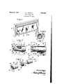
- Fig. 1 is a perspective View of a shade roller provided with a stop adapted to include a keying device according to the invention, and mounted upon a window casing.
- Fig. 2 is an enlarged vertical longitudinal sectional view through one end of the shade roller showing, as part of such stop, a preferred embodiment of said keying device,
- Fig. 3 is aview similar to Fig.2 but showing the position of theparts when the shade is raised to the intended limit.
- Fig. 4 is a vertical transverse sectional view on the line 4-4: of Fig. 2.
- Fig. 5 is a collective perspective view of the several stop parts.
- the numeral 1O designates a shade roller having a flexible shade l1 windable thereon, the free edge 12 of which shade carries the usual reinforcing strip from which a pull cord 13 depends.
- the roller as is well known, is
- a helical spring 14 which,.when wound up, places the roller under tension for winding the shade from a lowered position to a raised position; a suitable ratchet mechanism (not shown).being provided for locking the shade in a lowered position against winding, and having associated therewith a flat trunnion 15 exrib 18b.
- This keying device 18 is here shaped to include a cylindrical head 19, a shank 20, and
- the device 18 having been found to be applicable, by mere finger pressure on'the top of head 19, to cause the curved and sharp lower rounded edge of terminus 21 topierce the comparatively soft wood commonly found as the material of which the roller 10 is made.
- the grain of such wood running longitudinally of the roller, the device 18, during this piercing op eration, is arranged at a removal from the position shown in Figs 2 to 5, that is, with the terminus 21 parallelto said grain; and when the shank 20 is completely down in the wood, the device 18is rotated 90 to arrange the terminus 21 at right angles to said grain. This final condition, as illustrated in Figs.
- the slots 19a. of the keying device of the present invention inter-engage with the side walls of a slot 22 cut longitudinally of the cylindrical wall 23 of a sleeve member 24. If a plurality of keying devices are embedded in the roller, such sleeve member may be provided with one more additional slots like the slot 22, for instance, as indicated at- 22 in Fig. 5; but such duplications are deemed unnecessary. This is so, because when a device 18 is arranged with its terminus 21 at an angle to the wood grain as shown, it can-not be withdrawn from the roller; and with member 24 in place on the roller, the device 18 cannot be rotated about its shank axis to disturb,
- the interior wall of the sleeve member is screw threaded as at 25 for threaded engagement with the exterior threads 26 provided on a cap member 27.
- the end wall of the cap member 27 is provided with a cruciform slot 28 affording the equivalent of two intersecting elongated slots through either of which the flat trunnion 15 may be extended in assembling the parts to have the cap member fit over the end of the roller and to arrange the elements as shown in Figs. 2, 3 and at.
- Both the keying device 18 and the sleeve member 24, but not the cap member 27, rotate with the roller 10, with the result that, due to threads 25 and 26, longitudinal sliding movement is imparted to the sleeve member 24 while there is a relative rotation or spiralling movement between members 24 and 27.
- the parts are as shown in Fig. 2 of the drawings; that is, the outer end 24a of the sleeve member 24: is in spaced relation to the shade bracket 16 and'the device 18 is adjacent to the inner end of the slot 22.
- the spring 14 Upon the actuation of the pull cord 13 to release the ratchet mechanism, the spring 14 imparts a winding movement to the roller 10, and during this winding movement. the sleeve member 24 is fed outwardly until the outer end 240 thereof contacts with the bracket 16, thus arresting movement and bringing the roller, gently, to a stop.
- a key member to preclude relative angular movement of the roller and sleeve comprising a head formed with parallel flats in: diametrically opposite sides, a shank signature.
Landscapes
- Engineering & Computer Science (AREA)
- Structural Engineering (AREA)
- Architecture (AREA)
- Civil Engineering (AREA)
- Preliminary Treatment Of Fibers (AREA)
Description
March 29, 1,932. B. E. MESLER SHADE ROLLER STOP Filed March 28, 1930 ATTORNEY Patented Mar. 29, 1932 .j
" BERTRAM E. MESLER, F BROOKLYN, NEWY'OIR-IK SHADE ROLLER .STOP
Application filed March 28, 1930. Serial No. 439,757..
This invention relates, primarily, to improvements in shade roller stops; and the principal object, in that connection, is to provide a novel keying device, for quick and easy attachment to and anchorage on a wooden shade roller to which the shade roller stop is applied, and also for simplifying the construction and cheapeningthe cost of a shade roller stop of the general type disclosed in U. S. Patent to me No. 1,765,170.
In the accompanying drawings, wherein there are illustratively shown an embodiment of said keying device as at present preferred, and a shade roller stop pursuant to said copending application but of a modified .con-
I struction for co-acting pursuant to present preference with the keying device just men-- tioned:
Fig. 1 is a perspective View of a shade roller provided with a stop adapted to include a keying device according to the invention, and mounted upon a window casing.
Fig. 2 is an enlarged vertical longitudinal sectional view through one end of the shade roller showing, as part of such stop, a preferred embodiment of said keying device,
with the stop parts shown in lowered shade position.
Fig. 3 is aview similar to Fig.2 but showing the position of theparts when the shade is raised to the intended limit.
Fig. 4 is a vertical transverse sectional view on the line 4-4: of Fig. 2.
Fig. 5 is a collective perspective view of the several stop parts.
It is preliminarily pointed out that, in Figs. 1 and 2, as in my said patent, the numeral 1O designates a shade roller having a flexible shade l1 windable thereon, the free edge 12 of which shade carries the usual reinforcing strip from which a pull cord 13 depends. The roller, as is well known, is
hollow for the purpose of housing a helical spring 14, which,.when wound up, places the roller under tension for winding the shade from a lowered position to a raised position; a suitable ratchet mechanism (not shown).being provided for locking the shade in a lowered position against winding, and having associated therewith a flat trunnion 15 exrib 18b.-
tending from one end of the roller 10 to fit into a holding slot in a supporting bracket 16 fixedly secured to. one of the sides of the window casing 17. I
Referring now to the keying device of the present invention, the same is illustrated in Figs. 2 to 5, as embodying aunitary metal fitment fixed to the shade roller 10 adjacent the end supported in the bracket 16. v
This keying device 18, is here shaped to include a cylindrical head 19, a shank 20, and
a blade-like lower terminus 21; thedevice 18 having been found to be applicable, by mere finger pressure on'the top of head 19, to cause the curved and sharp lower rounded edge of terminus 21 topierce the comparatively soft wood commonly found as the material of which the roller 10 is made. The grain of such wood running longitudinally of the roller, the device 18, during this piercing op eration, is arranged at a removal from the position shown in Figs 2 to 5, that is, with the terminus 21 parallelto said grain; and when the shank 20 is completely down in the wood, the device 18is rotated 90 to arrange the terminus 21 at right angles to said grain. This final condition, as illustrated in Figs. 2 and 4, shows the upper blunt edges of the terminus21 locked against the inner surface of the hollow in the roller containing spring 14; an ideal condition. In any event, however, when the device '18 is applied to a wooden roller as above, the terminus 21 will extend at an angle to the grain of such wood, thus to lock the device against withdrawal; whether. or not the shank 20 only, or both said shank and the terminus, be finally embedded in the wood.
Head 19 of this. keying device 18 is slotted on opposite sides as clearly shown in Figs. 2 to 5, such slots being marked 1964; thereby providing above and below each such slot a Referring nowfinally to the other parts of the stop illustrated. whichare identical with or substantial equivalents 01": parts claimed as stop elements: in said copending application, these parts maybe briefly described, as 1 follows: I
The slots 19a. of the keying device of the present invention inter-engage with the side walls of a slot 22 cut longitudinally of the cylindrical wall 23 of a sleeve member 24. If a plurality of keying devices are embedded in the roller, such sleeve member may be provided with one more additional slots like the slot 22, for instance, as indicated at- 22 in Fig. 5; but such duplications are deemed unnecessary. This is so, because when a device 18 is arranged with its terminus 21 at an angle to the wood grain as shown, it can-not be withdrawn from the roller; and with member 24 in place on the roller, the device 18 cannot be rotated about its shank axis to disturb,
said angle.
The interior wall of the sleeve member is screw threaded as at 25 for threaded engagement with the exterior threads 26 provided on a cap member 27. The end wall of the cap member 27 is provided with a cruciform slot 28 affording the equivalent of two intersecting elongated slots through either of which the flat trunnion 15 may be extended in assembling the parts to have the cap member fit over the end of the roller and to arrange the elements as shown in Figs. 2, 3 and at. Both the keying device 18 and the sleeve member 24, but not the cap member 27, rotate with the roller 10, with the result that, due to threads 25 and 26, longitudinal sliding movement is imparted to the sleeve member 24 while there is a relative rotation or spiralling movement between members 24 and 27. Assuming, that the shade is in lowered position, the parts are as shown in Fig. 2 of the drawings; that is, the outer end 24a of the sleeve member 24: is in spaced relation to the shade bracket 16 and'the device 18 is adjacent to the inner end of the slot 22. Upon the actuation of the pull cord 13 to release the ratchet mechanism, the spring 14 imparts a winding movement to the roller 10, and during this winding movement. the sleeve member 24 is fed outwardly until the outer end 240 thereof contacts with the bracket 16, thus arresting movement and bringing the roller, gently, to a stop.
While I have described what I deem to be the most desirable embodiment of my inven tion, it is obvious that other embodiments are possible, and other uses of such embodiments, without in any way departing from the spirit of my invention, and I therefore do not limit myself to the exact details of construction herein set forth nor to anything less than the whole of my invention limited only by the appended claim.
I claim:
In combination with a shade roller and an axially movable sleeve constituting a limiting stop for the roller after a prescribed number of revolutions, the sleeve having a slot opening at one end, a key member to preclude relative angular movement of the roller and sleeve comprising a head formed with parallel flats in: diametrically opposite sides, a shank signature.
- BERTRAM E. MESLER.
Priority Applications (1)
| Application Number | Priority Date | Filing Date | Title |
|---|---|---|---|
| US439757A US1851366A (en) | 1930-03-28 | 1930-03-28 | Shade roller stop |
Applications Claiming Priority (1)
| Application Number | Priority Date | Filing Date | Title |
|---|---|---|---|
| US439757A US1851366A (en) | 1930-03-28 | 1930-03-28 | Shade roller stop |
Publications (1)
| Publication Number | Publication Date |
|---|---|
| US1851366A true US1851366A (en) | 1932-03-29 |
Family
ID=23746016
Family Applications (1)
| Application Number | Title | Priority Date | Filing Date |
|---|---|---|---|
| US439757A Expired - Lifetime US1851366A (en) | 1930-03-28 | 1930-03-28 | Shade roller stop |
Country Status (1)
| Country | Link |
|---|---|
| US (1) | US1851366A (en) |
-
1930
- 1930-03-28 US US439757A patent/US1851366A/en not_active Expired - Lifetime
Similar Documents
| Publication | Publication Date | Title |
|---|---|---|
| US3763916A (en) | Window shade motor | |
| US2632605A (en) | Toilet paper roll holder | |
| DE2016717C3 (en) | Device for attaching a hollow ball or the like. on a leash | |
| US1100252A (en) | Nail or driven fastening. | |
| US1851366A (en) | Shade roller stop | |
| US1668695A (en) | Holder for spinning tops | |
| US873438A (en) | Spring shade-roller. | |
| US1477159A (en) | Window shade | |
| US2003755A (en) | Seal | |
| US1217261A (en) | Guide for window-shades. | |
| US1580798A (en) | Window lock | |
| US601715A (en) | Window-screen | |
| US2033098A (en) | Bottle opener | |
| US1019653A (en) | Window-shade roller. | |
| US2050507A (en) | Device for supporting shade and drapery poles | |
| US2125805A (en) | Spout for sealed metal containers | |
| US1775059A (en) | Wire stretcher | |
| US1653196A (en) | Automobile awning | |
| US2072525A (en) | Apparatus for holding a door open | |
| US880047A (en) | Cane. | |
| US1147834A (en) | Curtain-roller. | |
| US121342A (en) | Improvement in curtain-fixtures | |
| US1773541A (en) | Thread holder for the threading guides of stocking machines | |
| US675110A (en) | Shade-roller. | |
| US1314221A (en) | Disappearing window-scbeen |