US1851358A - Two-way electric switch - Google Patents
Two-way electric switch Download PDFInfo
- Publication number
- US1851358A US1851358A US352385A US35238529A US1851358A US 1851358 A US1851358 A US 1851358A US 352385 A US352385 A US 352385A US 35238529 A US35238529 A US 35238529A US 1851358 A US1851358 A US 1851358A
- Authority
- US
- United States
- Prior art keywords
- disc
- pin
- panel
- movement
- switch
- Prior art date
- Legal status (The legal status is an assumption and is not a legal conclusion. Google has not performed a legal analysis and makes no representation as to the accuracy of the status listed.)
- Expired - Lifetime
Links
- 230000007935 neutral effect Effects 0.000 description 15
- 238000010276 construction Methods 0.000 description 3
- 230000002093 peripheral effect Effects 0.000 description 2
- 230000000979 retarding effect Effects 0.000 description 2
- 230000000994 depressogenic effect Effects 0.000 description 1
- 239000012774 insulation material Substances 0.000 description 1
Images
Classifications
-
- B—PERFORMING OPERATIONS; TRANSPORTING
- B60—VEHICLES IN GENERAL
- B60R—VEHICLES, VEHICLE FITTINGS, OR VEHICLE PARTS, NOT OTHERWISE PROVIDED FOR
- B60R16/00—Electric or fluid circuits specially adapted for vehicles and not otherwise provided for; Arrangement of elements of electric or fluid circuits specially adapted for vehicles and not otherwise provided for
- B60R16/005—Electro-mechanical devices, e.g. switched
Definitions
- This invention relates to electric switches, Referring now more particularly to the and particularly to one to be used in conneccharacters of reference on the drawings, the tion with an illuminated type of automobile numeral 1 denotes the back supporting panel direction signal, such as that shown in my of the switch on which adjacent the top a disc Patent No. 1,686,086 dated October 2nd, 1928. 2 of insulation material is turnably mounted.
- contact strips are associated with 15 fails to perform at the time the need for the binding posts 5 on the back of the panel, by signal has passed.
- the contact 4 may be con-
- the principal object of my present invennected by a wire 6 to a battery 7; and the con tion is to provide a switch for the purpose so tacts M by separate wires 8 to the individual constructed that this double operation is lamps 9 of the signal device.
- the contact avoided and the switch when once closed will strips are of such length and are so disposed remain closed for a predetermined length of relative to the fingers that when one of the time and will then be automatically opened.
- a further object of the invention is to prolength, the other fingers will be disengaged vide a switch of the two-way type, so as to from the contacts la; and when the disc is h selectively control the closing of the circuits turned a certain amountin either direction, to the two lamps of the signal device, in said one finger will remain engaged with the which the automatic circuit holding and battery contact 4 and one only of the other breaking feature is arranged to act equally fingers will then be engaged with the correwell with the use of only one movable switch sponding one 'of the other contacts to.
- a further object of the invention is to proclose a circuit through either one or the other quat a simple and inexpensive device and yet of the signal lights. one which will be exceedingly effective for The disc is thus moved from its neutral po- 5 the purpose for which it is designed. sition to either circuit closing position and
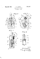
- FIG. 1 is a face view of my improved switch slidable in the cylinder, having a stem 13 shown in its neutral or open position. which at its outer end 'is pivoted. on the plate 45
- Fig. 2 is a similar view showing the switch 1%; a spring 15 about the stem and cylinder arm moved to close one circuit. acting to force the piston to the top of the Fig. 3 is a vertical transverse section of the cylinder. switch.
- Fig. 4 is a sectional elevation of a dashpot distances on both sides of a line between the 1 l or retarding unit detached. pm 10 and the disc axis, and arranged in a position the cylinder and piston s em are axially alined with pin and the disc. Another pin 19 mounted in the plate 1a and projecting toward the panel then fully engages a radial notch 20 cut in the periphery of the disc 2. YWhen the parts are thus positionedone. of the fingers engages the contact a centrally of its length and both light circuits are open.
- the plate 14 also has another pin 21projecting therefrom toward the panel and disposed on a li ie with and between the pins 19 and 10.. I This pin is adaptedto-engage eiher side of a track block 22 mounted on the panel'and whose sides are concentric with the opposite pins 16. This pin 21 is disposed at the apex or top junction of the track surfaces when the plate is in the above stated neutral or switch opening position.
- the piston is provided with a common form ofself-closing valve 23'therein which is arranged to open upon the depression of the piston in the cylinder and to close with the upward movement of the piston.
- a common form ofself-closing valve 23' therein which is arranged to open upon the depression of the piston in the cylinder and to close with the upward movement of the piston.
- a handle lever 26 is formed with and projects from the plate 14 to a point beyond the top of the panel so that the plate maybe easily swung or reciprocated: from one side to the other; the parts on the panel being preferably enclosed by'a cover 27 slotted to permit of the handle projectingtherethrough and having the necessary range of reciprocating movement.
- An electric switch including a plurality of fixed contacts. a contact-finger unit turnable about a fixed axis in opposite directions from a'neutral position to engage'separate ones of the fixed contacts in bridging rela-. tionship, said unit having a peripheral notch, an actuating member mounted for reciprocating movement about an axis. parallel to but spaced from that of the unit, a pin projecting from said member betweensaid axes swinging plate its and arranged to engage the notch when said member and unit are in a neutral position whereby turning movement of said member in either direction from said neutral position will turn the unit until the pin leaves the notch, means acting automatically to return said member to its neutral position, and dashpot means associated with said member to retard such return movement thereof.
- An electric switch comprising a panel, a disc turnably mounted thereon, fixed contacts on the panel grouped in spaced relation about the disc, contact fingers on the disc to bridge diflerent contacts when the disc is turned in either direction from a neutral position, a member separate from the disc mounted on the panel for reciprocating movement in a plane parallel to the disc, the latter having a peripheral notch therein, a pin projecting from the member and engaging the notch when said member and disc are in a neutral position, and during only a short arcuate extent of movement of the member in either direction from such position, spring means acting to return the member to said position, and dashpot means between said member and the panel acting to resist the spring.
- An electric switch comprising a panel. a disc turnably mounted thereon, fixed contacts on the panel grouped in spaced relation about the disc, contact fingers on the disc to bridge different contacts when the disc is turned in either direction from a neutral position, a member separate from the disc mounted on the panel for reciprocating movement in a plane parallel to the disc. and through a cer' tain arc in either direction from a neutral position, means between said member and the disc for causing the latter to be rotated to a contact bridging position with only a relatively short arcuate movement of the member in one direction or the other, means acting to return said member to its neutral position, and means acting to retard such return movement.
- An electric switch including a pair of fixed contacts, a contact-finger unit turnable from a certain position to then engage the contacts in bridging relation, an actuating member movable a certain distance from a neutral position, means between said member and the unit for moving the latter to or from its contact bridging position with a relatively short portion of the total possible movement of said member and for then leaving said unit stationary during any further movement of said member, means acting to return said member to its neutral position, and means acting to retard such return movement.
Landscapes
- Engineering & Computer Science (AREA)
- Mechanical Engineering (AREA)
- Push-Button Switches (AREA)
Description
March 29, 1932. HARRIS 1,851,358
TWO-WAY ELECTRIC SWITCH Filed April 4, 1929 INVENTOR FL. Harris BY 52.&. m
ATTO R N EY Patented Mar. 29, 1932 UNITED STATES PATENT FRANK L. HARRIS, F STOCKTON, CALIFORNIA.
TWO-WAY ELECTRIC SWITCH Application filed April 4, 1929. Serial No. 352,385.
This invention relates to electric switches, Referring now more particularly to the and particularly to one to be used in conneccharacters of reference on the drawings, the tion with an illuminated type of automobile numeral 1 denotes the back supporting panel direction signal, such as that shown in my of the switch on which adjacent the top a disc Patent No. 1,686,086 dated October 2nd, 1928. 2 of insulation material is turnably mounted.
In giving such signals it is essential or at Projecting radially from the disc in spaced least highly desirable that the sign be given relation to each other at the periphery, but continuously for a certain length of time beunitarily connected to each other, within the fore the turn is actually made. With a body portion of the disc, are three spring conl0 switch or ordinary construction this can only tact lingers 3. These fingers are adapted to be done by manually closing the switch and separately engage separated contact strips 4 similarly opening the same. This requires and eta mounted in the panel in insulated retwo distinct operations on the part of the lation to each other and concentric with the driver, the latter one of which he frequently disc. These contact strips are associated with 15 fails to perform at the time the need for the binding posts 5 on the back of the panel, by signal has passed. means of which the contact 4 may be con- The principal object of my present invennected by a wire 6 to a battery 7; and the con tion is to provide a switch for the purpose so tacts M by separate wires 8 to the individual constructed that this double operation is lamps 9 of the signal device. The contact avoided and the switch when once closed will strips are of such length and are so disposed remain closed for a predetermined length of relative to the fingers that when one of the time and will then be automatically opened. fingers engages the contact l centrally of its A further object of the invention is to prolength, the other fingers will be disengaged vide a switch of the two-way type, so as to from the contacts la; and when the disc is h selectively control the closing of the circuits turned a certain amountin either direction, to the two lamps of the signal device, in said one finger will remain engaged with the which the automatic circuit holding and battery contact 4 and one only of the other breaking feature is arranged to act equally fingers will then be engaged with the correwell with the use of only one movable switch sponding one 'of the other contacts to. In
arm, whether the latter is moved to one cirthis manner it will be obvious that the fingers cuit closing position or the other. selectively bridge cooperating contacts to A further object of the invention is to proclose a circuit through either one or the other duce a simple and inexpensive device and yet of the signal lights. one which will be exceedingly effective for The disc is thus moved from its neutral po- 5 the purpose for which it is designed. sition to either circuit closing position and These objects I accomplish by means of maintained in such position for a predetersuch structure and relative arrangement of mined length of time by the following actuparts as will fully appear by a perusal of ating means: the following specification and claims. Fixed in the panel adjacent its lower end 40 In the drawings similar characters of refand vertically alined with the axis of the disc erence indicate corresponding parts in the is a pin 10 on which a cylinder 11 is turnably several views: mounted at its base. A hollow piston 12 is Fig. 1 is a face view of my improved switch slidable in the cylinder, having a stem 13 shown in its neutral or open position. which at its outer end 'is pivoted. on the plate 45 Fig. 2 is a similar view showing the switch 1%; a spring 15 about the stem and cylinder arm moved to close one circuit. acting to force the piston to the top of the Fig. 3 is a vertical transverse section of the cylinder. switch. Transversely spaced pins 16 spaced equal 50 Fig. 4 is a sectional elevation of a dashpot distances on both sides of a line between the 1 l or retarding unit detached. pm 10 and the disc axis, and arranged in a position the cylinder and piston s em are axially alined with pin and the disc. Another pin 19 mounted in the plate 1a and projecting toward the panel then fully engages a radial notch 20 cut in the periphery of the disc 2. YWhen the parts are thus positionedone. of the fingers engages the contact a centrally of its length and both light circuits are open. The plate 14: also has another pin 21projecting therefrom toward the panel and disposed on a li ie with and between the pins 19 and 10.. I This pin is adaptedto-engage eiher side of a track block 22 mounted on the panel'and whose sides are concentric with the opposite pins 16. This pin 21 is disposed at the apex or top junction of the track surfaces when the plate is in the above stated neutral or switch opening position.
r The piston is provided with a common form ofself-closing valve 23'therein which is arranged to open upon the depression of the piston in the cylinder and to close with the upward movement of the piston. When the valve thus opens the air in thecylinder can quickly escape past the valve and through openings 24-. in the piston above the valve or through the piston stem if the latter is hollow. When the valve is closed however air can only enter the cylinder through a small bleed "oassage 25 disposed in the bottom portion of th piston to-one side of the valve. 1 1 I l A handle lever 26 is formed with and projects from the plate 14 to a point beyond the top of the panel so that the plate maybe easily swung or reciprocated: from one side to the other; the parts on the panel being preferably enclosed by'a cover 27 slotted to permit of the handle projectingtherethrough and having the necessary range of reciprocating movement. v
In operation with the swinging of the plate to one side the pin 16 on the opposite side be- 7 comes the pivot of swinging movement of the plate, the engagement of the pin 21 with the track maintaining said pivot pin at thebottom of its slot 17, while permitting the other pin to relatively advance along its slot. With the initial swinging movement of the plate through a relatively short are the pin 19 moves outof the notch 20, turning the disc somewhat in the same manner as is the case with the well known Geneva movement. The depth of the notch is proportioned so that such movement'of the disc is-sufiicient to cause the finger 3 on the same side as that to which theplate is swung to engage the correspondthe axial line between the considerable distance to one ining contact 4a and close the circuit through the corresponding signal lamp.
The spring pressure of the signals against the contact strips holds the disc in the position to which it has been thus moved while the plate 14 is swung still further to one side or until the relatively moving pin 16 engages the top of its slot 17; With this position of the parts the piston is fully depressed in the cylinder, since the stem of the pin is then a side of the temporary pivot oi the plate and substantially on the'sam'e level as said pivot. The pressure onthe handle may then be released and since the valve 23 is thenfclosed a tendency to vacuum is obtained in the cylinder whichacts against the spring action, and which can only be relieved by the entrance of air into the cylinder. Since this can only take place very slowly through the bleed passage, 25 the return movement of the piston and plate to their normal or neutral positions is correspondinglyslow. It will therefore be seen that until the pin 19 again enters the notch 20 and retracts the disc to its normal. position the switch will remain closed and the signal will be continuously actuated. This operationtakes place whether the lever is turned 7 in one directionor the other, since all parts are symmetrically disposed relative to tne normal plane of setting of the actuating plate. r V
It isto be understood that the important feature of my invention lies in "he construction and arrangement of the and -its retarding control mechanism; and that whilel have shown and'described a certain specific typeof contact means actuated V by the movement of the plate, such contact means may be in a. number of difierent forms while still employing the same swinging plate and its peculiar mounting and movements.
From the foregoing description it will be readily seen that I have produced such a device as substantially fulfills the objects of the invention as set forth herein.
While this specification sets forth in detailthe present and preferred construction of the device, still in practice such deviations from such detail maybe resorted to as do not form a departure'trom the spirit of the invention, as defined bv the appended claims.
Having thus described my invention what I claim as new and useful and desire to secure-by Letters Patent is:
1. An electric switch including a plurality of fixed contacts. a contact-finger unit turnable about a fixed axis in opposite directions from a'neutral position to engage'separate ones of the fixed contacts in bridging rela-. tionship, said unit having a peripheral notch, an actuating member mounted for reciprocating movement about an axis. parallel to but spaced from that of the unit, a pin projecting from said member betweensaid axes swinging plate its and arranged to engage the notch when said member and unit are in a neutral position whereby turning movement of said member in either direction from said neutral position will turn the unit until the pin leaves the notch, means acting automatically to return said member to its neutral position, and dashpot means associated with said member to retard such return movement thereof.
2. An electric switch comprising a panel, a disc turnably mounted thereon, fixed contacts on the panel grouped in spaced relation about the disc, contact fingers on the disc to bridge diflerent contacts when the disc is turned in either direction from a neutral position, a member separate from the disc mounted on the panel for reciprocating movement in a plane parallel to the disc, the latter having a peripheral notch therein, a pin projecting from the member and engaging the notch when said member and disc are in a neutral position, and during only a short arcuate extent of movement of the member in either direction from such position, spring means acting to return the member to said position, and dashpot means between said member and the panel acting to resist the spring.
3. An electric switch comprising a panel. a disc turnably mounted thereon, fixed contacts on the panel grouped in spaced relation about the disc, contact fingers on the disc to bridge different contacts when the disc is turned in either direction from a neutral position, a member separate from the disc mounted on the panel for reciprocating movement in a plane parallel to the disc. and through a cer' tain arc in either direction from a neutral position, means between said member and the disc for causing the latter to be rotated to a contact bridging position with only a relatively short arcuate movement of the member in one direction or the other, means acting to return said member to its neutral position, and means acting to retard such return movement.
4:. An electric switch including a pair of fixed contacts, a contact-finger unit turnable from a certain position to then engage the contacts in bridging relation, an actuating member movable a certain distance from a neutral position, means between said member and the unit for moving the latter to or from its contact bridging position with a relatively short portion of the total possible movement of said member and for then leaving said unit stationary during any further movement of said member, means acting to return said member to its neutral position, and means acting to retard such return movement.
In testimony whereof I aiiix my signature.
FRANK L. HARRIS.
Priority Applications (1)
| Application Number | Priority Date | Filing Date | Title |
|---|---|---|---|
| US352385A US1851358A (en) | 1929-04-04 | 1929-04-04 | Two-way electric switch |
Applications Claiming Priority (1)
| Application Number | Priority Date | Filing Date | Title |
|---|---|---|---|
| US352385A US1851358A (en) | 1929-04-04 | 1929-04-04 | Two-way electric switch |
Publications (1)
| Publication Number | Publication Date |
|---|---|
| US1851358A true US1851358A (en) | 1932-03-29 |
Family
ID=23384917
Family Applications (1)
| Application Number | Title | Priority Date | Filing Date |
|---|---|---|---|
| US352385A Expired - Lifetime US1851358A (en) | 1929-04-04 | 1929-04-04 | Two-way electric switch |
Country Status (1)
| Country | Link |
|---|---|
| US (1) | US1851358A (en) |
-
1929
- 1929-04-04 US US352385A patent/US1851358A/en not_active Expired - Lifetime
Similar Documents
| Publication | Publication Date | Title |
|---|---|---|
| US1645487A (en) | Combination light | |
| US2494015A (en) | Permutation electric switch | |
| US1851358A (en) | Two-way electric switch | |
| ES159008U (en) | Electric switch. (Machine-translation by Google Translate, not legally binding) | |
| US2059023A (en) | Controller | |
| US3200657A (en) | Electric switch | |
| US1608610A (en) | Electric switch | |
| US1930435A (en) | Mercury switch | |
| US2149226A (en) | Control switch | |
| US1653517A (en) | Controlling switch | |
| US1835014A (en) | Knock-out switch | |
| US2629029A (en) | Electric lock structure | |
| US2882373A (en) | Switch operating device | |
| US2604555A (en) | Auto headlight switching apparatus | |
| US635373A (en) | Electric switch. | |
| US1811261A (en) | Alarm time switch | |
| US1492384A (en) | Switch mechanism | |
| US1533513A (en) | Signaling apparatus for railroad crossings | |
| US2227337A (en) | Control mechanism for elevator cars | |
| DE386962C (en) | Lighting device for cash registers | |
| US1446780A (en) | Electric flashing device | |
| US1395579A (en) | Resistance-switch | |
| US2816182A (en) | Switch | |
| US1832286A (en) | Snap switch | |
| US1950312A (en) | Device for controlling the illumination of lamps |