US1851355A - Electric doorlock - Google Patents
Electric doorlock Download PDFInfo
- Publication number
- US1851355A US1851355A US50916731A US1851355A US 1851355 A US1851355 A US 1851355A US 50916731 A US50916731 A US 50916731A US 1851355 A US1851355 A US 1851355A
- Authority
- US
- United States
- Prior art keywords
- lock
- wheel
- door
- housing
- arm
- Prior art date
- Legal status (The legal status is an assumption and is not a legal conclusion. Google has not performed a legal analysis and makes no representation as to the accuracy of the status listed.)
- Expired - Lifetime
Links
Images

Classifications
-
- E—FIXED CONSTRUCTIONS
- E05—LOCKS; KEYS; WINDOW OR DOOR FITTINGS; SAFES
- E05B—LOCKS; ACCESSORIES THEREFOR; HANDCUFFS
- E05B47/00—Operating or controlling locks or other fastening devices by electric or magnetic means
-
- Y—GENERAL TAGGING OF NEW TECHNOLOGICAL DEVELOPMENTS; GENERAL TAGGING OF CROSS-SECTIONAL TECHNOLOGIES SPANNING OVER SEVERAL SECTIONS OF THE IPC; TECHNICAL SUBJECTS COVERED BY FORMER USPC CROSS-REFERENCE ART COLLECTIONS [XRACs] AND DIGESTS
- Y10—TECHNICAL SUBJECTS COVERED BY FORMER USPC
- Y10T—TECHNICAL SUBJECTS COVERED BY FORMER US CLASSIFICATION
- Y10T70/00—Locks
- Y10T70/70—Operating mechanism
- Y10T70/7051—Using a powered device [e.g., motor]
- Y10T70/7062—Electrical type [e.g., solenoid]
- Y10T70/7119—Projected electrically only
Definitions
- This invention relates to electric door locks.
- the main object of'the invention is to provide an electrically operated lock which may be operated to lock a door from any one of several remote pointsythe lock being thus particularly adaptable for use in banks or business institutions to prevent the entrance of robbers or the like or to lock the same within the building-after they have entered until the arrival of oflicers of the law.
- Another object is to rovide an electric door lock particularly ad pted for-use upon revolving doors of any type or form. Another object is to provide an electric door lock which may be instantly operated to either lock or unlock a door by a momentary closing of any one of several remotely located switches.
- a further object is to provide a lock of the above character in a simple, durable and efficient form and one which may be readily installed.
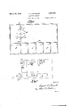
- Figure ,1 illustrates a floor plan of a bank or similar building as equipped with the lock.
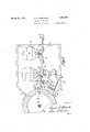
- FIG. 2 is an enlarged-plan view of the lock housing and locking elements.
- Figure 3 is a section along the line 3-3 in Figure Figure 4 is a detail side view of the trio tion roller and its carrier or mounting.
- Figure 5 is a detail side view of the alarm switch.
- Figure 6 is a detail in perspective of the alarmswitch operating arm.
- Figure 7 is a diagrammatic wiring plan of the lock operating elements and control switches.
- my invention is shown in use upon a conventional revolving door A as mounted in the doorwav B of the partition. C in the building D.
- the building D for use as a bank includes the front information or ofiice booth E and the teller cages F, the former being located forwardly of the partition C and the latter rearwardly thereof iasn Serial in. 509,167.
- tubular vertical post 1 carrying the door A is pro vided at its lower end with a lock wheel- 2 which has a plurality of teeth 3 formed around its upper margin.
- a lock housing 4 is mounted adjacent the, wheel 2 and is open 7 at one end 5 whereby the said wheel may project somewhat within the housing as shown.
- This housing 4 may be set in the floor of the buildingflD or maybe located in any 5 other position either above or below the door A by varying the length of the shaft 1 and the position of the lock wheel 2 to suit.
- a stand or hearing 6 is mounted within the 1 housing 4 adjacent the periphery of the lock 7 wheel'2 and the same includes the spaced vertical sides '7 providing a cleft therebetween in which a lock bar 8 is fulcrumed in termediate its ends by means of the bolt 9 passed through said sides 7.
- This lock bar 8 extends at its forward end 10 over the toothed margin of the wheel 2 and the bolt 9 is so located that this end of the bolt of its own weight normally falls or swings downwardly.
- the forward end 10 of the lock bar is so shaped that it may fit downward between any adjacent ones of the teeth 3 of the locking wheel 2 thus normally locking the wheel 2 and consequently the revolving door Aagainst rotation.
- a lock bar trip le- 35 ver 11 is hinged at its lower end at 12 to the base 13 of the lock housing 4 at the rear. of the bearing 6 and is provided at its upper end with an angularly bent hook 14.
- a pin 19 is mounted eccentrically on the disk 18 and the arrangement and location of the motor 16and disk 18 are such that this pin 19 projects outward into the path of the trip tween the trip leverandbearing as also shown in Figure 3. Itwill now be understood that should the motor 16 be started the pin 19 will be carried around on the disk 18 and will strike the trip lever 11 swinging the same rearward or downward so that the hook 8 14 is. disengaged from'the lug 15 allowing the forward end of the lock bar 8 to drop.
- a release arm 31 is fulcrumed at 32 on the bolt 9 to one side of the bearing 6 and has its forward end. 33 bent laterally across beneath the forward end 10 of the lock bar 8. Rearwardly ofthe fulcrum 32 the arm 31 is extended 'for some distance rearwardly of the trip lever 11 and is pref- 'erahly though not necessarily twisted through an arc of 90 degrees .as shown at 34. weight 35 in the form of a length of material similar to the arm 31 is secured .to
- I 35 the underside of the rear portion thereof and terminates in a downwardly extended stop 36 at some distance from the rear end of the arm as shown.
- a released lever-37 is hinged by its lower end at 38 to the base 13 of the.
- the laterally bent end 33 of the release arm rests aga nst the underside of the forward end 10 of the lock bar 8 when the same is in its lowered or locking position.
- the. forward end of the lock bar 8 may be raised out of engagement with the teeth 3 by swinging the release lever 37 out from beneath the rear end of the release arm 31, the weight 35 together with the eccentric location of the fulcrum 32 causing the rear end of the release 'arm to swing downward and overcome the weight of the lock bar.
- a motor 39 similar to the motor 16 is provided and the same is located adjacent the rear end of the arm 31.
- This motor 39 carries a disk 40 and an eccentrically located pin 41 thereon which ope'rates toswing the lever 37 rearward when the motor is started in identically 5 the manner described hereinbefore with reference to the trip lever 11.
- the elements just described constitute the unlocking mechamsm.
- the motors 16 and 39 may be controlled by suitabl located and arranged wiring and switches, one arrangement being shown in Figure 7 for use in connection with the building arrangement illustrated in Figure 1."
- An unlocking switch 44 is mounted in the information or office booth E and is connected between the remaining wire 42a and the remaining contact of the motor 39 whereby the said motor may be started by closing the said switch 44.
- the door A may e instantly locked by closing any of the switches 43 and may then be unlocked when desired by closing the switch 44.
- Arcuate guards 7 O are placed'at each side of the doorway B to prevent passage therethrough no matter in what position the door A is looked as will be understood.
- the door A may be left unlocked at night and so arranged that a slightmovement will the means now to be des'cribed.
- a support bar or carrier 45 is fulcrumed intermediate its ends at 46to a pin 47 set in the base 13 of thehousing 4 adjacent the margin of'the lock wheel 2.
- a retractile coil ⁇ spring 48 is stretched between one end of the carrier 45 and a screw 49 secured to the housing base 13 and this spring normally forces 'the opposite end ,50 of the carrier toward the wheel 2.
- a friction wheel 51 is journaled on a pin .52 vertically set in the carrier 45 between its fulcrum 46 and the end 50 and the pin and friction wheel are steadied by the bracket 53 arranged as shown.
- the friction wheel 51 is reduced near its upper end providing a shoulder 54-for a purpose to be described.
- the action of the sprin 48 serves to normally hold the friction w eel in contact with the periphery of the lock wheel 2 whereby the former will be rotated by the latter as the door. A revolves in use as will be understood.
- a single pole, single throw knife switch 20 is mounted on-theside of a post 21 secured to the base 13 0f the lock housing 4 at some distance across the same from the motor 16 and a switch operating arm 22 is fulcrumed at 23 to 'a-block 24 located between the said motor and the post 21. At one end the arm and at its other end the arm is reduced and formed. into'a finger 26 loosely engaging a slot 27 provided in the switch blade 28.
- a link 55 is pivotally attached at one end 56 to the arm 22 between its fulcrum 2 3 and the switch 20 and is pivoted at its other end at 57 to the shoulder 54 formed by reducing of the friction wheel 51 as described.
- the wire 59 passed through an aperture 64 in the 'rear end 61 of the housing 4 and has a finger loop 62 for operation and an offset 63 by means of which the friction wheel 51 may be held pulled away from with the lower margin of the aperture 64 as shown.
- a cable (not shown) maybe'substituted for the wire 59f0r, remote control of the friction wheel 51 if desired.
- the friction wheel 51 is left in contact with the lock wheel 1 2 at night or when the locking of the door A by the locking switches 43 is not practical and is normally not used in the daytime dur-
- the switch 20 is conventionally connected as shown in Figure 7 Y to an alarm bell 65 or other alarm disposed in any suitable location and an audible alarm is thus sounded coincident with the locking r of the door A should any 7 intruders attempt to pass therethrough. It willbe evident that the friction wheel 51 normally rests in such position that the switch 20 is open and .the
- the top 66-thereof is provided with a hinged door 67.
- the wires supplying the motors 16 and 39 may be passed through the post 1 as-shown at .68 in Figure 2.
- a toothed lock wheel connected thereto for rotation as the door is operated, a lock housing adjacent to and partially enclosing the lock wheel, a bearing in the lock housing, a lock bar fulcrumed in the bearing one end of the lock bar being adapted to normally engage the teeth on the said lock wheel, a lug on the opposite end of the lock bar, a trip lever hinged at one end to the housing and having a hook at its free end adapted to engage the end lug of the lock bar and hold the opposite end outof engagement with the lock wheel, an electric motor in the lock housing, a disk rotatably mounted on the motor, and a pin eccentrically mounted on the said disk and extended therefrom adjacent the trip lever.
- a lock wheel connected to the door for rotation thereby, the said lock wheel having teeth around the margin of its upper face, a housing adjacent the lock wheel, a bearing in the housing, and a lock bar pivotally and eccentrically mounted in the said bearing and adapted to normally of ,its own weight rest downwardly in engagewheel.
- a lock rest downwardly in wheel connected to the door to revolve there? with, lock teeth formed around the margin" of the upper face of the lock wheel, a housing adjacent the lock wheel, a bearing in the housing, a lock bar eccentrically pivoted in the bearing to normally rest downward at one end 7 the teeth on the lock in engagement with wheel, a hook hinged, to the housing and adapted to engage the lock bar to hold the same elevated out of engagement with the lock wheel, and means operable by the rotation of the door and lock wheel for disengaging said hook from the lock bar.
- a lock wheel connected to the door to revolve there with, lock teeth formed around the margin of the upper face of the lock wheel, a housing adjacent the lock wheel, a bearing in the housing, a' lock bar eccentrically pivoted in the bearing to normally rest downward at one end in engagement with the teeth on the lock wheel, a hook hinged to the housing and adapted to engage the look bar to hold the same elevated out of engagement with the lock wheel, and means operable by the rota tion of the door and lock wheel for disengaging said hook from the lock bar, said'mean's comprising a friction wheel adapted to releasably engage the periphery of the lock wheel, an arm fulcrumed intermediate its ends and projectinglat one end into engagement with the said 00k, and a link eccentrically connected to the friction wheel and arm.
Landscapes
- Power-Operated Mechanisms For Wings (AREA)
Description
March 29, 1932. v k A. H. GOEDECKE 1,851,355
I ELECTRIC DOORLOCKY lfiledJan. 16, 1931 3 sheets-sheet l L 70 4 F4:/ 1 4 7a 7 5 I March 29, 1932. A. H..GOEDECKE 1,851,355 7 ELECTRIC DOORLOCK Filed Jan. 16, 1931 3 Sheets-Sheet 2 March 29, 1932. GQEDECKE 1,851,355
ELECTRIC DOORLOCK Filed Jan. 16, 1931 3 Sheets-Sheet 3 Patented Mar; 29,' 1932 NT OFFICE AUGUST H. GOEDECKE, OF TERRE HATJ'TE, INDIANA.
mam 130031.001:
Application filed January 16,
This invention relates to electric door locks. The main object of'the invention is to provide an electrically operated lock which may be operated to lock a door from any one of several remote pointsythe lock being thus particularly adaptable for use in banks or business institutions to prevent the entrance of robbers or the like or to lock the same within the building-after they have entered until the arrival of oflicers of the law.
Another object is to rovide an electric door lock particularly ad pted for-use upon revolving doors of any type or form. Another object is to provide an electric door lock which may be instantly operated to either lock or unlock a door by a momentary closing of any one of several remotely located switches.
A further object is to provide a lock of the above character in a simple, durable and efficient form and one which may be readily installed.
' With these and other objects in view the invention resides in the novel construction and arrangement of parts as hereinafter set forth and claimed, reference being had to the accompanying drawings, wherein:
Figure ,1 illustrates a floor plan of a bank or similar building as equipped with the lock.
- Figure 2 is an enlarged-plan view of the lock housing and locking elements.
Figure 3 is a section along the line 3-3 in Figure Figure 4 is a detail side view of the trio tion roller and its carrier or mounting.
Figure 5 is a detail side view of the alarm switch.
Figure 6 is a detail in perspective of the alarmswitch operating arm. Figure 7 is a diagrammatic wiring plan of the lock operating elements and control switches.
In the drawings my invention is shown in use upon a conventional revolving door A as mounted in the doorwav B of the partition. C in the building D. The building D for use as a bank includes the front information or ofiice booth E and the teller cages F, the former being located forwardly of the partition C and the latter rearwardly thereof iasn Serial in. 509,167.
whereby the door-A controls the entrance into the banking room proper. This arrangementis only shown for convenience in description and it isv understood that anyv other arrangement may be used as desired.
In accordance with the invention the tubular vertical post 1 carrying the door A is pro vided at its lower end with a lock wheel- 2 which has a plurality of teeth 3 formed around its upper margin. A lock housing 4 is mounted adjacent the, wheel 2 and is open 7 at one end 5 whereby the said wheel may project somewhat within the housing as shown. This housing 4 may be set in the floor of the buildingflD or maybe located in any 5 other position either above or below the door A by varying the length of the shaft 1 and the position of the lock wheel 2 to suit. A stand or hearing 6 is mounted within the 1 housing 4 adjacent the periphery of the lock 7 wheel'2 and the same includes the spaced vertical sides '7 providing a cleft therebetween in which a lock bar 8 is fulcrumed in termediate its ends by means of the bolt 9 passed through said sides 7. This lock bar 8 extends at its forward end 10 over the toothed margin of the wheel 2 and the bolt 9 is so located that this end of the bolt of its own weight normally falls or swings downwardly. The forward end 10 of the lock bar is so shaped that it may fit downward between any adjacent ones of the teeth 3 of the locking wheel 2 thus normally locking the wheel 2 and consequently the revolving door Aagainst rotation. A lock bar trip le- 35 ver 11 is hinged at its lower end at 12 to the base 13 of the lock housing 4 at the rear. of the bearing 6 and is provided at its upper end with an angularly bent hook 14. The
rear endof the lock bar 8 is provided with an angularly and upwardly extended lug or ear15 and. the'hook 14 on the trip lever 11 is adapted to overlierthis lug in the manner shown in Figure 3, the saidlever 11 being of such length that the forward end 10 of the lock bar 8 will be held raised out of engagement with vthe teeth 3 when the said hook and-lug are so engaged. The wheel 2 and door A mayof course turn freely when the lock bar 8 is so held. An electric nptor hou 16 is mounted in the lock housing 4 adjacent the rear end of the lock bar 8 and at right angles thereto, and a small disk 17 is secured to the drive shaft of this motor as shown.
A pin 19 is mounted eccentrically on the disk 18 and the arrangement and location of the motor 16and disk 18 are such that this pin 19 projects outward into the path of the trip tween the trip leverandbearing as also shown in Figure 3. Itwill now be understood that should the motor 16 be started the pin 19 will be carried around on the disk 18 and will strike the trip lever 11 swinging the same rearward or downward so that the hook 8 14 is. disengaged from'the lug 15 allowing the forward end of the lock bar 8 to drop.
The door A may thus be locked against rotation by simply starting the motor 16 as will be understood. A release arm 31 is fulcrumed at 32 on the bolt 9 to one side of the bearing 6 and has its forward end. 33 bent laterally across beneath the forward end 10 of the lock bar 8. Rearwardly ofthe fulcrum 32 the arm 31 is extended 'for some distance rearwardly of the trip lever 11 and is pref- 'erahly though not necessarily twisted through an arc of 90 degrees .as shown at 34. weight 35 in the form of a length of material similar to the arm 31 is secured .to
I 35 the underside of the rear portion thereof and terminates in a downwardly extended stop 36 at some distance from the rear end of the arm as shown. A released lever-37 is hinged by its lower end at 38 to the base 13 of the.
sing 4 beneath the rear end of the released arm 31 and this lever may be swung upward beneath the said rear endof the release arm against the stop36 .whereby the arm is held in. asubstantially'horizontal plane as shown.
In thisposition the laterally bent end 33 of the release arm rests aga nst the underside of the forward end 10 of the lock bar 8 when the same is in its lowered or locking position. Thus it will be understood. that the. forward end of the lock bar 8 may be raised out of engagement with the teeth 3 by swinging the release lever 37 out from beneath the rear end of the release arm 31, the weight 35 together with the eccentric location of the fulcrum 32 causing the rear end of the release 'arm to swing downward and overcome the weight of the lock bar. In order to swing the release lever rearward as descrihed'a motor 39 similar to the motor 16 is provided and the same is located adjacent the rear end of the arm 31. This motor 39 carries a disk 40 and an eccentrically located pin 41 thereon which ope'rates toswing the lever 37 rearward when the motor is started in identically 5 the manner described hereinbefore with reference to the trip lever 11. The elements just described constitute the unlocking mechamsm.
The motors 16 and 39 may be controlled by suitabl located and arranged wiring and switches, one arrangement being shown in Figure 7 for use in connection with the building arrangement illustrated in Figure 1."
16 whereby the said motor may be started I by closing any of the switches 43. An unlocking switch 44 is mounted in the information or office booth E and is connected between the remaining wire 42a and the remaining contact of the motor 39 whereby the said motor may be started by closing the said switch 44.
' From the foregoing it will be apparent that the door A may e instantly locked by closing any of the switches 43 and may then be unlocked when desired by closing the switch 44. Arcuate guards 7 O are placed'at each side of the doorway B to prevent passage therethrough no matter in what position the door A is looked as will be understood.
The door A may be left unlocked at night and so arranged that a slightmovement will the means now to be des'cribed.
' A support bar or carrier 45 is fulcrumed intermediate its ends at 46to a pin 47 set in the base 13 of thehousing 4 adjacent the margin of'the lock wheel 2. A retractile coil {spring 48 is stretched between one end of the carrier 45 and a screw 49 secured to the housing base 13 and this spring normally forces 'the opposite end ,50 of the carrier toward the wheel 2. A friction wheel 51 is journaled on a pin .52 vertically set in the carrier 45 between its fulcrum 46 and the end 50 and the pin and friction wheel are steadied by the bracket 53 arranged as shown. The friction wheel 51 is reduced near its upper end providing a shoulder 54-for a purpose to be described. The action of the sprin 48 serves to normally hold the friction w eel in contact with the periphery of the lock wheel 2 whereby the former will be rotated by the latter as the door. A revolves in use as will be understood.
.A single pole, single throw knife switch 20 is mounted on-theside of a post 21 secured to the base 13 0f the lock housing 4 at some distance across the same from the motor 16 and a switch operating arm 22 is fulcrumed at 23 to 'a-block 24 located between the said motor and the post 21. At one end the arm and at its other end the arm is reduced and formed. into'a finger 26 loosely engaging a slot 27 provided in the switch blade 28. A link 55 is pivotally attached at one end 56 to the arm 22 between its fulcrum 2 3 and the switch 20 and is pivoted at its other end at 57 to the shoulder 54 formed by reducing of the friction wheel 51 as described. It will now be understoodthat with the friction wheel 51 in contact with the lock wheel 2 any rotation of the latter by use of the door A will rotate the friction wheel causing a pull upon the link 55. This in turn will pull the outer end of the arm 22 toward the switch 20 swinging the blade 28 thereof into the switch clip 58 and closing the said switch. At the same time the opposite end of the arm 22 will beswung toward the trip leverll and will contact and swingthe same rearward so that the lock bar 8 is released and drops to its locking position as will be understood and as herelnbefore described. A wire 59 is secured at 60 to the end 50 of the carrier and serves as a means for pulling the friction wheel 51 out of contact with the wheel 2 when desired. The wire 59 passed through an aperture 64 in the 'rear end 61 of the housing 4 and has a finger loop 62 for operation and an offset 63 by means of which the friction wheel 51 may be held pulled away from with the lower margin of the aperture 64 as shown. A cable (not shown) maybe'substituted for the wire 59f0r, remote control of the friction wheel 51 if desired. The friction wheel 51 is left in contact with the lock wheel 1 2 at night or when the locking of the door A by the locking switches 43 is not practical and is normally not used in the daytime dur- The switch 20 is conventionally connected as shown in Figure 7 Y to an alarm bell 65 or other alarm disposed in any suitable location and an audible alarm is thus sounded coincident with the locking r of the door A should any 7 intruders attempt to pass therethrough. It willbe evident that the friction wheel 51 normally rests in such position that the switch 20 is open and .the
mit access to the housing .4 for adjustments or resetting of the lock mechanism the top 66-thereof is provided with a hinged door 67. The wires supplying the motors 16 and 39 may be passed through the post 1 as-shown at .68 in Figure 2.
The operation of the device will be understood from the foregoing and it'will be apparent that I have provided a simple, eflicient \and positive lock for the door both'day and night and one which may be readily adapted ment with the teeth ,on the lock the lock wheel, a bearing a lock bar pivotally and eccentrically mount' combination with a door, a toothed lock wheel operatably connected to the door for rotation thereby as the door is operated, a lock housing adjacent the lock wheel, a bearing therein, and a lock bar fulcrumed in the bearing. and adaptedto engage the teeth on the said lock wheel to lock the same against rotation.
2. In a device of the kind described, in combination with a door, a toothed lock wheel connected thereto for rotation as the door is operated, a lock housing adjacent to and partially enclosing the lock wheel, a bearing in the lock housing, a lock bar fulcrumed in the bearing one end of the lock bar being adapted to normally engage the teeth on the said lock wheel, a lug on the opposite end of the lock bar, a trip lever hinged at one end to the housing and having a hook at its free end adapted to engage the end lug of the lock bar and hold the opposite end outof engagement with the lock wheel, an electric motor in the lock housing, a disk rotatably mounted on the motor, and a pin eccentrically mounted on the said disk and extended therefrom adjacent the trip lever.
3. In a device of the kind described, in combination with a revolving door, a lock wheel connected to the door for rotation thereby, the said lock wheel having teeth around the margin of its upper face, a housing adjacent the lock wheel, a bearing in the housing, and a lock bar pivotally and eccentrically mounted in the said bearing and adapted to normally of ,its own weight rest downwardly in engagewheel.
4. In a device of the-kind described, in combination with a revolving door, a lock wheel connected to the door for rotation thereby, the said lock wheel having teeth around the margin of its upper'face, a housing adjacent in the housing, and
ed in the said bearing and adapted to normally of its own weight engagement with the teeth on the lock wheel, a hook hinged in the housing and adaptedto engage and hold the said lock bar in an ele vated positioni disengaged from the lock wheel.
5. In a device of thekind described, in
combination with a revolving door, a lock rest downwardly in wheel connected to the door to revolve there? with, lock teeth formed around the margin" of the upper face of the lock wheel, a housing adjacent the lock wheel, a bearing in the housing, a lock bar eccentrically pivoted in the bearing to normally rest downward at one end 7 the teeth on the lock in engagement with wheel, a hook hinged, to the housing and adapted to engage the lock bar to hold the same elevated out of engagement with the lock wheel, and means operable by the rotation of the door and lock wheel for disengaging said hook from the lock bar.
6. In a device of the kind described, in combination with a revolving door, a lock wheel connected to the door to revolve there with, lock teeth formed around the margin of the upper face of the lock wheel, a housing adjacent the lock wheel, a bearing in the housing, a' lock bar eccentrically pivoted in the bearing to normally rest downward at one end in engagement with the teeth on the lock wheel, a hook hinged to the housing and adapted to engage the look bar to hold the same elevated out of engagement with the lock wheel, and means operable by the rota tion of the door and lock wheel for disengaging said hook from the lock bar, said'mean's comprising a friction wheel adapted to releasably engage the periphery of the lock wheel, an arm fulcrumed intermediate its ends and projectinglat one end into engagement with the said 00k, and a link eccentrically connected to the friction wheel and arm.
In testimony whereof I afiix my signature.
AUGUST H. GOEDECKE.
Priority Applications (1)
| Application Number | Priority Date | Filing Date | Title |
|---|---|---|---|
| US50916731 US1851355A (en) | 1931-01-16 | 1931-01-16 | Electric doorlock |
Applications Claiming Priority (1)
| Application Number | Priority Date | Filing Date | Title |
|---|---|---|---|
| US50916731 US1851355A (en) | 1931-01-16 | 1931-01-16 | Electric doorlock |
Publications (1)
| Publication Number | Publication Date |
|---|---|
| US1851355A true US1851355A (en) | 1932-03-29 |
Family
ID=24025572
Family Applications (1)
| Application Number | Title | Priority Date | Filing Date |
|---|---|---|---|
| US50916731 Expired - Lifetime US1851355A (en) | 1931-01-16 | 1931-01-16 | Electric doorlock |
Country Status (1)
| Country | Link |
|---|---|
| US (1) | US1851355A (en) |
Cited By (1)
| Publication number | Priority date | Publication date | Assignee | Title |
|---|---|---|---|---|
| US3924546A (en) * | 1972-09-30 | 1975-12-09 | Gisberto Pretini | Anti robbery protection equipment |
-
1931
- 1931-01-16 US US50916731 patent/US1851355A/en not_active Expired - Lifetime
Cited By (1)
| Publication number | Priority date | Publication date | Assignee | Title |
|---|---|---|---|---|
| US3924546A (en) * | 1972-09-30 | 1975-12-09 | Gisberto Pretini | Anti robbery protection equipment |
Similar Documents
| Publication | Publication Date | Title |
|---|---|---|
| US1949283A (en) | Depository | |
| US1759129A (en) | After-hour depository | |
| US1851355A (en) | Electric doorlock | |
| US2169855A (en) | Article collection and delivery box | |
| US1992096A (en) | Robberproof fixture, lock, and alarm for banks and the like | |
| US1954135A (en) | Locking mechanism | |
| US1704865A (en) | After-hour depository | |
| US1434180A (en) | Gate | |
| US1611787A (en) | Bank burglar trap | |
| US1959253A (en) | Window lock and burglar alarm signal | |
| US2171263A (en) | Protective device | |
| US3126081A (en) | Luggage lockers and the like | |
| US1555420A (en) | Door opener and closer | |
| US1350958A (en) | Ginia | |
| US584309A (en) | Apparatus for securing funds of banks against robbery | |
| US1309645A (en) | lopez | |
| US1401959A (en) | Burglar-proof mechanism for banks | |
| US2965210A (en) | Locker with accumulation mechanism | |
| US3286664A (en) | Holdup-proof booth | |
| US1722070A (en) | Time lock | |
| US2659333A (en) | Self-contained burglar alarm unit | |
| US1506791A (en) | Bank-protecting structure | |
| US2378492A (en) | Vault or safe | |
| US2443553A (en) | Burglar alarm | |
| US1698994A (en) | Theft-protection door for buildings |