US1851354A - Short wave adapter - Google Patents
Short wave adapter Download PDFInfo
- Publication number
- US1851354A US1851354A US312623A US31262328A US1851354A US 1851354 A US1851354 A US 1851354A US 312623 A US312623 A US 312623A US 31262328 A US31262328 A US 31262328A US 1851354 A US1851354 A US 1851354A
- Authority
- US
- United States
- Prior art keywords
- panel
- tube
- mounting
- short wave
- condenser
- Prior art date
- Legal status (The legal status is an assumption and is not a legal conclusion. Google has not performed a legal analysis and makes no representation as to the accuracy of the status listed.)
- Expired - Lifetime
Links
- 238000004804 winding Methods 0.000 description 11
- 238000010276 construction Methods 0.000 description 6
- 230000008929 regeneration Effects 0.000 description 5
- 238000011069 regeneration method Methods 0.000 description 5
- 239000004020 conductor Substances 0.000 description 4
- 230000000875 corresponding effect Effects 0.000 description 4
- 101100001670 Emericella variicolor andE gene Proteins 0.000 description 1
- 230000003321 amplification Effects 0.000 description 1
- 230000005540 biological transmission Effects 0.000 description 1
- 230000000052 comparative effect Effects 0.000 description 1
- 230000001276 controlling effect Effects 0.000 description 1
- 230000000694 effects Effects 0.000 description 1
- 230000006870 function Effects 0.000 description 1
- 150000002500 ions Chemical class 0.000 description 1
- 238000004519 manufacturing process Methods 0.000 description 1
- 238000000034 method Methods 0.000 description 1
- 238000003199 nucleic acid amplification method Methods 0.000 description 1
- 230000008707 rearrangement Effects 0.000 description 1
- 230000001172 regenerating effect Effects 0.000 description 1
Images

Classifications
-
- H—ELECTRICITY
- H04—ELECTRIC COMMUNICATION TECHNIQUE
- H04B—TRANSMISSION
- H04B1/00—Details of transmission systems, not covered by a single one of groups H04B3/00 - H04B13/00; Details of transmission systems not characterised by the medium used for transmission
- H04B1/02—Transmitters
- H04B1/03—Constructional details, e.g. casings, housings
- H04B1/034—Portable transmitters
Definitions
- My invention relates to radio receivingapparatus, and more particularly to an auxiliary short Wave receiving apparatus rfor use with the usual broadcast receivingset, Whereby short'wave transmission maybe received and amplified Without unnecessary duplication of parts and apparatus.
- Y Short' wave or high frequency yreception
- the short Wave receiver forming the subject matter hereof, comprises a one tube regenerative circuit fitted lwith a connecting cable enabling it to be Ffplug'gedi,x into a. standardtube socket of an ordinary broadcast receiver from which current will be supplied at the necessary voltages for the opern ation of the short wave apparatus, known as an uadapter.
- the au- Vdio amplifyingcircuits of suchreceiver are xemployed in conjunction With the short wave adapter to afiford a complete short wave .re'- DCverof good-operative'characteristics.
- the short wave adapter By connecting theshort wave adapter into the first radio frequencyx tube socket of aradio frequency amplifying receiver and'allowing the short wave adapter ⁇ tube to oscillatefat a frequency equal to that of the signal desired V plus or minusV the frequency to which the a broadcast receiver is tuned, the broadcastV Vother parts.
- receiver is converted into a short Waveheterodyne type of receiver.
- the object of theinvention is to Simplify the construction as Wellx as theV means andE mode of operation of high frequencyor short c wave radio'receiving sets whereby theywill -not Vonly be cheapenedin' construction, but
- A'furth'er and important object of thein- Vvention is to provide Vmeans bywhich anorpdinary ⁇ broadcast receiving set may be' convertedintofla high frequency or short wavel receiver at minimum'-cost and Without disturbance or rearrangement of vthe circuit or
- a further and quiteim'portantV feature of the invention is tol provide av simpleH and 1nexpensive 'formfof high frequency orx short wave receiver in Which the undesirableinfiuences of extraneous masses and body ,and hand capacityis minimizedandwherein the component parts are disposed ina well balanced assembly Which a novice is able to ⁇ use. ⁇ With comparative ease of operation.V
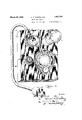
- 1 is a perspective view of the assembled short Wave radio receiverl (set.
- Fig. 2 is aperspective view of the under side of the panel upon which are mountedV the operating parts.
- Fig. 3. is a diagrammatic view of the short Wave adapter circuit, fillustrating its' association VWith a standard broadcast receiver set.
- the short wave adapter set I has been illustrated substantially acters of reference throughout the ⁇ severalf full size.
- the operating parts are entirely supported upon a panel 1 with the inductances or coils and vacuum tube exposed on top of such panel, while the remaining parts are supported on the under side of the panel and are enclosed and protected Within a shallow housing or box 2 of Which the panel 1 forms the top.
- a shallow housing or box 2 Located adjacent to the top margin of the panel 1 and positioned side by side, is the vacuum tube or thermionic Valve 3 and the coils or inductances.
- These consist of a permanently mounted primary coil 4 consisting of a few turns of wire, usually three or four turns, one end of Which is permanently connected With the aerial binding post 5,
- the secondary and tickler Windings are of the ⁇ plug-in type.
- the secondary and tickler inductances or coils are mounted upon a .form having standard tube base prongs, for engagement in a standard tube mounting. .Tn the presentV instance this mounting consists of a group of spaced holes through Which the prongs 8 of the coil mounting may be projected into engagement With corresponding contact arms of Which 7 is one.
- the mounting for the tube 3 is preferably of the same form, that is, it comprises a group of holes 9 in the panel 1 through Which the tube base contact prongs arepondered into engagement with correspondingrly located arms 10 secured tothe under'side of the panel.
- the secondary and tickler inductance Windings upon the coil mounting 11 have their number of turns proportioned in accordance With the Wave band or frequency band to be received. Tn practice, a series of interchangeable inductance units, each having secondary and tickler Windings of different capacities are interchangeably employed. Interposed between the inductance coil mountingr and the tube mounting is a grid condenser 12 upon which is supported the usual grid leak 13. This grid condenser and grid leak 12-13 are directly connected with the grid contact. arm 10a of the tube mounting atone side and correspondingly directly connected with the contact arm 7a of. the inductance mounting at the opposite side. The inductance coil and tube are so located that the interconnection between the contact arms 7 a and 10a may be made solely by the condenser and grid leak unit 12-13 without the necessit-y of intervening Wire connection.
- a choke coil 14 in the plate circuit of the tube 3 is located immediately below the tube mounting.
- One of the supporting studs 15 for such choke coil may afford a direct connection With the plate contact arm of the tube mounting Which is concealed beneath the choke coil 14.
- this choke coil consists of approximately one hundred and tWenty-five turns of #30 Wire wound random on an inch and a quarter form. These dimensions and number of turns, as Well as those of the primary coil 4 are given merely for illustrat-ive purposes and convenience of those Who may have occasion to constructthis device, and not with any intention of limiting ⁇ the invention to any specific Winding or relative proportion of inductances Which obviously may be varied in accordance With the Wave band or group of radio frequencies to be received.
- the control of the set is efi'ected by means of two variable condensers of approximately m. m. f. capacity.
- the condenser 17 is the primary or tuning condenser, one side of Which, preferably the rotor side, is connected With the A minus or negative contact arm 10b of the tube mounting, While the opposite side, preferably the stator side, is connected With the contact arm 7 a pertaining to the secondary inductance, Which is also common to one side .'of the condenser and grid leak unit 12-13.-
- This condenser 17 is controlled by an adjusting knob 18 located on the exterior side of the panel 1 Which simultaneously controls a dial 19 to indicate the relative adjustment of the condenser.
- control knob 18 is located in proximate relation With the lower marginal edge of the panel 1 in distantly spaced relation With the group of super-sensitive elements assembled adjacent to the top margin of the panel and also in offset relation With the tuning coudenser.
- the location of the adjusting knob 18 is such that the operator-,s hand is most conveniently positioned beyond the limit of the receiver set With only his fingers overhanging the panel. Further when grasping the knob 18 the operatoris fingers are as distantly removed from the tuning condenser 17 and from the assembly at the opposite end of the panel, as is convenient or practicable.
- Regeneration is controlled by a second condenser 20, one side, Jreferably the rotor side, of Which is also connected with the negative or A minus contact arm 106 of the tube mounting by the connection 21 which also connects it With the primary or tuning condenser 17.
- the opposite side of the regeneration control condenser 20, which is preferably the i stator side, is connected With'the contact arm 7 b of the inductance mounting, which comprises one terminal of the tickler coil.
- the opposite terminal of the tickler Winding With Which the contactarm 70 makes engagement is connected from such contact arm 70 through the ,connection-24 Withx the connection 15 of the choke coil 14 which is also directly connected With .the plate terminal of the tube 1 .A three 'conductorcable 25 connects with lthe .contact armsV and 107) comprising Vthe .filamentl plus and negative of the tube 3, While the 'third conductor Vleads to the terminal .26 vof the choke coil 14 and forms a part of the plate circuit.
- the short wave adapter hereinbefore described Will .operate as a detector lfor receiving high fre'quency'or short Wave Signals. It lWill utilize.v the audio frejuency amplification system of 'the broadcast receiver, and Will afford a vcompleteshort Wave radio receiver of very good operating characteristics.
- the radi'ofrequency and detector portions of the broadcast receiver set being.
- the receiver set serves as an intermediate radio frequency amplifier, a second detector and audio amplifier, thus forming in combination a super-heterodyne type of receiver.
- a super-heterodyne broadcast receiver is employed in conjunction with this short Wave adapter, the plug 27 is inserted into the first detector socket Vof such superheterodyne receiver, and the operation is as before described. It is thus possible by use the short Wave adapter set heretofore described to convert any type of receiver into a received for high frequency or short ⁇ Wave Signals, utilizing the short Wave adapter -set heretofore described as the first tuned or detector tube, utilizing the broadcast receiver set for amplifying the short Wave signals received.
- the interconnectionbetween the component parts of the short Wave adapter set are either directly made as in the case of the condensergrid leak unit 12-13 With the inductance and tube mounting, and the choke coil 14 With the plate connection of the tube mounting, or all such connections are made as short aspossible With the use of Wire as small as possible in order 'to reduce to a minimum the surface f area.
- the lcomponent parts are designed to perform ltheir various functions, but at the same timeV their surface areas arefreduced to minimum, and likewise the ,live side, that is the side at radiofrequency potential, disposed as far away from the operating or control knobs 'as is possible, and also presenting such live or radio frequencypotential side of the element as close as possible to the parts'to Which it is connected in order to reduce the length of connecting Wire.
- Thel various parts including the coils are'smalland compact in order to reduce, so far as possible, their external field.
- VlVhile the circuit 'of the short Wave receiver isy not a newcircuit per se, and while r in construction standard commercial partsand accessories are employed, by careful and scientific design in the assembly and association of b,parts and' their mountings, V there has been produced a short Wave receiver standard broadcastreceiving set 'Which Will operate successfully under ordinary conditions and does not possess the peculiar, erratic and undesirable characteristics ofran ordinary short Wave receiver set operating under such conditions. 1
- a mounting panel including a mounting panel, a vacuum detect-01' tube mounted ez-:teriorly adjacent to one end of said panel, a removable inductance unit containing secondary and tickler coils also mounted exteriorly of the panel in closely spaccd relation With the vacuum tube.
- a condenser grid leak unit mounted upon the reverse side of the panel in closely connected relation intermediate the tube and inductance mountings, a cholie coil located in intimate relation With the tube mounting,
- said elements form a closely associated group
- a tuning condenser and a regeneration control cendenser located on the reverse side of the panel in distantly spaced relation
- said ygroup of elements and control knobs for said condensers located on the face of the panel in closely spaced relation With the margin of the panel Whereby the operators hands, when operating' such knobs, Will be positioned beyond the limit of the set With only his fingers overhanging the panel.
- a short Wave adapter for detachable interconnection With a standard broadcast receiver se;,i1icluding a mounting panel, a dctach able inductance unit lnounted thereon, a primary inductance coil permanently mounted on said panel surfounding the removable inductance unit, any one of a series of interchangeable inductance units being interchangeably engageable Within the perm nently positioned primary coil, a vacuum detector tube and a condenser grid leak unit, said parts being assembled in closely grouped r 3lation, and control mean therefor positioned in closely spaced relation with the margin of the panel Whereby the operator's hand Will be positioned beyond the limit of the adapter with only his iin gers overhanging the adapter When ope ⁇ ating such control.
- a short Wave adapter for detachable intel-connection With a standard broadcast receiver set, a mounting panel, an inductance unit and a vacuum detector tube mounted side by side adj acent to one end of the panel, a pair of control condensers mounted side by side in spaced relation With the inductance unit and vacuum tube, a control knob for one condenser located in closely spaced relation With one margin of the panel, a control knob for the other condenser located in offset relation with the condenser, and in closely spaced relation With another margin of the panel.
- a short Wave radio receiver including a mountin g panel having two groups of spaced holes there-in agreeing With the positions of the contact prongs of standard vacuum tube base, contact arms secured to the reverse side of the panel in overlapping relation With the holes, a vacuum tube engageable in one set of holes the prongs of Which contact With the corresponding arms, an interchaugeable plug-in inductance unit having secondary and tickler windings and contact prongs correspon ding With those of a standard vacuum tube engageable the holes of the other group With its prongs contacting the corresnonding contact arms, an intermediately positioned condenser grid leak unit having direct contact connection with the tube grid contact arm and With a secondary Winding inductance contact arm, a primary inductance coil permanently mounted upon the panel in concentric relation With the interchangeable inductance unit and fixedly connected at one end With the contact arm pertaining to the f-iecondary Winding of the inductance unit and at its opposite end With an antenna connection, a circuit in Which said
- a panel a tube mounting including contacts engageable With the contact prongs; of a vacuum tube base on the under side of said panel, an induct-ance mounting including contacts engageable With contact prongs upon a removable inductance unit on the under side of said panel in closely spaced relation With the tube mounting contacts, the panel having openings therein through Which a va cuum tube and an inductance are detachablv engageable With said contact pl'ongs, a grid-leak condenser mounting directly connected With the grid contact of the tube mounting and likewise directly connected With one of the contacts ⁇ of the inductance unit mounting, a tuning condenser bridging two of the inductance mounting contacts and simultaneously bridgincf two of the tube n'zounting contacts through the ⁇ grid-leak condenser mounting, a regreneration control condenser bridging two of the inductance mounting contacts including one of the 'contacts With Which the tuning condenser is connected,
- a radio short Wave adapter the. combination With tuning means and current supply means, of a vacuum tube mounting and a mounting for a detachable inductance unit, each including a plurality of contacts, and a choke coil directly connected to and supported by 'one of the vacuum tube contact connections.
- the com- I bination With tuning means and current supply means of a vacuum tube mounting and a mounting for a detachable inductance unit each including a group of 4contact elements, said mountings 1 being located inl closely spaced relation, and a grid-leak condenser unit interposed between said tube and inductance mountings and having direct bridging connectioniwith a contact element of each mounting.
- vvithtuning means and current supply means of a. vacuum tube mounting and a mounting for a Vdetachable inductance unit, each including a group of contact elements engageable With contact prongs upon the tube base and inductance unit; a grid-leak condenser unit interconnecting a contact of each mounting, and a choke coil supported upon a contact of the vacuum tube mounting.
- the combination with tuning means and current supply means of a vacuum tube mounting and a mounting for a detachable inductance unit; operative connections between the respective mountings and the tuning Vand current supply means; a removable inductance unit including secondary and tickler Windings; and
- a short Wave radio reveiver the g combination with tuning means and current supply means; of a mounting panel havingl therein spaced groups of holes tox receive contact prongs; of a vacuum tube base in the holes of one group and terminal contact prongsof a detachable inductance unit in ⁇ the holes of the other group; independent spring contact arms secured to the under side of said panel and extending into overlapping relation with the different holes of said groups; a grid-leak condenser unit; attachment means common to a contact arm pertaining to a hole of each group and said unit for attaching said grid-leak condenser unit to said panel and simultaneously interconnecting said arms through the grid-leak condenser unit. :one to the other.
Landscapes
- Engineering & Computer Science (AREA)
- Computer Networks & Wireless Communication (AREA)
- Signal Processing (AREA)
- Details Of Connecting Devices For Male And Female Coupling (AREA)
Description
March 29, 1932. E, 'Tj FLEWELUNG 1,851,354
SHORT WAVE ADAPTER Filed 0012. '15, 19 28 2 Sheets-Sheet 2 c l fa? -2 AF j/z /2 V Patented LMan 29*, 1932 UNirEo STATES RATENT, osaica vIEJJIVIUITID.T; FLEWELLING, OF DAYTON, OHIO:
SHORT WAvii ADAPTER Application filed October 15,1928. I Serial No. 312,623.
My invention relates to radio receivingapparatus, and more particularly to an auxiliary short Wave receiving apparatus rfor use with the usual broadcast receivingset, Whereby short'wave transmission maybe received and amplified Without unnecessary duplication of parts and apparatus. Y Short' wave or high frequency yreception,
that is impulses from three thousand to thirty and methods @of 'interconnection of the various parts, and by locationxofthecontrol element in suchposition that the operator's hand Will be outside the Velectrical fieldf'of super-,sensitive elements'or in such position as to minimize the efiectof body capacity.
The short Wave receiver, forming the subject matter hereof, comprises a one tube regenerative circuit fitted lwith a connecting cable enabling it to be Ffplug'gedi,x into a. standardtube socket of an ordinary broadcast receiver from which current will be supplied at the necessary voltages for the opern ation of the short wave apparatus, known as an uadapter. When connected into Vthe det'ector socket of a broadcast receiver, the au- Vdio amplifyingcircuits of suchreceiver are xemployed in conjunction With the short wave adapter to afiford a complete short wave .re'- ceiverof good-operative'characteristics. By connecting theshort wave adapter into the first radio frequencyx tube socket of aradio frequency amplifying receiver and'allowing the short wave adapter `tube to oscillatefat a frequency equal to that of the signal desired V plus or minusV the frequency to which the a broadcast receiver is tuned, the broadcastV Vother parts.
is designed to; over'-,V
receiver is converted into a short Waveheterodyne type of receiver.
The object of theinvention is to Simplify the construction as Wellx as theV means andE mode of operation of high frequencyor short c wave radio'receiving sets whereby theywill -not Vonly be cheapenedin' construction, but
Will be more efficient in operation, of good operating characteristics,v uniform in action, easily controlled, and unlikely to `get out of: order. 1
A'furth'er and important object of thein- Vvention is to provide Vmeans bywhich anorpdinary `broadcast receiving set may be' convertedintofla high frequency or short wavel receiver at minimum'-cost and Without disturbance or rearrangement of vthe circuit or A further and quiteim'portantV feature of the invention is tol provide av simpleH and 1nexpensive 'formfof high frequency orx short wave receiver in Which the undesirableinfiuences of extraneous masses and body ,and hand capacityis minimizedandwherein the component parts are disposed ina well balanced assembly Which a novice is able to`use.` With comparative ease of operation.V
With the above primary and otherfincidental objects in view, as Will more fully appear in the specification, the invention iconl sists of the features of construction, the parts and' combinations thereof, and theimode of operation or their equivalents, as hereinafter;h described and set forth in the claims;
Referring Ito the accompanying drawings wherein is shown the preferred but obviously 1 not necessarily the only form of ei'nbodiment` of the invention, 1 is a perspective view of the assembled short Wave radio receiverl (set. Fig. 2 is aperspective view of the under side of the panel upon which are mountedV the operating parts. Fig. 3. is a diagrammatic view of the short Wave adapter circuit, fillustrating its' association VWith a standard broadcast receiver set.
Like parts are indicated by similar charviews.` n v V i In the original drawings, the short wave adapter set Ihas been illustrated substantially acters of reference throughout the` severalf full size. The operating parts are entirely supported upon a panel 1 with the inductances or coils and vacuum tube exposed on top of such panel, while the remaining parts are supported on the under side of the panel and are enclosed and protected Within a shallow housing or box 2 of Which the panel 1 forms the top. Located adjacent to the top margin of the panel 1 and positioned side by side, is the vacuum tube or thermionic Valve 3 and the coils or inductances. These consist of a permanently mounted primary coil 4 consisting of a few turns of wire, usually three or four turns, one end of Which is permanently connected With the aerial binding post 5,
.While the opposite end of such primary coil is connected With a contact arm t on the under side of the, panel 1, Which arm is common to both the secondary Winding and tickler Winding, being connected to the latter through a regeneration control condenser.
The secondary and tickler Windings are of the` plug-in type. For convenience and economy of manufacture, and interchangeability With other coils having different numbers of turns, the secondary and tickler inductances or coils are mounted upon a .form having standard tube base prongs, for engagement in a standard tube mounting. .Tn the presentV instance this mounting consists of a group of spaced holes through Which the prongs 8 of the coil mounting may be projected into engagement With corresponding contact arms of Which 7 is one. The mounting for the tube 3 is preferably of the same form, that is, it comprises a group of holes 9 in the panel 1 through Which the tube base contact prongs are proiected into engagement with correspondingrly located arms 10 secured tothe under'side of the panel. The secondary and tickler inductance Windings upon the coil mounting 11 have their number of turns proportioned in accordance With the Wave band or frequency band to be received. Tn practice, a series of interchangeable inductance units, each having secondary and tickler Windings of different capacities are interchangeably employed. Interposed between the inductance coil mountingr and the tube mounting is a grid condenser 12 upon which is supported the usual grid leak 13. This grid condenser and grid leak 12-13 are directly connected with the grid contact. arm 10a of the tube mounting atone side and correspondingly directly connected with the contact arm 7a of. the inductance mounting at the opposite side. The inductance coil and tube are so located that the interconnection between the contact arms 7 a and 10a may be made solely by the condenser and grid leak unit 12-13 without the necessit-y of intervening Wire connection.
A choke coil 14 in the plate circuit of the tube 3 is located immediately below the tube mounting. One of the supporting studs 15 for such choke coil, may afford a direct connection With the plate contact arm of the tube mounting Which is concealed beneath the choke coil 14. In practice, this choke coil consists of approximately one hundred and tWenty-five turns of #30 Wire wound random on an inch and a quarter form. These dimensions and number of turns, as Well as those of the primary coil 4 are given merely for illustrat-ive purposes and convenience of those Who may have occasion to constructthis device, and not with any intention of limiting` the invention to any specific Winding or relative proportion of inductances Which obviously may be varied in accordance With the Wave band or group of radio frequencies to be received. By the assembly thus far described, the supersensitive elements of the set are closely connected in group relation adjacent to one end of the panel, and comparatively distantly lo` cated from the manually operablc control devices.V
The control of the set is efi'ected by means of two variable condensers of approximately m. m. f. capacity. The condenser 17 is the primary or tuning condenser, one side of Which, preferably the rotor side, is connected With the A minus or negative contact arm 10b of the tube mounting, While the opposite side, preferably the stator side, is connected With the contact arm 7 a pertaining to the secondary inductance, Which is also common to one side .'of the condenser and grid leak unit 12-13.- This condenser 17 is controlled by an adjusting knob 18 located on the exterior side of the panel 1 Which simultaneously controls a dial 19 to indicate the relative adjustment of the condenser. It Will be noted that the control knob 18 is located in proximate relation With the lower marginal edge of the panel 1 in distantly spaced relation With the group of super-sensitive elements assembled adjacent to the top margin of the panel and also in offset relation With the tuning coudenser. By such arrangement the operatorls hand is removed as far distant as possible from the elements subject to influence of body or hand capacity. The location of the adjusting knob 18 is such that the operator-,s hand is most conveniently positioned beyond the limit of the receiver set With only his fingers overhanging the panel. Further when grasping the knob 18 the operatoris fingers are as distantly removed from the tuning condenser 17 and from the assembly at the opposite end of the panel, as is convenient or practicable.
, Regeneration is controlled by a second condenser 20, one side, Jreferably the rotor side, of Which is also connected with the negative or A minus contact arm 106 of the tube mounting by the connection 21 which also connects it With the primary or tuning condenser 17. The opposite side of the regeneration control condenser 20, which is preferably the i stator side, is connected With'the contact arm 7 b of the inductance mounting, which comprises one terminal of the tickler coil. The opposite terminal of the tickler Winding With Which the contactarm 70 makes engagement, is connected from such contact arm 70 through the ,connection-24 Withx the connection 15 of the choke coil 14 which is also directly connected With .the plate terminal of the tube 1 .A three 'conductorcable 25 connects with lthe .contact armsV and 107) comprising Vthe .filamentl plus and negative of the tube 3, While the 'third conductor Vleads to the terminal .26 vof the choke coil 14 and forms a part of the plate circuit.
' The opposite end of the conductor cable is connected lwith a plug l27 having contact prongs agreeing With those of a standard tube base, and adaptable to be vplugged,into any standard tube socket. The filament positive and negative Conductors are connected With the corresponding prongs 28 and 29 of the plug 27, While the `plate circuit conductor is connected With the usual plate contact prong 30 of such plug; By this arrangement, When the plug V27 is inserted in any standard tube socket of a-broadcast receiving set, current V is supplied throughthe contact prongs 28 and 29 to the filament `of the tube 3 ofthe short wave adapter, While the plate of such tube is interconnected through the choke coil 14 With the plate circuit of such broadcast receiver 'kao set.
When the plug 27 is'inserted into the detector socket of any standard broadcast radio receiver, the short wave adapter hereinbefore described Will .operate as a detector lfor receiving high fre'quency'or short Wave Signals. It lWill utilize.v the audio frejuency amplification system of 'the broadcast receiver, and Will afford a vcompleteshort Wave radio receiver of very good operating characteristics.
In such case, the radi'ofrequency and detector portions of the broadcast receiver set being.
unused,'such set is not tuned,flbut all tuning is effect-ed by adjustment of* thecondenser 17 by meansof the knob 18', the variations being indicated by thedial 19, of the short Wave adapter set. lRegeneration iscontrolled by the condenser 20, Which upon the face of the panel 1 is provided With an adjusting knob *22. It is tofbe noted that thejknob 22 for controlling Vthe regeneration condenser 20. like the, control knob 18, is ,located'inflproximate- 'relation Withthe margin of the panel 1, so that in convenient operating position the operators hand does not overhangthepanel, but is rather offset to one side With only the operatorls fingers positioned above the VpanelV to grasp the knob 22. This arrangement of the 1 knobs 18 and 22 keeps the' operatorls hand as far removed'as practic'able from the field of .not onlyft-he condensers 17 and 20 but also the assembly near the top margin'of the panel.
receiver set serves as an intermediate radio frequency amplifier, a second detector and audio amplifier, thus forming in combination a super-heterodyne type of receiver. In the event that a super-heterodyne broadcast receiver is employed in conjunction With this short Wave adapter, the plug 27 is inserted into the first detector socket Vof such superheterodyne receiver, and the operation is as before described. It is thus possible by use the short Wave adapter set heretofore described to convert any type of receiver into a received for high frequency or short `Wave Signals, utilizing the short Wave adapter -set heretofore described as the first tuned or detector tube, utilizing the broadcast receiver set for amplifying the short Wave signals received.
The interconnectionbetween the component parts of the short Wave adapter set are either directly made as in the case of the condensergrid leak unit 12-13 With the inductance and tube mounting, and the choke coil 14 With the plate connection of the tube mounting, or all such connections are made as short aspossible With the use of Wire as small as possible in order 'to reduce to a minimum the surface f area. .The lcomponent parts are designed to perform ltheir various functions, but at the same timeV their surface areas arefreduced to minimum, and likewise the ,live side, that is the side at radiofrequency potential, disposed as far away from the operating or control knobs 'as is possible, and also presenting such live or radio frequencypotential side of the element as close as possible to the parts'to Which it is connected in order to reduce the length of connecting Wire. Thel various parts including the coils are'smalland compact in order to reduce, so far as possible, their external field. VlVhile the circuit 'of the short Wave receiver isy not a newcircuit per se, and while r in construction standard commercial partsand accessories are employed, by careful and scientific design in the assembly and association of b,parts and' their mountings, V there has been produced a short Wave receiver standard broadcastreceiving set 'Which Will operate successfully under ordinary conditions and does not possess the peculiar, erratic and undesirable characteristics ofran ordinary short Wave receiver set operating under such conditions. 1
' capable' of operation inl conjunction With a From the above description it will be apparent that th .re is thus provided a device of the character described possessing the particular Vfeatures of advantage before enumerated as desirable, but Which obviously is susceptible of mofflification in its form, proportions, detail construction and arrangement of parts Without departing from the principle involved or sacriflcing any of its adVant-ages.
VVhile in order to comply With the statute the invention has been described in language more or less specific as to structural features, it is to be understood that the invention is not limited to the specific details shown, but that the means and construction herein disclosed comprise the preferred form. of several modes of putting the invention into effect and the invention is, therefore, claimed in any of its forms or mooificaf'ions Within. the legitimate and. valid scope of the appended claims.
Having thus described my invention, I claim:
l. In a radio receiver, a short Wave adapter for interconnection With a broadcast receiver,
' including a mounting panel, a vacuum detect-01' tube mounted ez-:teriorly adjacent to one end of said panel, a removable inductance unit containing secondary and tickler coils also mounted exteriorly of the panel in closely spaccd relation With the vacuum tube., a condenser grid leak unit mounted upon the reverse side of the panel in closely connected relation intermediate the tube and inductance mountings, a cholie coil located in intimate relation With the tube mounting, Whereby said elements form a closely associated group, a tuning condenser and a regeneration control cendenser located on the reverse side of the panel in distantly spaced relation With said ygroup of elements, and control knobs for said condensers located on the face of the panel in closely spaced relation With the margin of the panel Whereby the operators hands, when operating' such knobs, Will be positioned beyond the limit of the set With only his fingers overhanging the panel.
2. In a radio receiver, a short Wave adapter for detachable interconnection With a standard broadcast receiver se;,i1icluding a mounting panel, a dctach able inductance unit lnounted thereon, a primary inductance coil permanently mounted on said panel surfounding the removable inductance unit, any one of a series of interchangeable inductance units being interchangeably engageable Within the perm nently positioned primary coil, a vacuum detector tube and a condenser grid leak unit, said parts being assembled in closely grouped r 3lation, and control mean therefor positioned in closely spaced relation with the margin of the panel Whereby the operator's hand Will be positioned beyond the limit of the adapter with only his iin gers overhanging the adapter When ope `ating such control.
3. In a radio receiver, a short Wave adapter for detachable intel-connection With a standard broadcast receiver set, a mounting panel, an inductance unit and a vacuum detector tube mounted side by side adj acent to one end of the panel, a pair of control condensers mounted side by side in spaced relation With the inductance unit and vacuum tube, a control knob for one condenser located in closely spaced relation With one margin of the panel, a control knob for the other condenser located in offset relation with the condenser, and in closely spaced relation With another margin of the panel.
A short Wave radio receiver, including a mountin g panel having two groups of spaced holes there-in agreeing With the positions of the contact prongs of standard vacuum tube base, contact arms secured to the reverse side of the panel in overlapping relation With the holes, a vacuum tube engageable in one set of holes the prongs of Which contact With the corresponding arms, an interchaugeable plug-in inductance unit having secondary and tickler windings and contact prongs correspon ding With those of a standard vacuum tube engageable the holes of the other group With its prongs contacting the corresnonding contact arms, an intermediately positioned condenser grid leak unit having direct contact connection with the tube grid contact arm and With a secondary Winding inductance contact arm, a primary inductance coil permanently mounted upon the panel in concentric relation With the interchangeable inductance unit and fixedly connected at one end With the contact arm pertaining to the f-iecondary Winding of the inductance unit and at its opposite end With an antenna connection, a circuit in Which said inductance unit and vacuum tube contacts are included and tuning means for said circuit mounted on said panel.
5. In a short wave radio receiver, a panel, a tube mounting including contacts engageable With the contact prongs; of a vacuum tube base on the under side of said panel, an induct-ance mounting including contacts engageable With contact prongs upon a removable inductance unit on the under side of said panel in closely spaced relation With the tube mounting contacts, the panel having openings therein through Which a va cuum tube and an inductance are detachablv engageable With said contact pl'ongs, a grid-leak condenser mounting directly connected With the grid contact of the tube mounting and likewise directly connected With one of the contacts` of the inductance unit mounting, a tuning condenser bridging two of the inductance mounting contacts and simultaneously bridgincf two of the tube n'zounting contacts through the `grid-leak condenser mounting, a regreneration control condenser bridging two of the inductance mounting contacts including one of the 'contacts With Which the tuning condenser is connected, a choke coil supported upon the tube mountlng, and a plug-in multi-cable connection for supplying filament and plate current to the tube mounting contacts.
6. In a radio short Wave adapter, the. combination With tuning means and current supply means, of a vacuum tube mounting and a mounting for a detachable inductance unit, each including a plurality of contacts, and a choke coil directly connected to and supported by 'one of the vacuum tube contact connections.
7 In a radio short Wave adapter, the com- I bination With tuning means and current supply means, of a vacuum tube mounting and a mounting for a detachable inductance unit each including a group of 4contact elements, said mountings 1 being located inl closely spaced relation, and a grid-leak condenser unit interposed between said tube and inductance mountings and having direct bridging connectioniwith a contact element of each mounting.
8. In a radio short Wave adapter, the combination vvithtuning means and current supply means, of a. vacuum tube mounting and a mounting for a Vdetachable inductance unit, each including a group of contact elements engageable With contact prongs upon the tube base and inductance unit; a grid-leak condenser unit interconnecting a contact of each mounting, and a choke coil supported upon a contact of the vacuum tube mounting.
9. Ina short Wave radio receiver, the combination with tuning means and current supply means, of a vacuum tube mounting and a mounting for a detachable inductance unit; operative connections between the respective mountings and the tuning Vand current supply means; a removable inductance unit including secondary and tickler Windings; and
a primary coil permanently mounted concentrically With the inductance unit mounting, Within which the removableinductance unit f projects When connected With its mounting.
10. In .a short Wave radio reveiver, the g combination with tuning means and current supply means; of a mounting panel havingl therein spaced groups of holes tox receive contact prongs; of a vacuum tube base in the holes of one group and terminal contact prongsof a detachable inductance unit in` the holes of the other group; independent spring contact arms secured to the under side of said panel and extending into overlapping relation with the different holes of said groups; a grid-leak condenser unit; attachment means common to a contact arm pertaining to a hole of each group and said unit for attaching said grid-leak condenser unit to said panel and simultaneously interconnecting said arms through the grid-leak condenser unit. :one to the other.
Priority Applications (1)
| Application Number | Priority Date | Filing Date | Title |
|---|---|---|---|
| US312623A US1851354A (en) | 1928-10-15 | 1928-10-15 | Short wave adapter |
Applications Claiming Priority (1)
| Application Number | Priority Date | Filing Date | Title |
|---|---|---|---|
| US312623A US1851354A (en) | 1928-10-15 | 1928-10-15 | Short wave adapter |
Publications (1)
| Publication Number | Publication Date |
|---|---|
| US1851354A true US1851354A (en) | 1932-03-29 |
Family
ID=23212288
Family Applications (1)
| Application Number | Title | Priority Date | Filing Date |
|---|---|---|---|
| US312623A Expired - Lifetime US1851354A (en) | 1928-10-15 | 1928-10-15 | Short wave adapter |
Country Status (1)
| Country | Link |
|---|---|
| US (1) | US1851354A (en) |
Cited By (1)
| Publication number | Priority date | Publication date | Assignee | Title |
|---|---|---|---|---|
| US2507995A (en) * | 1947-11-12 | 1950-05-16 | Avco Mfg Corp | Television receiving system |
-
1928
- 1928-10-15 US US312623A patent/US1851354A/en not_active Expired - Lifetime
Cited By (1)
| Publication number | Priority date | Publication date | Assignee | Title |
|---|---|---|---|---|
| US2507995A (en) * | 1947-11-12 | 1950-05-16 | Avco Mfg Corp | Television receiving system |
Similar Documents
| Publication | Publication Date | Title |
|---|---|---|
| US2341345A (en) | Tuning system | |
| GB651289A (en) | Radio apparatus | |
| US1851354A (en) | Short wave adapter | |
| US1965202A (en) | Shielding means for radio apparatus | |
| US2100402A (en) | Multiband inductance unit | |
| US2312211A (en) | Tuning system | |
| Harnett et al. | The design and testing of multirange receivers | |
| US2028534A (en) | Variable-selectivity radio receiver | |
| US1938656A (en) | Audion amplifier | |
| US2179298A (en) | Signal system | |
| US1937099A (en) | Radio receiving apparatus | |
| US2650298A (en) | Television booster circuits | |
| US2507995A (en) | Television receiving system | |
| US2075501A (en) | Radio receiving system | |
| US2598247A (en) | Television tuning apparatus with channel selecting switch | |
| US1746754A (en) | Electrical system and device | |
| US1850846A (en) | Push rod system for tuning radio circuits | |
| US2236982A (en) | Coupling device | |
| US1875140A (en) | Radio receiving apparatus | |
| US2074447A (en) | Control device for radio receivers | |
| US1666505A (en) | Radio appliance | |
| US1658562A (en) | Radio receiving apparatus | |
| US2610299A (en) | Electrical apparatus | |
| US2111763A (en) | Radio receiver | |
| US1831519A (en) | Radio receiving system |