US1851353A - Soffit hanger - Google Patents
Soffit hanger Download PDFInfo
- Publication number
- US1851353A US1851353A US358896A US35889629A US1851353A US 1851353 A US1851353 A US 1851353A US 358896 A US358896 A US 358896A US 35889629 A US35889629 A US 35889629A US 1851353 A US1851353 A US 1851353A
- Authority
- US
- United States
- Prior art keywords
- hanger
- bolt
- concrete
- nut
- members
- Prior art date
- Legal status (The legal status is an assumption and is not a legal conclusion. Google has not performed a legal analysis and makes no representation as to the accuracy of the status listed.)
- Expired - Lifetime
Links
- 238000010276 construction Methods 0.000 description 11
- 125000006850 spacer group Chemical group 0.000 description 11
- 239000002184 metal Substances 0.000 description 5
- 230000000295 complement effect Effects 0.000 description 4
- 238000012986 modification Methods 0.000 description 3
- 230000004048 modification Effects 0.000 description 3
- CZTQRSPXKRZGAN-UHFFFAOYSA-N 2-chloro-n-(2,6-diethylphenyl)-n-(2-propoxyethyl)acetamide;4,6-dichloro-2-phenylpyrimidine Chemical group ClC1=CC(Cl)=NC(C=2C=CC=CC=2)=N1.CCCOCCN(C(=O)CCl)C1=C(CC)C=CC=C1CC CZTQRSPXKRZGAN-UHFFFAOYSA-N 0.000 description 2
- 229910000831 Steel Inorganic materials 0.000 description 2
- 238000004519 manufacturing process Methods 0.000 description 2
- 239000010959 steel Substances 0.000 description 2
- 241001222009 Beamys Species 0.000 description 1
- 101100379079 Emericella variicolor andA gene Proteins 0.000 description 1
- 241001071861 Lethrinus genivittatus Species 0.000 description 1
- 229910000746 Structural steel Inorganic materials 0.000 description 1
- 238000005266 casting Methods 0.000 description 1
- 230000000694 effects Effects 0.000 description 1
- 238000009415 formwork Methods 0.000 description 1
- 239000000463 material Substances 0.000 description 1
- 238000005259 measurement Methods 0.000 description 1
- 238000000034 method Methods 0.000 description 1
- 230000002787 reinforcement Effects 0.000 description 1
Images

Classifications
-
- E—FIXED CONSTRUCTIONS
- E04—BUILDING
- E04G—SCAFFOLDING; FORMS; SHUTTERING; BUILDING IMPLEMENTS OR AIDS, OR THEIR USE; HANDLING BUILDING MATERIALS ON THE SITE; REPAIRING, BREAKING-UP OR OTHER WORK ON EXISTING BUILDINGS
- E04G17/00—Connecting or other auxiliary members for forms, falsework structures, or shutterings
- E04G17/18—Devices for suspending or anchoring form elements to girders placed in ceilings, e.g. hangers
Definitions
- Thisy invention relates to concrete lforms and the vliliefand more particularly to a hanger forvsuspending ormportions inl predeterininedspaced relation beneatha structural beam or other support.
- the several parts are adj usted by the hanger bolt which engages With'a nut carried by tlienpper jaw carrying member;
- the beam engaging portion and 'also the hanger bolt nut are permanently em- 3() bedded ⁇ in the concrete.
- the bolt being subsequently removedenables the embedded nut and beam engaging portion ⁇ to be utilized as an insert for securingA overhead structures n such asline shatting,-hangers, brackets and other structures to the ceiling.
- the objectf'oii the invention is to simplify thestructure as well as the means and mode of operation of such soiiit'or beam hangers for concrete forms whereby they will not only be 4o cheapened in construction but will be more efficient in use, strong, durable, affording positive-engagement with the structural supportingbeam, adapted to automatically gauge the thickness ofthe encasingbody of concrete,
- a further object of theinvention is to provide a replenish hanger orthe like'having gripper means for ⁇ iXedly securing such hanger to a structural beam orothersupport.
- a furtherv object ⁇ of the invention isto provider a somt hanger orv thelike'ha'ving ⁇ v parts for permanent* embedment Withinthe concrete body Whichmaybe subsequent-l 6U lyr utilized as an attachment insert forf'se curing einxraneousy bodies to lthe concretestructure;
- a further object ofthelinvention is to pro'- vide a. sotiitrhanger wherein ya removable.
- hanger bolt- is utilized for rigidly andy iiiedly' clamping the hanger to gafstructural'fbeani" and? the 'concrete form in predetermined* relation with such beam.
- the invention consists. of the features oi' construction, the parts and combinations thereof andthe mode ofopera'tion ory their'equivalents as hereinafter described and set forth in the'claims'.
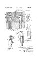
- Fig. l is an l'end-elevation so ⁇ partially in section of a'sofit form supported upon a structural beam bythe 'hangerforming ythe subject matter hereof'.
- Fig. 2 is a detail perspective Viewof a soiiit or overhead beam comprising4 aconcrete encasedk struc- 85 tural beam from-Which the lform has been" removed.
- Fig. 3 is a detailjperspective view yci?l one of :the gripper members whichcarries the upperor overhanging jaw.
- Fig. Li is a similar perspeotiveviewof: ⁇ th complementary gripper member telescopically engageable vwithin thatshowniin Figa' 3- and carryingthe lower complementary jaw.'
- FIG. 7 is a perspective view of the tele seopically engaged gripper members formed from sheet material.
- Fig. 8 is a top plan vieu of the assembled hanger parts illustrated in Fig. 5.
- Fig. 9 is a front elevation thereof viewed from the right of Fig. 5.
- Fig. 10 is a vertical sectional View of the assembled hanger, wherein the hanger bolt nut is embedded Within one of t Le tubular jaw carrying members.
- 1 is a structural beam of the skeleton building ⁇ structure which is to be encased in concrete as indicated at 2. Enclosing the structural beam 1 is a sofiit form comprising the bottom portion 3 and sides 4 which are supported at intervals upon transverse cleats 5.
- hangers for the concrete form are shown engaged With the opposite margins of the supporting beam flange. These hangers may be oppositely disposed relative to each other or may be staggered throughout the length of the form as may be found most suitable, and in accordance With the size and Weight of the form and concrete deposit 2.
- Each of the form hangers comprises a hanger bolt 6 upon which are slidingly mounted two telescopic tubular members 7 and 8. In the construction shown in Figs.
- the tubular member 8 is enclosed within the member 7.
- the member 7 is provided with a laterally extending jaw 9 which overhangs the fiange of the beam 1 while the relatively reciprocat-ory member 8 is provided with a complementary jaw 1() engageable with the under side of the beam 1 and coacting with the j aw 9 to grip such beam flange.
- the tubular member 7 is longitudinally slotted at 11 to accommodate the jaw 10 of the member 8.
- rIhe member 8 is of such length as to serve as a spacer or spreader which predetermines the thickness of the deposit of concrete intermediate the underside of the beam 1 and the bottom of the form.
- This tubular member 8 abuts at its lower end upon the inner face of the bottom of the form 2, While its laterally projecting j aw 10 abuts upon the under side of the beam.
- a nut 12 for the hanger bolt 6 engages With the upper end of the tubular member 7 and as the bolt 6 is tightened relative to such nut, the parts are drawn into clamping engagement with each other. By tightening the bolt 6 relative to the nut 12, the bottom ,2 of
- the form is drawn upwardly against the spacer member 8, the aW 10 of which is thus forced against the flange of the beam 1 While at the same time the member7 is retracted downwardly drawing its jaw 9 into firm gripping engagement with the upper side of the beam flange.
- the beam fiange is securely gripped between the jaws 9 and 10 and the concrete form is firmly clamped in its adjusted relation with the beam 1, its approach to which is limited by the interposed spacer member 8.
- the member 7 is provided with a. laterally ext-ending finger 13 abutting upon the margin of the fiange of the supporting beam and resisting rotary motion.
- the latter can be removed by unscrevving the hanger bolts 6 from the nuts 12 which are then embedded in the deposit 2 of concrete along ⁇ with the hanger members 7 and 8. These parts are permanently embedded and may subsequently be employed for the attachment of extraneous bodies to the concrete structure.
- the embedded members 7 and 8 not only afford secure anchorage for the nuts 12 but also provide a passage way through the concrete deposit to such nut 12 through which an attachment bolt may be subsequent-ly introduced for attaching a structure such as a line shaft hanger or the like to the building structure.
- Fig. 5 there is shown a modification wherein the relation of the members 7 and 8 is reversed.
- the tubular member 7 carrying the jaw 9 is dis ⁇ posed interiorly of the member 8 which carries the complemrntary jaw 10.
- the function and application of the members are the same as before described.
- Vvlhile the form of hanger members illustrated in Figs. 1 to 5 inclusive are especiallyy adapted to be formed as metallic castings, the preferable construction is that illustrated in Figs. 6 to 10 inclusive, wherein such members are formed from sheet metal stampings.
- the spacer member 8 is preferably oisposed exteriorly of the member 7 in the manner shown in Fig. 5 and in subsequent figures of the drawing.
- the tubular member 7 is preferably not exactly cylindrical in cross sectional form in order that the exteriorly disposed tubular member 8 telescepically adjustable thereon may not be capable of rotary motion.
- the overhanging jaw 9 in such construction comprises parallel Wings formed integral with the tubular portion of the member 7 and projecting therefrom for'overhanging engagement with the flange of the structural beam 1.
- Such stamped metal jaw portion 9 is preferably though notnecessarily formed with indentaf members:areeincapable of relativel rota-ry moe.
- member f7 is; shaped: toA conform: lthereto sothat such tiomg thus@ maintaining .thet complementary jaar 10, ⁇ which. isY formed; by; bringingtogether vtriangular. extension Ofthemember 8, in ver# Y :tical alignment With'thejaw'portions 9. In- ⁇ stead of; leaivingi the; topof thefj aw? ,9" open,. as
- the member 8 is duo-functional, serving both as a spacer and as a gripper memb,er.-
- the adjustment of the bolt 6 rela- ;tive to the nut 12 axiallyl adjusts the members 7 and 8 to cause their jaws 9 and 10 to forcibly grip the flange of the beam 1 and at the same time the bolt fdraws the concrete form struc ture toward the ⁇ beam 1 until limited'by the @interposed spacery member 8 Where it is clamped by the tightening of such bolt 6.
- the present construction not only firmly and securely supports the concrete form, but
- beamy 1 would comprise anupright or standf-r 1 ard ofthe skeleton frame,.and theformiwalls' 3 and 4 would be vertically disposed. ⁇
- the Vhanger bolts may beinserted' from either .abovev or below. When inserted from above,.thex-stop lug orriblll: engages;
- v1'. ⁇ In a hanger forconcrete formsv and the like,.a-pair of telescopically adjustabletubu ⁇ larmembers, coacting jaws upon the respec-V tive members for clamping'engagement with., av support, and a hanger rbolt 1 extending. through the said members and engaging with a suspended form portion With which one. of; the adjustable members engages,A the adjustposition thek ohamfered. corners pass ⁇ easily;-
- a merge hanger for concrete forms a pair of tubular axially adjustable members, a
- clamp aws carriedby the respective members for clamping engagement with a support, the jaw of one of said members overhanging such support, the other member being interposed 25 5 between the form portion and the under side of the support as a spacer, the members being adjusted relative to each other to grip the support therebetween and the form portion being adjusted into predetermined relation aowith the support as determined by the interposed spacer, by the adjustment of said bolt.
- a tubular sleeve of such length as to serve as a spacer for a concrete form beneath a structura-l beam a laterally projecting jaw upon the sleeve, for engagement with the under side of the beam flange, a second sleeve slidingly adjustable relative to the first sleeve, a laterallyA projecting jaw upon the second sleeve for engagement with the upper side of the beam flange and cooperating with the first jaw to clamp the beam flange there between, a clamp bolt extending through the inner sleeve and engageable with a concrete form portion below7 the beam, and a seat formed on top of the second jaw member to receive the bolt nut and adapted to prevent the nut turning while the bolt is being adjusted.
- a sofiit hanger comprising a pair of telescopically adjustable sleeves, laterally7 extending coacting jaws upon the respective sleeves, a bolt extending thru the sleeves, and a nut supported b one of said sleeves with which the bolt is a justably engaged.
- a sofiit hanger for concrete forms comprising a pair of telescopically adjustable sleeves, clamp aws carried by the respective sleeves for gripping engagement with va support, a clamp bolt therefor extending within the inner sleeve and a nut for. the clamp bolt xedly positioned within the inner sleeve.
- a sofiit hanger for concrete forms comprising a pair of telescopically adjustable sleeves, clamp jaws carri-ed by the respective sleeves for gripping engagement with a support, a clamp bolt therefor extending within the inner sleeve and a nut for the clamp bolt located within the inner sleeve, the sleeve being contracted about said nut to hold the nut from relative rotation.
- a pair of telescopically adjustable sleeves the inner sleeve being closed at one end, clamp jaws carried by the respective sleeves for gripping engagement with a support, and a clamp bolt having screw threaded engagement within the inner sleeve and engageable with a supported structure which bears against the outer sleeve to effect adjustment of said jaws.
Landscapes
- Engineering & Computer Science (AREA)
- Architecture (AREA)
- Mechanical Engineering (AREA)
- Civil Engineering (AREA)
- Structural Engineering (AREA)
- Forms Removed On Construction Sites Or Auxiliary Members Thereof (AREA)
Description
March 29, 1932. F; G. DlcKMAN 1,851,553A
SOFFIT HANGER Filed April 29, 1929 2 sheets-sheet 1V 'fir t /////f//////////////`A March 29, 1932. F. G. DlcKMAN 1,851,353
SOFFIT HANGER Filed April 29, 1929 2 Sheets-Shea?l 2 Patented Mar. 29,v 1.932
Lancer SOFFIT HANGER;
Application filed April"29,`
Thisy invention relates to concrete lforms and the vliliefand more particularly to a hanger forvsuspending ormportions inl predeterininedspaced relation beneatha structural beam or other support.-
tural'steel beams Within a body of concrete iothf for; reinforcement and as: protection aainstfiire eects. Whilenimost instances n theoverhead'orin construction is supportedA by strutsfor shores from below, it is not uncommon to hang such 'overhead form yWork upon the steel skeleton structure.
i5 The present construction is ai'urther developmentand amplication of that disclosed* Y in my copending application Seria-l 325,091 iiledDecember 10, 1928, and consists o-fa. pair of relatively adjustable-jaw. membersmounted'upon a hanger boltfor engagement with Vthe iiangeof a structural steel beam, thejaw" engaging the under side ofi the. beam .being ei;- tended to serve also as a spacer for separating the formportions a .predetermined distanceV :from the supporting-beam.` The several parts are adj usted by the hanger bolt which engages With'a nut carried by tlienpper jaw carrying member; The beam engaging portion and 'also the hanger bolt nut are permanently em- 3() bedded `in the concrete. The bolt being subsequently removedenables the embedded nut and beam engaging portion `to be utilized as an insert for securingA overhead structures n such asline shatting,-hangers, brackets and other structures to the ceiling.
The objectf'oii the invention is to simplify thestructure as well as the means and mode of operation of such soiiit'or beam hangers for concrete forms whereby they will not only be 4o cheapened in construction but will be more efficient in use, strong, durable, affording positive-engagement with the structural supportingbeam, adapted to automatically gauge the thickness ofthe encasingbody of concrete,
'r and unlikely to get out of repair.
A further object of theinvention is to provide a soit hanger orthe like'having gripper means for` iXedly securing such hanger to a structural beam orothersupport.
it isfquite ycommon practice in building structures at the present time to encase strucfurther object of the invention is to- 1929.v Serial N'O. 358,896.
provide a soiiit hanger which willy limit'thevapproachof the concrete form portion/to the 1 structural vbeam from which it-is-suspended and thereby automatically determine theyv thickness of thebody4 of concrete beneath 65' suclibeam. y
A furtherv object` of the invention isto provider a somt hanger orv thelike'ha'ving`v parts for permanent* embedment Withinthe concrete body Whichmaybe subsequent-l 6U lyr utilized as an attachment insert forf'se curing einxraneousy bodies to lthe concretestructure;
A further object ofthelinvention is to pro'- vide a. sotiitrhanger wherein ya removable.
hanger bolt-is utilized for rigidly andy iiiedly' clamping the hanger to gafstructural'fbeani" and? the 'concrete form in predetermined* relation with such beam.
With the above primary and other incidental objects'in'` View' aswill moreiully appeary in the specification, the invention consists. of the features oi' construction, the parts and combinations thereof andthe mode ofopera'tion ory their'equivalents as hereinafter described and set forth in the'claims'.
Referringjto the accompanying drawings wherein yis shown the preferred butobviously not necessarily the vonlyform ofembodiment ofthe invention, Fig. lis an l'end-elevation so` partially in section of a'sofit form supported upon a structural beam bythe 'hangerforming ythe subject matter hereof'.v Fig. 2 is a detail perspective Viewof a soiiit or overhead beam comprising4 aconcrete encasedk struc- 85 tural beam from-Which the lform has been" removed.
Fig. 3 is a detailjperspective view yci?l one of :the gripper members whichcarries the upperor overhanging jaw.
Fig. Liis a similar perspeotiveviewof:` th complementary gripper member telescopically engageable vwithin thatshowniin Figa' 3- and carryingthe lower complementary jaw.'
Fig. 5`is-a sideelevationof amodiication 95'" oiy theseY gripper and spacer members.
Fig. Sisan end elevation similar to-Fig. l' illustrating a further fmoditication whereinV the hanger members arefornied` from vsheet -metaL Fig. 7 is a perspective view of the tele seopically engaged gripper members formed from sheet material.
Fig. 8 is a top plan vieu of the assembled hanger parts illustrated in Fig. 5.
Fig. 9 is a front elevation thereof viewed from the right of Fig. 5.
Fig. 10 is a vertical sectional View of the assembled hanger, wherein the hanger bolt nut is embedded Within one of t Le tubular jaw carrying members.
Like parts are indicated by similar characters of reference throughout the several views.
Referring to the accompanying drawings, 1 is a structural beam of the skeleton building` structure which is to be encased in concrete as indicated at 2. Enclosing the structural beam 1 is a sofiit form comprising the bottom portion 3 and sides 4 which are supported at intervals upon transverse cleats 5.
In order to support this form While the concrete 2 is being deposited therein and until the latter is set or hardened, the form structure is suspended from the structural beam 1. The provision of a suitable hanger for this purpose is the dominant purpose of the present invention. In the present disclosure, hangers for the concrete form are shown engaged With the opposite margins of the supporting beam flange. These hangers may be oppositely disposed relative to each other or may be staggered throughout the length of the form as may be found most suitable, and in accordance With the size and Weight of the form and concrete deposit 2.
Each of the form hangers comprises a hanger bolt 6 upon which are slidingly mounted two telescopic tubular members 7 and 8. In the construction shown in Figs.
'1 to 4 inclusive, the tubular member 8 is enclosed within the member 7. The member 7 is provided with a laterally extending jaw 9 which overhangs the fiange of the beam 1 while the relatively reciprocat-ory member 8 is provided with a complementary jaw 1() engageable with the under side of the beam 1 and coacting with the j aw 9 to grip such beam flange. The tubular member 7 is longitudinally slotted at 11 to accommodate the jaw 10 of the member 8. rIhe member 8 is of such length as to serve as a spacer or spreader which predetermines the thickness of the deposit of concrete intermediate the underside of the beam 1 and the bottom of the form. This tubular member 8 abuts at its lower end upon the inner face of the bottom of the form 2, While its laterally projecting j aw 10 abuts upon the under side of the beam. A nut 12 for the hanger bolt 6 engages With the upper end of the tubular member 7 and as the bolt 6 is tightened relative to such nut, the parts are drawn into clamping engagement with each other. By tightening the bolt 6 relative to the nut 12, the bottom ,2 of
the form is drawn upwardly against the spacer member 8, the aW 10 of which is thus forced against the flange of the beam 1 While at the same time the member7 is retracted downwardly drawing its jaw 9 into firm gripping engagement with the upper side of the beam flange. Thus the beam fiange is securely gripped between the jaws 9 and 10 and the concrete form is firmly clamped in its adjusted relation with the beam 1, its approach to which is limited by the interposed spacer member 8. To prevent the members 7 and 8 from being rotated or twisted out of position during the adjustment of the hanger bolt @,the member 7 is provided with a. laterally ext-ending finger 13 abutting upon the margin of the fiange of the supporting beam and resisting rotary motion. After the concrete has been deposited and has set Within the form, the latter can be removed by unscrevving the hanger bolts 6 from the nuts 12 which are then embedded in the deposit 2 of concrete along` with the hanger members 7 and 8. These parts are permanently embedded and may subsequently be employed for the attachment of extraneous bodies to the concrete structure. The embedded members 7 and 8 not only afford secure anchorage for the nuts 12 but also provide a passage way through the concrete deposit to such nut 12 through which an attachment bolt may be subsequent-ly introduced for attaching a structure such as a line shaft hanger or the like to the building structure.
In Fig. 5 there is shown a modification wherein the relation of the members 7 and 8 is reversed. In this form of device, the tubular member 7 carrying the jaw 9 is dis` posed interiorly of the member 8 which carries the complemrntary jaw 10. The function and application of the members are the same as before described.
Vvlhile the form of hanger members illustrated in Figs. 1 to 5 inclusive are especiallyy adapted to be formed as metallic castings, the preferable construction is that illustrated in Figs. 6 to 10 inclusive, wherein such members are formed from sheet metal stampings. For such method of manufacture the spacer member 8 is preferably oisposed exteriorly of the member 7 in the manner shown in Fig. 5 and in subsequent figures of the drawing. In such sheet metal or stamped construction, the tubular member 7 is preferably not exactly cylindrical in cross sectional form in order that the exteriorly disposed tubular member 8 telescepically adjustable thereon may not be capable of rotary motion. The overhanging jaw 9 in such construction comprises parallel Wings formed integral with the tubular portion of the member 7 and projecting therefrom for'overhanging engagement with the flange of the structural beam 1. Such stamped metal jaw portion 9 is preferably though notnecessarily formed with indentaf members:areeincapable of relativel rota-ry moe.
tions. or.P offsets. forming. stop i-sh'oulders Y1415; to f aifordi ae. seatY yfory the hanger." bolt y 12.. Thev laterak linger .which prevents; rocliinrgzj:*moreH tionjofl thefhanfger" member relative to kthe I'beam isi also formed integral.Withthetubular. portion 7. of: the 1nember5-i and is bent.lateral1lyt therefrom at right` angles to the: aw portion 9;. The spacer memberfS, Whicliin thiscase isdisposedf eXteriorlyiofi the. tubular. member f7, is; shaped: toA conform: lthereto sothat such tiomg thus@ maintaining .thet complementary jaar 10, `which. isY formed; by; bringingtogether vtriangular. extension Ofthemember 8, in ver# Y :tical alignment With'thejaw'portions 9. In-` stead of; leaivingi the; topof thefj aw? ,9" open,. as
slioWniinlfigsl-V andV 8, the blank from which l5 to enable ythe rprojection ofcthe; bolt @for engagement With the' nut :12 rresting on top L of Y the member 7,.
Im Fig; lOjthere 1s shown a. further modiiicati'on; wherein during lthe .formingV opera.,-
tion of theimember 7 from sheet metal,f. the f nut 121is. inserted-.Within the partially formed member` and thel Wallsthereof contracted around thenut thereby ixedly embedding the nut within: the member at a midheight point. This affords a greater clearance space ,.Withinithelmember 7 above the nut 12 from Whichfconcrete ispexcludedby the-:top wall 16. Sucliclearance spa-ce facilitates the sub` sequent use of the embedded member and nutas an insert for attachment of other bodies to 4the concrete structure. The application and operation of the stamped member is as before described. The member 8 is duo-functional, serving both as a spacer and as a gripper memb,er.- The adjustment of the bolt 6 rela- ;tive to the nut 12 axiallyl adjusts the members 7 and 8 to cause their jaws 9 and 10 to forcibly grip the flange of the beam 1 and at the same time the bolt fdraws the concrete form struc ture toward the `beam 1 until limited'by the @interposed spacery member 8 Where it is clamped by the tightening of such bolt 6.
The present construction not only firmly and securely supports the concrete form, but
it insures the proper spacing of the form relajtive to the structural beam to afford the required stratum of concrete deposit beneath the beam. It enables the form structure to be aligned by unsln'lled labor and Without the necessity ofV accurate measurement. Morellover, it supports the overhead form structure upon the skeleton frame of the building Without the necessity of struts and shores',` thusv leaving the space jbelow clear for carrying on other building operations. /Vhile its function `in supporting the form structure is of Withthe headfof the bolt to p-rerentrelative .70o` While the `hanger has been. shown'` and dez,y
scribed more articular-l* in` its.a:flicationc to overhead: form Work. wherein the concrete form lis'suspendedf from the skeletonV frame :of: f
the structure,;it: is: tov be understood thatit. isi
also applicablev to,` other purposes and toV the .5 securing of forms motherfpositlons. For eX.- e
ample, it may bek employed for' securing the:
rside Walls/of column forms inyvhichy case: the;
beamy 1 would comprise anupright or standf-r 1 ard ofthe skeleton frame,.and theformiwalls' 3 and 4 Would be vertically disposed.`
The provision ofthe stoplugsorribs 14V enables the bolt to ben-tightened from` thebot-fr tom without danger'of' the nut turningrelaz=y tive to the hanger. However, under.' some1V conditions it maybe desirable. totighten the ynut from above inrwhichcase if the: nutxis cha-mfered, it is; merely turned over Withthe: chamfer side toward the hanger.l `In such` over the stop lug or head 14n.l If,.however5theA nut does notfclear the stop lug, a-awasher'maybe inserted beneath they nut to raise the-nut suliciently above the-lugto permit its freeroa. tation. The Vhanger bolts may beinserted' from either .abovev or below. When inserted from above,.thex-stop lug orriblll: engages;
rotation. j
From the above description -twvill beapparent,that there is thus provideda device'of fthe character described .possessing the pare ticul'ar features of advantage before enumer ated as desirable, but which obviously is sus.-
Vceptible of modification in its form, proporL tions,` detailconstruction and arrangement of; parts` Without departing from theprinciplefA involved or sacrificing any of itsadvantages..
VVfhile' in order to'comply With the statutefy the invention hasbeenfdescribed in language-` more` orless specific'as to structural features, it is to be understood .that the invention is not limited to the specific detailsl shown', but that the means and construction hereindis-f closedcomprise the preferred form ofseveralq'y modes of putting the invention intoeffe'ct andA the invention is, therefore, claimed in any of itsforms or modifications Within the4 legiti-A mate andvalid scope of the appended claims.;
Having thus described my invention, I claim:
v1'.` In a hanger forconcrete formsv and the like,.a-pair of telescopically adjustabletubu` larmembers, coacting jaws upon the respec-V tive members for clamping'engagement with., av support, and a hanger rbolt 1 extending. through the said members and engaging with a suspended form portion With which one. of; the adjustable members engages,A the adjustposition thek ohamfered. corners pass` easily;-
having engagement with a concrete form portion upon which one of the members abuts, said jaw members being drawn into clamp-ing engagement with the support by the adjustment of said bolt, a nut therefor', and a seat jformed on one of said members for preventing unison turning of the nut and bolt during adjustment thereof.
3. A soit hanger for concrete forms, a pair of tubular axially adjustable members, a
Ihanger bolt extending through said members,
clamp aws carriedby the respective members for clamping engagement with a support, the jaw of one of said members overhanging such support, the other member being interposed 25 5 between the form portion and the under side of the support as a spacer, the members being adjusted relative to each other to grip the support therebetween and the form portion being adjusted into predetermined relation aowith the support as determined by the interposed spacer, by the adjustment of said bolt.
4. In a soiit hanger for concrete forms, a tubular sleeve of such length as to serve as a spacer for a concrete form beneath a structura-l beam, a laterally projecting jaw upon the sleeve, for engagement with the under side of the beam flange, a second sleeve slidingly adjustable relative to the first sleeve, a laterallyA projecting jaw upon the second sleeve for engagement with the upper side of the beam flange and cooperating with the first jaw to clamp the beam flange there between, a clamp bolt extending through the inner sleeve and engageable with a concrete form portion below7 the beam, and a seat formed on top of the second jaw member to receive the bolt nut and adapted to prevent the nut turning while the bolt is being adjusted.
5. In a sofit hanger for concrete forms, a pair of telescopically adjustable sleeves, gripper aws carried by the respective sleeves, a clamp bolt, and a screw threaded portion interiorly of the inner sleeve with which said bolt engages, said bolt being engageable with a concrete form portion to clamp said form portion in relation with a structural beam the flange of which is engaged by said jaws.
6. As an article of manufacture, a sofiit hanger comprising a pair of telescopically adjustable sleeves, laterally7 extending coacting jaws upon the respective sleeves, a bolt extending thru the sleeves, and a nut supported b one of said sleeves with which the bolt is a justably engaged.
7'. A sofiit hanger for concrete forms comprising a pair of telescopically adjustable sleeves, clamp aws carried by the respective sleeves for gripping engagement with va support, a clamp bolt therefor extending within the inner sleeve and a nut for. the clamp bolt xedly positioned within the inner sleeve.
8. A sofiit hanger for concrete forms, comprising a pair of telescopically adjustable sleeves, clamp jaws carri-ed by the respective sleeves for gripping engagement with a support, a clamp bolt therefor extending within the inner sleeve and a nut for the clamp bolt located within the inner sleeve, the sleeve being contracted about said nut to hold the nut from relative rotation.
9. A pair of telescopically adjustable sleeves, clamp jaws carried by the respective sleeves for gripping engagement with a support, a clamp bolt therefor extending within the inner sleeve a nut for the clamp bolt and a stop lug projecting from the top of the uppermost jaw forming beside said lug a seat to receive the nut which is held from rotation by said lug.
10. In a construction of the character described, a pair of telescopically adjustable sleeves, the inner sleeve being closed at one end, clamp jaws carried by the respective sleeves for gripping engagement with a support, and a clamp bolt having screw threaded engagement within the inner sleeve and engageable with a supported structure which bears against the outer sleeve to effect adjustment of said jaws.
In testimony whereof I have hereunto set my hand this 5th day of April, A. D. 1929.
FRANK G. DICKMAN.
SGy
Priority Applications (1)
| Application Number | Priority Date | Filing Date | Title |
|---|---|---|---|
| US358896A US1851353A (en) | 1929-04-29 | 1929-04-29 | Soffit hanger |
Applications Claiming Priority (1)
| Application Number | Priority Date | Filing Date | Title |
|---|---|---|---|
| US358896A US1851353A (en) | 1929-04-29 | 1929-04-29 | Soffit hanger |
Publications (1)
| Publication Number | Publication Date |
|---|---|
| US1851353A true US1851353A (en) | 1932-03-29 |
Family
ID=23411493
Family Applications (1)
| Application Number | Title | Priority Date | Filing Date |
|---|---|---|---|
| US358896A Expired - Lifetime US1851353A (en) | 1929-04-29 | 1929-04-29 | Soffit hanger |
Country Status (1)
| Country | Link |
|---|---|
| US (1) | US1851353A (en) |
Cited By (4)
| Publication number | Priority date | Publication date | Assignee | Title |
|---|---|---|---|---|
| US2570666A (en) * | 1949-09-16 | 1951-10-09 | Haagensen Thor | Beam clamp |
| US2985937A (en) * | 1960-01-04 | 1961-05-30 | Superior Concrete Accesories I | Outside hanger assembly for suspended concrete forms |
| US2985936A (en) * | 1960-01-04 | 1961-05-30 | Superior Concrete Accessories | Hanger assembly for suspended concrete forms |
| US4541155A (en) * | 1983-04-07 | 1985-09-17 | Gagnon Paul L | Portable beam clamp |
-
1929
- 1929-04-29 US US358896A patent/US1851353A/en not_active Expired - Lifetime
Cited By (4)
| Publication number | Priority date | Publication date | Assignee | Title |
|---|---|---|---|---|
| US2570666A (en) * | 1949-09-16 | 1951-10-09 | Haagensen Thor | Beam clamp |
| US2985937A (en) * | 1960-01-04 | 1961-05-30 | Superior Concrete Accesories I | Outside hanger assembly for suspended concrete forms |
| US2985936A (en) * | 1960-01-04 | 1961-05-30 | Superior Concrete Accessories | Hanger assembly for suspended concrete forms |
| US4541155A (en) * | 1983-04-07 | 1985-09-17 | Gagnon Paul L | Portable beam clamp |
Similar Documents
| Publication | Publication Date | Title |
|---|---|---|
| US5016855A (en) | Beam clamp system | |
| US1851353A (en) | Soffit hanger | |
| US1976595A (en) | Hanger | |
| US1746696A (en) | Tube-centering mechanism | |
| US3406946A (en) | Safety rail for concrete building | |
| US2644497A (en) | Clamp used in clamping plastic blocks together in plank construction | |
| US1785791A (en) | Combination joist hanger and tie | |
| US1781601A (en) | Combination form holder and concrete anchor | |
| US2215972A (en) | Form hanging device | |
| US2305252A (en) | Concrete insert | |
| US1652695A (en) | Attachment clamp for beams | |
| US1390189A (en) | Vise-post | |
| US1782897A (en) | Form clamp | |
| US1654383A (en) | Hanger clamp | |
| US1761508A (en) | Mount for metal poles | |
| AT14823U3 (en) | Device for releasably securing at least one parapet or a scaffolding console | |
| US1121568A (en) | Fixture-support. | |
| US1547358A (en) | Beam-mold clamp | |
| JP2019108773A (en) | Formwork timbering method and formwork timbering structure | |
| CN212802479U (en) | Stylized scaffolding pull point | |
| JPS6111401Y2 (en) | ||
| DE387153C (en) | Protective scaffolding for working on gutters | |
| JP2025078556A (en) | Catch Clamp | |
| JPH0312107Y2 (en) | ||
| JPS5820643Y2 (en) | Sheet girder installation jig |