US1851340A - Mill production method and layout - Google Patents
Mill production method and layout Download PDFInfo
- Publication number
- US1851340A US1851340A US413878A US41387829A US1851340A US 1851340 A US1851340 A US 1851340A US 413878 A US413878 A US 413878A US 41387829 A US41387829 A US 41387829A US 1851340 A US1851340 A US 1851340A
- Authority
- US
- United States
- Prior art keywords
- mill
- units
- sheets
- layout
- furnace
- Prior art date
- Legal status (The legal status is an assumption and is not a legal conclusion. Google has not performed a legal analysis and makes no representation as to the accuracy of the status listed.)
- Expired - Lifetime
Links
- 238000004519 manufacturing process Methods 0.000 title description 16
- 238000010438 heat treatment Methods 0.000 description 26
- 238000005555 metalworking Methods 0.000 description 13
- 230000015572 biosynthetic process Effects 0.000 description 12
- 230000000284 resting effect Effects 0.000 description 10
- 230000007246 mechanism Effects 0.000 description 9
- 238000000034 method Methods 0.000 description 9
- 238000005096 rolling process Methods 0.000 description 8
- 239000002184 metal Substances 0.000 description 7
- 229910052751 metal Inorganic materials 0.000 description 7
- 238000001816 cooling Methods 0.000 description 6
- 230000000694 effects Effects 0.000 description 6
- 238000005098 hot rolling Methods 0.000 description 6
- 229910000831 Steel Inorganic materials 0.000 description 5
- 230000008901 benefit Effects 0.000 description 5
- 230000009467 reduction Effects 0.000 description 5
- 239000010959 steel Substances 0.000 description 5
- 230000015556 catabolic process Effects 0.000 description 3
- 239000000463 material Substances 0.000 description 3
- 238000010008 shearing Methods 0.000 description 3
- 238000003860 storage Methods 0.000 description 3
- XEEYBQQBJWHFJM-UHFFFAOYSA-N Iron Chemical compound [Fe] XEEYBQQBJWHFJM-UHFFFAOYSA-N 0.000 description 2
- 238000007792 addition Methods 0.000 description 2
- 238000000137 annealing Methods 0.000 description 2
- 230000001419 dependent effect Effects 0.000 description 2
- 238000006467 substitution reaction Methods 0.000 description 2
- 238000005097 cold rolling Methods 0.000 description 1
- 230000001934 delay Effects 0.000 description 1
- QCUPYFTWJOZAOB-HYXAFXHYSA-N ectylurea Chemical compound CC\C(=C\C)C(=O)NC(N)=O QCUPYFTWJOZAOB-HYXAFXHYSA-N 0.000 description 1
- 229910052742 iron Inorganic materials 0.000 description 1
- 230000001788 irregular Effects 0.000 description 1
- 150000002739 metals Chemical class 0.000 description 1
- 230000004048 modification Effects 0.000 description 1
- 238000012986 modification Methods 0.000 description 1
- 230000008569 process Effects 0.000 description 1
- 230000008439 repair process Effects 0.000 description 1
- 238000005204 segregation Methods 0.000 description 1
- 238000005482 strain hardening Methods 0.000 description 1
- 238000005496 tempering Methods 0.000 description 1
Images
Classifications
-
- B—PERFORMING OPERATIONS; TRANSPORTING
- B21—MECHANICAL METAL-WORKING WITHOUT ESSENTIALLY REMOVING MATERIAL; PUNCHING METAL
- B21B—ROLLING OF METAL
- B21B1/00—Metal-rolling methods or mills for making semi-finished products of solid or profiled cross-section; Sequence of operations in milling trains; Layout of rolling-mill plant, e.g. grouping of stands; Succession of passes or of sectional pass alternations
- B21B1/22—Metal-rolling methods or mills for making semi-finished products of solid or profiled cross-section; Sequence of operations in milling trains; Layout of rolling-mill plant, e.g. grouping of stands; Succession of passes or of sectional pass alternations for rolling plates, strips, bands or sheets of indefinite length
Definitions
- a layout such as now commonly em loyed in steel mill practice consists of a plura ity of mills, each mill having a cooperating heating furnace and being transversely located wit-h respect to the other mills.
- Continuous conveyors are sometimes positioned between adjacent mills and are connected between the rolls of one mill and the furnace of another mill. It can be readily conceived just what effect the breaking of a part in one mill or the need 'of replacement of the rolls of another mill will have upon production of the entire layout.
- the forming operation for sheets of a given gauge is essentially a series of cooperative steps in which each unit involved, is absolutely dependent upon other units for its supply of partly finished sheets; thus, a shutdown of any unit involved in the operations will upset the entire conformity'of pro,-' duction layout. For these reasons an unusu- '7 ally large demand for one particular gauge of sheet-will also cause difficulties. It is often necessary to shut down anumber of units under such a condition of production, and this of course cuts down production efiiciency
- Another object of this invention has been to provide a production mill method and layout whereby the heat and speed of the sheets passing through, the rolls of adjacent mills can be independently controlled in respect to other mill units.
- Another object of this invention has been to provide a production method and layout whereby the heating furnace of each of the adjacent units will be separated from other furnaces by the length of the rolling, or of the rolling and shearing apparatus.
- a further object of this invention has been to provide a production layout, each unit of which can be made to continuously operate and produce a quantity of sheets or the like proportionate to the demand for a given ,size without lessening the quantity of production of other size sheets.
- a further object of this invention has been to provide a mill production method whereby each unit thereof will have cooperative independence.
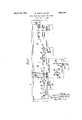
- the figure is a plan view of a sheet production layout arranged in accordance with one embodiment of this invention.
- a preferred form of production layout is shown thatgcomprises a plurality of longitudinally spaced sheets and plate metal working units A, B, C, D, and E, which may be enclosed within the confines of the shop area 9.
- each of the first three of said units A, B, and C is adapted for a hot rolling process.
- the first of these units A is provided with a suitable heating furnace 11 in order that breakdown. plates, or the like,
- the furnace 11 has a conveyor type feed table 12 adjoining one end and a discharge table 13 adjoining the other end thereof.
- a rolling mill 14 which may be operated as 2-high, but will preferably be operated as 3-high. Power for rotating rollers of the mill 14, is obtained through a suitable speed reduction mechanism 16 from a motor 17. Both this motor and thegear mechanism are located in the individual compartment 18.
- the motor may be, and preferably is a variable speed motor.
- the breakdown plates on being heated in the furnace 11 and rolled in the mill 14, are formed into sheets of, say 20 gauge. These 20 gauge sheets are now ready for shearing and are conveyed on the discharge roll table 19 to the shear 20, where they may be cut in two or more pieces and discharged upon a shear table 21. Thence, the sheets are stacked or placed in stock in the area 22, located opposite the space between units A and B, for
- the 20 gauge sheets from t e stock area 22 are carried by a suitable overhead crane'X positioned above the formation of units-on line therewith to a feed table 25 of a heating furnace 26 of unit B. After a proper heating temperature of the sheets has been attained, they are conveyed from the roll table 27 to the mill 28 and rolled into 26 gauge sheets. If sheets of the gauges re-' ferred as examples, are to be rolled in this unit B, four or six sheets may be worked together, by the usual stacking procedure
- the mill 28, preferably of the two-high type has a suitable motivating mechanism designated in its entirety by 29, similar to 16, 17 of unit A. As in unit A, the sheets are now stacked in a stock area 30 for cooling, in effect curing, resting and/or storage purposes.
- stresses induced by irregular cooling or by cold working may be gradually relieved by rest, to the benefit of the metal, especially if solutely constant efl'ecton the elastic limit of most metals.
- thermo-electric power that is thought to be the true index of stress, changes rapidly when steel has a heat of about 66 G. Since the temperature of a stack of sheets may approximate this value, it is felt that this is one of the possible explanations of the benefits derived from resting. And, since the metal finally rested before the operation is again repeated, I have produced a remarkably better-product by my method simply through the agency of resting.
- the cooling in itself has a very excellent effect upon the quality ofthe product.
- Tempering taken in its general sense, is accomplished thereby after each hot working or rolling of the product.
- the crystalline structure is better and morethoroughly reduced and refined, and is given more homogeneity; segregation and heterogeneousness are more thoroughly broken up, and the strength of the metal-is ultimately increased.
- the length of time of the rest will depend upon the particular nature of the metal, and in some cases the short resting accomplished by mere cooling may be sufficient.
- unit C may have rolls and suitable heating furnaces somewhat similar to unit B and, of course, the working process of the sheets is carried on in the same manner. After the sheets have been rolled into 30 gauge thickness, they are placed in the stock area 38.
- a unit C may be installed to meet future requirements. This unit C is illustrated to bring out the possibility of the addition. of parallel units to any or all of the three hot rolling units A, B, and C in order to meet future demands or excessive demands for a given gauge sheet.
- the so-called future units may be driven by a power shaft common to its adj acent parallel units or common to those units which have a given work in common.
- any or all of the sheets from the units A, B, C, etc. are trimmed and sheared to length and width in the unit D having a trimmer 40 and a shear 42, and suitable sheet conveyingtables 41, 43 and 44.
- the sheets After passing through this unit D, the sheets may be placed in stock. If it is desirable to cold roll the sheets in order to increase their hardness and improve their surface, they may be run singularly through one or another of the three parallel roll stands 46 of unit E. A motor 47 and its speed reduction gear 48, located in the space 49, furnish power for driving these roll stands. After cold rolling the sheets are ready for annealing and may be subsequently stored or galvanized as desired.
- Each hot rolling unit although its operation is independently and separately controlled in respect to other longitudinally spaced units can be cooperatively and semi: dependently operated withrespect to ad acent and non-adjacent units.
- the advantages derived from the provision of a plurality of longitudinally-spaced, independent, cooperative' units, is at once apparent. -First, each unit, effecting a certain treatment of the sheets or plates, is set off by itself.
- each unit may be entirely independently controlled in respect to an adjacent unit.
- a substantially straight-line spaced-longitudinal positioning or formation of each unit not only adds to the efiiciency of the entire layout, but also permits efiicient independentce of the adjacent, unit, and has the additional advantage that the partially finished sheets are in effect cured or aged in thevarious storage spaces.
- Amill layout which includes a plurality of metal-working units positioned in substantially straight-line spaced longitudinal formation; the first of said units including a heating furnace, a mill, a roll table located between said furnace and said mill, a shear,
- the second of said units including a heating furnace, a mill, and a roll table between said furnace and said mill;
- the third of said units including afurnace, a mill and a roll table between said mill and said furnace;
- each of said three units having an individual v sheet stacking area near its discharge end;
- the fourth of said units including a trimmer furnace plurality and shear having a table therebetween; and, the fifth of said units including a plurality of transversely positioned cold rolls.
- a mill layout which includes a plurality of metal-working units positioned in substantially straight-line spaced-longitudinal formation"; the first of said units including a heating furnace, hot rolls and a conveyor table therebetween, a shear and a conveyor table between said rolls and said shear; the second of said units including a heating furnace, a mill and a roll table between said furnace and said mill; the third of said units including a furnace, a mill and a roll table between said mill and said furnace; each of said three units having an individual storage area.
- the fourth of said units including a trimmer and a shear having a conveyor table therebetween;
- the fifth of said units including a alurality of transversely aXled cold rolls, said rolls being adapted to be driven by a single motivating mechanism.
- a mill layout which includes a plurality of metal-working units positioned in substantially straight-line spaced-longitudinal formation; the first of said units including a heating furnace, a mill, a roll table located between said furnace and said mill, a shear, and a rolltable between said mill and said shear; the second of said units including a heating furnace, a mill and a roll table located between said furnace and said mill; the third of said units including a furnace, a mill and a conveyor table therebetween, the Whole being constructed and arranged to permit a plurality of like units to be transversely positioned adjacent each other.
- a mill layout which includes a plurality of metal working units positioned in substantially straight-line spaced-longitudinal formation: the first of said units including a heating furnace, a mill, a roll table located between said furnace and said mill, a shear, a roll table between said mill and said shear; the second of said units including a heating-furnace, a mill and a roll table between said furnace and said mill; the third of said units including a furnace, a roll table and a conveyor table therebetween, the whole being constructed and arranged to permit a of similar units to be transversely positioned adjacent each other; each of said three units having an individual stock area near its discharge end; the fourth of said units including a trimmer and shear having a table therebetween; and the fifth of said units including a plurality of transversely positioned cold rolls.
- a mill layout which includes a plurality'of metal working units positioned in substantially straight-line spaced-longitudinal formation; the first of said units including a heating furnace, a mill, a shear, and suitable tables therefor; the second of said units ineluding a heating furnace, a mill, and suitable tables therefor; the third of said units including a furnace, a mill, and suitable tables therefor; each of said three units having an individual sheet stacking area near its discharge end; the fourth of said units in-- cluding a trimmer and a shear having a suitable table therebetween.
- a mill layout which includes a plurality of metal working units positioned in substantially straight-line spaced-longitudinal formation; the first of said units including a heating furnace, a mill, a roll table located between said furnace and said mill, a shear, and roll table located between said mill and said shear; the second of said units including a heating furnace, a mill, and a roll table between said furnace and said mill; the third of said units including a furnace, a mill, and a roll table between said mill and said furnace; each of said three units having an individual sheet stacking area near its discharge end, each of said areas having a trans- 7 each of said three units having an individual second of said units including a trimmer, a
- a mill layout which includes a plurality of metal working units positionedin substantially straight-line spaced-longitudinal formation; the first of said units including a feed table, a heatin furnace, a discharge table, a mill, a roll ta le, a shear, and a shear table; the second 0f sa1d units including a feed table, a heating furnace, a roll table, and a mill; each of said units having an individual sheet stacking area near its discharge end and the length thereof corresponding substantially to the spacing between said units; and a third unit including a plurality of transversely positioned cold rolls.
- a 'mill layout which includes a plurality of metal working units positioned in substantialy straight-line spaced-longitudinal formation; the first of said units including a feed table, a heating furnace, a discharge table, a mill, a roll table, a shear, and
- each of said two units having an individual sheet stacking area near its discharge end whose length corresponds to the spacing between adjacent units; and a third of said units including a plurality of transversely positioned cold rolls.
- a mill layout which includes a plurality of metal working units positioned in substantially straight-line spaced-longitudinal formation; the first of said units including a heating furnace, hot rolls, a shear, and suitable conveyor feed and discharge tables therefor; the second of said units including a heating furnace, a plurality of transversely positioned mills, and suitable tables therefor, the third of said units including a trimmer, a shear, and suitable tables therefor; the fourth of said units including a plurality of transversely positioned cold rolls provided with a common motivatiliguniu 11.
- a mill layout which includes a pluv rality of metal working units positioned in substantially straight-line and spaced-longitudinal formation; the first of said units including a heating furnace, a mill, a roll table located between said furnace and said mill, a
- the second of said units including a heating furnace, a mill, and a roll table between said furnace and said mill;
- the third of said units including a furnace, a roll table and a conveyor therebetween, the whole being constructed and arranged to permit a plurality of similar u'nits'to be transversely positioned with respect to each other and to be motivated by a common mechanism; each of said three units having an individual sheet stacking area near its discharge end whose length corresponds to the stacking between adjacent of said units the fourth of said un1ts including attrimmer and a shear, and suitable tables therefor; the fifth of said units including suitable cold rolls; and a conveying mechanism disposed above and on line with said metal working units for carrying metal to and from said units as well as to and from said stacking areas.
Landscapes
- Engineering & Computer Science (AREA)
- Mechanical Engineering (AREA)
- Metal Rolling (AREA)
Description
M r 1932. w. WORTHINGTON MILL PRODUCTION METHOD AND LAYOUT Filed Dec. 13. 1929 Patented Mar. 29, 1932 PATENT OFFICE WARREN WORTHINGTON, OF PITTSBURGH, PENNSYLVANIA MILL PRODUCTION METHOD AND LAYOUT Application filed December 13, 1929. Serial No. 413,878.
made to overcome certain of those which seem to be the most outstanding. But, previous to the present inventiomthe steel and like, al-
lied industries have been working under a handicap.
This handicap arises from the fact that although it is well known to the industrythat the products of the present sheet mill methods arenot the efficient summation of work, labor, material, and treatment involved, yet no one has been able to determine a factor, which, if met, would allow the production of a higher quality finished product, and do so at a greatly increased overall efficiency.
" As explained above the problemswhich arise in the steel and allied industries are many and complex. The ehiciency of methods and layouts employed isordinarilyevidenced by the high cost of production, the number of rejected pieces, or the quality of the finished product; but, until the present invention, it was not traced to lack of flexibility or lack of cooperative independence between units 9 producing sheets and plates of varied characteristics, especially where those sheets have certain characteristics in common with those produced by adjacent units, for instance, sheets or plates of the same width, gauge, or
' of-the same grade of steel.
A common measure of rolling mill difficulties is scaled on the proportion of time lost during the operation of the mill; that is, the seriousness of a ditficulty is estimated in proportion to the delay it causes in the operation of the mill, rather than in the loss of a small amount of material or of a part of the mill itself. Thus, the solution of the proby lem which arises out of shutdowns and the resultant evil effects is all important to the industry. Spare motors, engines, and the substitution of new parts, rather than repairing the old, are examples of how far the industry is willing to go in order to lessen prow duction delays and mixups.
A layout, such as now commonly em loyed in steel mill practice consists of a plura ity of mills, each mill having a cooperating heating furnace and being transversely located wit-h respect to the other mills. Continuous conveyors are sometimes positioned between adjacent mills and are connected between the rolls of one mill and the furnace of another mill. It can be readily conceived just what effect the breaking of a part in one mill or the need 'of replacement of the rolls of another mill will have upon production of the entire layout. The forming operation for sheets of a given gauge is essentially a series of cooperative steps in which each unit involved, is absolutely dependent upon other units for its supply of partly finished sheets; thus, a shutdown of any unit involved in the operations will upset the entire conformity'of pro,-' duction layout. For these reasons an unusu- '7 ally large demand for one particular gauge of sheet-will also cause difficulties. It is often necessary to shut down anumber of units under such a condition of production, and this of course cuts down production efiiciency.
Another disadvantage in the present mill layout rests upon the number of high priced men that must be employed in order; that the various apparatus may be efiectively operated. Since the heating furnaces of each .80 traverse layout are directly opposite each other, a veritable inferno is created, reducing the number of working hours for each man and, of course, increasing the wage scale.
Due to the interdependence of the units of present day mill layouts, the mills of each unit cannot be varied as to speed with respect to adjacent units. Speed variation is desirable in order to meet the requirements of different thicknesses, grades, quality, and quantity of sheeting. Then too, the control of speed is desirable in order to obtain the requisite flexibility where various rolling temperatures are necessary or are employcd, and also because of the variation in r the number of passes, and the reduction necessary in the pass of each unit. At first glance it would seem that the temperature of the sheets or plates being passed through one unit of'a plurality of speed dependent units could be independently varied. But, this is not wholly true, for, there is a temperature corresponding to a given speed that will produce most efficient results. This can be visualized, since with an increase of speed there will be an increase of frictional heat generated, and since the time consumed in the passes effects the heat loss therein, and frictional heating efiects are further increased with an increase of thickness reduction in a given pass. Then too, it is common in the industry to have an unexpected demand for certain gauge sheets, and a consequent lesser demand for other gauge sheets.
And it has been one object of this invention to disc-over a factor which will eliminate the cause of a large proportion of the inefliciencies of present day rolling methods, and to provide a solution for this cause.
Another object of this invention has been to provide a production mill method and layout whereby the heat and speed of the sheets passing through, the rolls of adjacent mills can be independently controlled in respect to other mill units.
Another object of this invention has been to provide a production method and layout whereby the heating furnace of each of the adjacent units will be separated from other furnaces by the length of the rolling, or of the rolling and shearing apparatus.
A further object of this invention has been to provide a production layout, each unit of which can be made to continuously operate and produce a quantity of sheets or the like proportionate to the demand for a given ,size without lessening the quantity of production of other size sheets.
A further object of this invention has been to provide a mill production method whereby each unit thereof will have cooperative independence.
Other objects of this invention will appear to those skilled in the art from the following description taken in conjunction with the accompanying drawing, in which:
The figure is a plan view of a sheet production layout arranged in accordance with one embodiment of this invention.
In the drawing, a preferred form of production layout is shown thatgcomprises a plurality of longitudinally spaced sheets and plate metal working units A, B, C, D, and E, which may be enclosed within the confines of the shop area 9.
In order that sheets of desired gauge may be attained, each of the first three of said units A, B, and C is adapted for a hot rolling process. The first of these units A, is provided with a suitable heating furnace 11 in order that breakdown. plates, or the like,
may be prepared for rolling. The furnace 11, has a conveyor type feed table 12 adjoining one end and a discharge table 13 adjoining the other end thereof.
For purposes of illustration, the sheets- To reduce breakdown plates or the like, to
sheets of suitable size, say 20 gauge, a rolling mill 14 is provided which may be operated as 2-high, but will preferably be operated as 3-high. Power for rotating rollers of the mill 14, is obtained through a suitable speed reduction mechanism 16 from a motor 17. Both this motor and thegear mechanism are located in the individual compartment 18. The motor may be, and preferably is a variable speed motor.
In order that plates from the heating furnace 11 will be continuousl fed to the mill 14, and that completely rolle sheets will be fed to a shearing mechanism 20, roll tables 19 and 21 are provided.
' The breakdown plates on being heated in the furnace 11 and rolled in the mill 14, are formed into sheets of, say 20 gauge. These 20 gauge sheets are now ready for shearing and are conveyed on the discharge roll table 19 to the shear 20, where they may be cut in two or more pieces and discharged upon a shear table 21. Thence, the sheets are stacked or placed in stock in the area 22, located opposite the space between units A and B, for
cooling, resting, and/or curing.
If sheets of lesser thickness, say 26 gau are required, the 20 gauge sheets from t e stock area 22 are carried by a suitable overhead crane'X positioned above the formation of units-on line therewith to a feed table 25 of a heating furnace 26 of unit B. After a proper heating temperature of the sheets has been attained, they are conveyed from the roll table 27 to the mill 28 and rolled into 26 gauge sheets. If sheets of the gauges re-' ferred as examples, are to be rolled in this unit B, four or six sheets may be worked together, by the usual stacking procedure The mill 28, preferably of the two-high type, has a suitable motivating mechanism designated in its entirety by 29, similar to 16, 17 of unit A. As in unit A, the sheets are now stacked in a stock area 30 for cooling, in effect curing, resting and/or storage purposes.
In order that those sln'lled in the art may more readily understand just why I cool and/or rest the metal sheets after one working operation and before another, a brief explanation will follow. Although resting is generally known to the metal working indus try, yet many of the results therefrom and the value thereof, are not generally known. The tensile strength and the elastic limit of iron that has been distorted beyond its elastic limit will increase for a long time, probably for many years. Further, internal is first heated, then hot worked, cooled, and
stresses induced by irregular cooling or by cold working may be gradually relieved by rest, to the benefit of the metal, especially if solutely constant efl'ecton the elastic limit of most metals.
The thermo-electric power that is thought to be the true index of stress, changes rapidly when steel has a heat of about 66 G. Since the temperature of a stack of sheets may approximate this value, it is felt that this is one of the possible explanations of the benefits derived from resting. And, since the metal finally rested before the operation is again repeated, I have produced a remarkably better-product by my method simply through the agency of resting.
Further, the cooling in itself has a very excellent effect upon the quality ofthe product.
Tempering, taken in its general sense, is accomplished thereby after each hot working or rolling of the product. The crystalline structure is better and morethoroughly reduced and refined, and is given more homogeneity; segregation and heterogeneousness are more thoroughly broken up, and the strength of the metal-is ultimately increased. But, I have added these two methods together, namely, cooling and resting, and by the combination thereof have further increased the quality of the product.
sequent reworking.
The length of time of the rest will depend upon the particular nature of the metal, and in some cases the short resting accomplished by mere cooling may be sufficient.
Since a large number of sheets are normally piled or stacked in a given stock area, not
of six or eight sheets of 26 gauge may be hot rolled at one time in unit C. The unit C may have rolls and suitable heating furnaces somewhat similar to unit B and, of course, the working process of the sheets is carried on in the same manner. After the sheets have been rolled into 30 gauge thickness, they are placed in the stock area 38. As shown in the drawing, parallel, and, transversely opposite to this unit C, a unit C may be installed to meet future requirements. This unit C is illustrated to bring out the possibility of the addition. of parallel units to any or all of the three hot rolling units A, B, and C in order to meet future demands or excessive demands for a given gauge sheet. As seen, the so-called future units may be driven by a power shaft common to its adj acent parallel units or common to those units which have a given work in common. Unit Chas a motivating unit and mechanism 37 similar to that of units A and B.
Any or all of the sheets from the units A, B, C, etc., are trimmed and sheared to length and width in the unit D having a trimmer 40 and a shear 42, and suitable sheet conveyingtables 41, 43 and 44. After passing through this unit D, the sheets may be placed in stock. If it is desirable to cold roll the sheets in order to increase their hardness and improve their surface, they may be run singularly through one or another of the three parallel roll stands 46 of unit E. A motor 47 and its speed reduction gear 48, located in the space 49, furnish power for driving these roll stands. After cold rolling the sheets are ready for annealing and may be subsequently stored or galvanized as desired.
The layout shown as an embodiment of my.
only are the sheets given an opportunity for inventiomis adapted to meet the demands for rest, but also, are somewhat or mildly annealed during thatperiod by reason of the heat held in by the large quantityof metal present and the continual adding of new sheets just after the hot rolling operations. The applicant stacks the newly added sheets so that they will impart heat to the old sheets, and so that in addition, the old or rest-treated sheets can readily be first removed for a sub This explanation has merely been added to more clearly show just how the operation is conducted during the resting period. That is, by this stacking method the value of the resting period is greatly enhanced since a very slight heat is maintained atall times. As a result, a combined annealing and resting action is produced upon the sheets thereby very materially increasing their strength and grain qualidifferent size sheets, and it is also apparent that a temporary shutdown of one hot rolling unit will not affect or delay the operation of other units. Sheets from stock areas 22, 30, and 38 can be sheared and trimmed and if desired cold rolled and annealed to meet the demands of those sizes. If there is a greater demand, for instance, for 26 gauge sheets, and for 30 gauge sheets, then parallel units may be added to the hot rolling units A and B, in a manner similar to that shown for unit .0 in the form of unit 0'.
Each hot rolling unit, although its operation is independently and separately controlled in respect to other longitudinally spaced units can be cooperatively and semi: dependently operated withrespect to ad acent and non-adjacent units. The advantages derived from the provision of a plurality of longitudinally-spaced, independent, cooperative' units, is at once apparent. -First, each unit, effecting a certain treatment of the sheets or plates, is set off by itself.
Thus, the rollfspeed, the temperature of too,
the material being treated, and the thickness reduction between the passes of each unit may be entirely independently controlled in respect to an adjacent unit. A substantially straight-line spaced-longitudinal positioning or formation of each unit not only adds to the efiiciency of the entire layout, but also permits efiicient independentce of the adjacent, unit, and has the additional advantage that the partially finished sheets are in effect cured or aged in thevarious storage spaces.
Confusion is eliminated, and future demands for given size sheets are readily taken care of by adding additional units of similar purpose in transverse and parallel positioning with respect to the original unit. Then a saving in power may be effected by axling future mills to the old mills as shown in connection with units C and C. The stock areas 22, 30, and 38 have been located opposite the space between adjacent units so as to permit the sheet stacking and charging crews to operate efficiently; and, if desired, a conveyor may be installed between units to meet the demands of a given situav tion. This layout is productive of quick repairs, for the men are given more room in which to work, and the parts are more readily accessible.
One of the great advantages of the layout lies in the fact that the sheetsor other products of production will always move in the same direction, no matter What their size or gauge, degree or nature of treatment. In other words. the crane X when carrying sheets or plates need only travel from left to right in the layout shown in the drawing. saving in time, labor, and expense that arise from mixups andcomplicated situations, will necessarily follow.
While I have described but one embodiment ofthis invention, it will be apparent that many changes, modifications, substitutions, additions, and omissions, or combinations thereof may be made in this device without departing from the spirit and scope of the invention as indicated in the appended claims.
What I claim as new and desire'to secure byLetters Patent is: i
1. Amill layout which includes a plurality of metal-working units positioned in substantially straight-line spaced longitudinal formation; the first of said units including a heating furnace, a mill, a roll table located between said furnace and said mill, a shear,
a roll table located between said mill and said shear; the second of said units including a heating furnace, a mill, and a roll table between said furnace and said mill; the third of said units including afurnace, a mill and a roll table between said mill and said furnace;
each of said three units having an individual v sheet stacking area near its discharge end;
the fourth of said units including a trimmer furnace plurality and shear having a table therebetween; and, the fifth of said units including a plurality of transversely positioned cold rolls.
' 2. A mill layout which includes a plurality of metal-working units positioned in substantially straight-line spaced-longitudinal formation"; the first of said units including a heating furnace, hot rolls and a conveyor table therebetween, a shear and a conveyor table between said rolls and said shear; the second of said units including a heating furnace, a mill and a roll table between said furnace and said mill; the third of said units including a furnace, a mill and a roll table between said mill and said furnace; each of said three units having an individual storage area. opposite each space between units, and having suitable motivating mechanisms; the fourth of said units including a trimmer and a shear having a conveyor table therebetween; the fifth of said units including a alurality of transversely aXled cold rolls, said rolls being adapted to be driven by a single motivating mechanism.
3. A mill layout which includes a plurality of metal-working units positioned in substantially straight-line spaced-longitudinal formation; the first of said units including a heating furnace, a mill, a roll table located between said furnace and said mill, a shear, and a rolltable between said mill and said shear; the second of said units including a heating furnace, a mill and a roll table located between said furnace and said mill; the third of said units including a furnace, a mill and a conveyor table therebetween, the Whole being constructed and arranged to permit a plurality of like units to be transversely positioned adjacent each other.
4:. A mill layout which includes a plurality of metal working units positioned in substantially straight-line spaced-longitudinal formation: the first of said units including a heating furnace, a mill, a roll table located between said furnace and said mill, a shear, a roll table between said mill and said shear; the second of said units including a heating-furnace, a mill and a roll table between said furnace and said mill; the third of said units including a furnace, a roll table and a conveyor table therebetween, the whole being constructed and arranged to permit a of similar units to be transversely positioned adjacent each other; each of said three units having an individual stock area near its discharge end; the fourth of said units including a trimmer and shear having a table therebetween; and the fifth of said units including a plurality of transversely positioned cold rolls. v
5. A mill layout which includes a plurality'of metal working units positioned in substantially straight-line spaced-longitudinal formation; the first of said units including a heating furnace, a mill, a shear, and suitable tables therefor; the second of said units ineluding a heating furnace, a mill, and suitable tables therefor; the third of said units including a furnace, a mill, and suitable tables therefor; each of said three units having an individual sheet stacking area near its discharge end; the fourth of said units in-- cluding a trimmer and a shear having a suitable table therebetween.
6. A mill layout which includes a plurality of metal working units positioned in substantially straight-line spaced-longitudinal formation; the first of said units including a heating furnace, a mill, a roll table located between said furnace and said mill, a shear, and roll table located between said mill and said shear; the second of said units including a heating furnace, a mill, and a roll table between said furnace and said mill; the third of said units including a furnace, a mill, and a roll table between said mill and said furnace; each of said three units having an individual sheet stacking area near its discharge end, each of said areas having a trans- 7 each of said three units having an individual second of said units including a trimmer, a
sheet stacking area near its discharge end, the length of said area corresponding to the spacing between each adjacent unit; and the fourth of said units including a cold roll.
8. A mill layout which includes a plurality of metal working units positionedin substantially straight-line spaced-longitudinal formation; the first of said units including a feed table, a heatin furnace, a discharge table, a mill, a roll ta le, a shear, and a shear table; the second 0f sa1d units including a feed table, a heating furnace, a roll table, and a mill; each of said units having an individual sheet stacking area near its discharge end and the length thereof corresponding substantially to the spacing between said units; and a third unit including a plurality of transversely positioned cold rolls.
9. A 'mill layout which includes a plurality of metal working units positioned in substantialy straight-line spaced-longitudinal formation; the first of said units including a feed table, a heating furnace, a discharge table, a mill, a roll table, a shear, and
a shear table in the order mentioned; the
shear, and a suitable table therebetwen; each of said two units having an individual sheet stacking area near its discharge end whose length corresponds to the spacing between adjacent units; and a third of said units including a plurality of transversely positioned cold rolls.
10. A mill layout which includes a plurality of metal working units positioned in substantially straight-line spaced-longitudinal formation; the first of said units including a heating furnace, hot rolls, a shear, and suitable conveyor feed and discharge tables therefor; the second of said units including a heating furnace, a plurality of transversely positioned mills, and suitable tables therefor, the third of said units including a trimmer, a shear, and suitable tables therefor; the fourth of said units including a plurality of transversely positioned cold rolls provided with a common motivatiliguniu 11. In a mill layout which includes a pluv rality of metal working units positioned in substantially straight-line and spaced-longitudinal formation; the first of said units including a heating furnace, a mill, a roll table located between said furnace and said mill, a
shear and a roll table between said mill and said shear; the second of said units including a heating furnace, a mill, and a roll table between said furnace and said mill; the third of said units including a furnace, a roll table and a conveyor therebetween, the whole being constructed and arranged to permit a plurality of similar u'nits'to be transversely positioned with respect to each other and to be motivated by a common mechanism; each of said three units having an individual sheet stacking area near its discharge end whose length corresponds to the stacking between adjacent of said units the fourth of said un1ts including attrimmer and a shear, and suitable tables therefor; the fifth of said units including suitable cold rolls; and a conveying mechanism disposed above and on line with said metal working units for carrying metal to and from said units as well as to and from said stacking areas.
In testimony whereof, I have hereunto subscribed my name this 11th day of December, 1929.
WARREN WORTHINGTON.
Priority Applications (1)
| Application Number | Priority Date | Filing Date | Title |
|---|---|---|---|
| US413878A US1851340A (en) | 1929-12-13 | 1929-12-13 | Mill production method and layout |
Applications Claiming Priority (1)
| Application Number | Priority Date | Filing Date | Title |
|---|---|---|---|
| US413878A US1851340A (en) | 1929-12-13 | 1929-12-13 | Mill production method and layout |
Publications (1)
| Publication Number | Publication Date |
|---|---|
| US1851340A true US1851340A (en) | 1932-03-29 |
Family
ID=23639040
Family Applications (1)
| Application Number | Title | Priority Date | Filing Date |
|---|---|---|---|
| US413878A Expired - Lifetime US1851340A (en) | 1929-12-13 | 1929-12-13 | Mill production method and layout |
Country Status (1)
| Country | Link |
|---|---|
| US (1) | US1851340A (en) |
-
1929
- 1929-12-13 US US413878A patent/US1851340A/en not_active Expired - Lifetime
Similar Documents
| Publication | Publication Date | Title |
|---|---|---|
| US4308739A (en) | Method for modernizing a hot strip mill | |
| US1932750A (en) | Rolling mill | |
| US1851340A (en) | Mill production method and layout | |
| US1771688A (en) | Method and apparatus for manufacturing metal sheets from ingots | |
| EP4408595B1 (en) | System and method for producing flat rolled products | |
| US1839789A (en) | Rolling sheets | |
| DE102022208767A1 (en) | Plant and method for manufacturing rolled products | |
| US1966554A (en) | Rolling mill and method of rolling | |
| US865055A (en) | Process of rolling sheet metal. | |
| US2002266A (en) | Method of rolling strip material | |
| US1895299A (en) | Rolling sheet metal | |
| US1842220A (en) | Sheet metal rolling process | |
| US1987876A (en) | Merchant mill layout | |
| US1852271A (en) | Process of rolling sheets | |
| US1108213A (en) | Art of making metal sheets. | |
| US1525456A (en) | Method of rolling zinc slabs | |
| US419008A (en) | Rolling-mill plant | |
| US1581039A (en) | Process in rolling hot metal | |
| US1477616A (en) | Rolling mill | |
| US654100A (en) | Apparatus for rolling flanged sections. | |
| USRE18413E (en) | of middletown | |
| US418371A (en) | Mode of manufacturing sheet metal | |
| US733085A (en) | Method of manufacturing railway-rail-joint plates. | |
| US1786834A (en) | Rolling metal | |
| US1910648A (en) | Rolling of thin gauge sheet metal |