US185134A - Improvement in fluid-regulators - Google Patents
Improvement in fluid-regulators Download PDFInfo
- Publication number
- US185134A US185134A US185134DA US185134A US 185134 A US185134 A US 185134A US 185134D A US185134D A US 185134DA US 185134 A US185134 A US 185134A
- Authority
- US
- United States
- Prior art keywords
- chamber
- fluid
- reservoir
- valve
- regulators
- Prior art date
- Legal status (The legal status is an assumption and is not a legal conclusion. Google has not performed a legal analysis and makes no representation as to the accuracy of the status listed.)
- Expired - Lifetime
Links
- 239000012530 fluid Substances 0.000 description 26
- 230000001105 regulatory Effects 0.000 description 6
- 239000007788 liquid Substances 0.000 description 4
- 239000004215 Carbon black (E152) Substances 0.000 description 2
- 239000007799 cork Substances 0.000 description 2
- 150000002430 hydrocarbons Chemical class 0.000 description 2
- 239000000463 material Substances 0.000 description 2
Images
Classifications
-
- A—HUMAN NECESSITIES
- A47—FURNITURE; DOMESTIC ARTICLES OR APPLIANCES; COFFEE MILLS; SPICE MILLS; SUCTION CLEANERS IN GENERAL
- A47L—DOMESTIC WASHING OR CLEANING; SUCTION CLEANERS IN GENERAL
- A47L13/00—Implements for cleaning floors, carpets, furniture, walls, or wall coverings
- A47L13/02—Scraping
- A47L13/08—Scraping with scraping blades
-
- Y—GENERAL TAGGING OF NEW TECHNOLOGICAL DEVELOPMENTS; GENERAL TAGGING OF CROSS-SECTIONAL TECHNOLOGIES SPANNING OVER SEVERAL SECTIONS OF THE IPC; TECHNICAL SUBJECTS COVERED BY FORMER USPC CROSS-REFERENCE ART COLLECTIONS [XRACs] AND DIGESTS
- Y10—TECHNICAL SUBJECTS COVERED BY FORMER USPC
- Y10T—TECHNICAL SUBJECTS COVERED BY FORMER US CLASSIFICATION
- Y10T137/00—Fluid handling
- Y10T137/7287—Liquid level responsive or maintaining systems
- Y10T137/7358—By float controlled valve
- Y10T137/7423—Rectilinearly traveling float
Definitions
- My invention relates to a means for regulating and indicating the flow of fluids through a reservoir. It is designed more particularly to be used in connection with a hydrocarbon or vapor burner; but it may be employed as an independent measurer and indicator for fluids of any description.
- the invention consists in the connection, with a reservoir for holding fluids, of a smaller reservoir or chamber. which is kept supplied with fluid to a certain required amount, and when fullysupplied the flow of fluid is stopped by means of a vaive operated by a float, to close the opening through which the fluid passes.
- the fluid in the secondary reservoir or chamber passes to the burner, and, as it is consumed, the supply decreases, and, as the float falls, the valve is caused to open, to admit of a further supply, thus causing a steady and limited though sufficient feed to the burner, and insuring safety and reliability of operation.
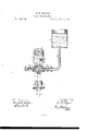
- the accompanying drawing represents a vertical Section of an apparatus embodying my invention, and also a view of the support for the regulating-chamber.
- A represents a reservoir, which may be of any desired size or form, and is provided with a delivery-pipe, B, connected at its lower end with a section of pipe, N. provided with a cock, 0, for shutting 0d the flow of oilfrorn the reservoir when necessary.
- the pipe N is connected to a T-piece or support, K, which is cast in one piece, and is provided with the separate passages b and c. It has also'a screwthreaded hollow projection, m, on its under side, for attaching the support to a stand.
- a valvechamber, D which connects with the passage 1) in the T-piece K.
- valve-chamber D In the upper end of the valve-chamber D is an opening, through which passes the oil or fluid into the chamber H.
- E represents a ball-valve, which moves freely up and down in chamber D, and is connected with a rod, E, that passes through the opening in the upper part of valve-chamber D, and through a float, G, of cork or other suitable material, to which it is attached, so as to move with the'same.
- the rod E extends upward through the cover of chamber E, and serves as an indicator to denote the height of the liquid in chamber H.
- the chamber H is provided with an outlet, I, connecting with the passage 0 in the T-piece or support K that leads to the burner.
- The-height of the liquid in chamber H is to be governed by the supply of fluid required for the burner, and when a sufficient quantity has entered chamber H from the reservoir A, the ball-valve E, being raised by the float, closes the opening in the upper part of valve-chamber D, and stops the flow of fluid in the chamber H. As the fluid passes out through the exit-pipe I to supply the burner, the float falls, and, the valve being opened, a further supply is furnished to chamber H.
- the burner is thus always kept Supplied with the requisite amount of fluid, and no more is allowed to pass than is actually required, and all danger and inconvenience incident to an over-supply are obviated, and the utmost safety and ease of operation are socured.
- the T-piece or support K provided with the indirect passages b and a, as and for the purposeset forth.
Description
E. F. ROGERS.
FLUID REGULATOR. No.185,134. Patented Dec. 5,1876.
WITNESSES INVENTU wv w a EDWARD-F. ROGERS, OF CHELSEA, MASSACHUSETTS.
IMPROVEMENT IN FLUID-REGULATORS.
Specification forming part of Letters Patent No. 185, l 34, dated December 5, 1876 application filed October 25, 1876.
To all whom it may concern:
Be it known that I, EDWARD F. ROGERS, of Chelsea, in the county of Sufl'olk and State of Massachusetts, have invented an Improved Device for Regulating and Indicating the Flow of Fluids, of which the following is a specification:
My invention relates to a means for regulating and indicating the flow of fluids through a reservoir. It is designed more particularly to be used in connection with a hydrocarbon or vapor burner; but it may be employed as an independent measurer and indicator for fluids of any description.
The invention consists in the connection, with a reservoir for holding fluids, of a smaller reservoir or chamber. which is kept supplied with fluid to a certain required amount, and when fullysupplied the flow of fluid is stopped by means of a vaive operated by a float, to close the opening through which the fluid passes. V
The fluid in the secondary reservoir or chamber passes to the burner, and, as it is consumed, the supply decreases, and, as the float falls, the valve is caused to open, to admit of a further supply, thus causing a steady and limited though sufficient feed to the burner, and insuring safety and reliability of operation.
The accompanying drawing represents a vertical Section of an apparatus embodying my invention, and also a view of the support for the regulating-chamber.
A represents a reservoir, which may be of any desired size or form, and is provided with a delivery-pipe, B, connected at its lower end with a section of pipe, N. provided with a cock, 0, for shutting 0d the flow of oilfrorn the reservoir when necessary. The pipe N is connected to a T-piece or support, K, which is cast in one piece, and is provided with the separate passages b and c. It has also'a screwthreaded hollow projection, m, on its under side, for attaching the support to a stand. In the bottom of the reservoir or chamber H is a valvechamber, D, which connects with the passage 1) in the T-piece K. In the upper end of the valve-chamber D is an opening, through which passes the oil or fluid into the chamber H. E represents a ball-valve, which moves freely up and down in chamber D, and is connected with a rod, E, that passes through the opening in the upper part of valve-chamber D, and through a float, G, of cork or other suitable material, to which it is attached, so as to move with the'same. The rod E extends upward through the cover of chamber E, and serves as an indicator to denote the height of the liquid in chamber H. The chamber H is provided with an outlet, I, connecting with the passage 0 in the T-piece or support K that leads to the burner.
The-height of the liquid in chamber H is to be governed by the supply of fluid required for the burner, and when a sufficient quantity has entered chamber H from the reservoir A, the ball-valve E, being raised by the float, closes the opening in the upper part of valve-chamber D, and stops the flow of fluid in the chamber H. As the fluid passes out through the exit-pipe I to supply the burner, the float falls, and, the valve being opened, a further supply is furnished to chamber H.
The burner is thus always kept Supplied with the requisite amount of fluid, and no more is allowed to pass than is actually required, and all danger and inconvenience incident to an over-supply are obviated, and the utmost safety and ease of operation are socured.
What I claim as my invention, and desire to secure by Letters Patent, is-
l. The combination of the elevated reservoir and a chamber communicating through its lower end with the reservoir and with an outlet,'said chamber carrying a float, and having a valve-seat adapted to a valve arranged below the seat, and regulating the inward upward flow of the oil, as specified.
2. In combination with the chamber A, the T-piece or support K, provided with the indirect passages b and a, as and for the purposeset forth.
In testimony whereof I have signed my name to this specification in the presence of two subscribing witnesses.
E. F. ROGERS.
Witnesses:
J. H. ADAMS, EDGAR E. MANN.
Publications (1)
| Publication Number | Publication Date |
|---|---|
| US185134A true US185134A (en) | 1876-12-05 |
Family
ID=2254539
Family Applications (1)
| Application Number | Title | Priority Date | Filing Date |
|---|---|---|---|
| US185134D Expired - Lifetime US185134A (en) | Improvement in fluid-regulators |
Country Status (1)
| Country | Link |
|---|---|
| US (1) | US185134A (en) |
Cited By (1)
| Publication number | Priority date | Publication date | Assignee | Title |
|---|---|---|---|---|
| US20090093728A1 (en) * | 2007-10-05 | 2009-04-09 | Searete Llc, A Limited Liability Corporation Of The State Of Delaware | Vasculature and lymphatic system imaging and ablation associated with a reservoir |
-
0
- US US185134D patent/US185134A/en not_active Expired - Lifetime
Cited By (1)
| Publication number | Priority date | Publication date | Assignee | Title |
|---|---|---|---|---|
| US20090093728A1 (en) * | 2007-10-05 | 2009-04-09 | Searete Llc, A Limited Liability Corporation Of The State Of Delaware | Vasculature and lymphatic system imaging and ablation associated with a reservoir |
Similar Documents
| Publication | Publication Date | Title |
|---|---|---|
| US185134A (en) | Improvement in fluid-regulators | |
| US602598A (en) | Island | |
| US805498A (en) | Automatic safety check-valve. | |
| US674696A (en) | Water-supply valve. | |
| US386043A (en) | Automatic valve | |
| US1146558A (en) | Water-closet tank. | |
| US486398A (en) | Feed-regulating valve | |
| US411875A (en) | Safety-pressure gas-regulator | |
| US80590A (en) | brockington | |
| US485563A (en) | poschinaer | |
| US1202049A (en) | Liquid-measuring apparatus. | |
| US416232A (en) | Apparatus for distributing lighting-fluids to lamps | |
| US742334A (en) | Oil feeding and storing system. | |
| US322407A (en) | Lubricator | |
| US590641A (en) | Water-supply regulator | |
| US191523A (en) | Improvement in tank-valves | |
| US187042A (en) | Improvement in gas-governors | |
| US128492A (en) | Improvement in pressure-regulators for water-pipes | |
| US783386A (en) | Apparatus for charging liquids with gases. | |
| US198657A (en) | Improvement in regulated valves for carbureters | |
| US655378A (en) | Apparatus for charging liquids with gas. | |
| US210141A (en) | Improvement in gas-pressure regulators | |
| US782815A (en) | Soda-fountain. | |
| US584201A (en) | Fluid-pressure regulator | |
| US1225885A (en) | Boiler-feed-water regulator. |