US1851329A - Condenser for refrigerating systems - Google Patents
Condenser for refrigerating systems Download PDFInfo
- Publication number
- US1851329A US1851329A US387965A US38796529A US1851329A US 1851329 A US1851329 A US 1851329A US 387965 A US387965 A US 387965A US 38796529 A US38796529 A US 38796529A US 1851329 A US1851329 A US 1851329A
- Authority
- US
- United States
- Prior art keywords
- condenser
- refrigerant
- heat
- vessel
- water
- Prior art date
- Legal status (The legal status is an assumption and is not a legal conclusion. Google has not performed a legal analysis and makes no representation as to the accuracy of the status listed.)
- Expired - Lifetime
Links
- 239000003507 refrigerant Substances 0.000 description 20
- XLYOFNOQVPJJNP-UHFFFAOYSA-N water Substances O XLYOFNOQVPJJNP-UHFFFAOYSA-N 0.000 description 19
- 239000007788 liquid Substances 0.000 description 7
- RYGMFSIKBFXOCR-UHFFFAOYSA-N Copper Chemical compound [Cu] RYGMFSIKBFXOCR-UHFFFAOYSA-N 0.000 description 3
- 229910052802 copper Inorganic materials 0.000 description 3
- 239000010949 copper Substances 0.000 description 3
- 238000009434 installation Methods 0.000 description 2
- 239000000463 material Substances 0.000 description 2
- 239000002184 metal Substances 0.000 description 2
- 229910052751 metal Inorganic materials 0.000 description 2
- 238000000034 method Methods 0.000 description 2
- 102100035605 Cas scaffolding protein family member 4 Human genes 0.000 description 1
- 101000947106 Homo sapiens Cas scaffolding protein family member 4 Proteins 0.000 description 1
- 230000006835 compression Effects 0.000 description 1
- 238000007906 compression Methods 0.000 description 1
- JHIVVAPYMSGYDF-UHFFFAOYSA-N cyclohexanone Chemical compound O=C1CCCCC1 JHIVVAPYMSGYDF-UHFFFAOYSA-N 0.000 description 1
- 239000000945 filler Substances 0.000 description 1
Images
Classifications
-
- F—MECHANICAL ENGINEERING; LIGHTING; HEATING; WEAPONS; BLASTING
- F25—REFRIGERATION OR COOLING; COMBINED HEATING AND REFRIGERATION SYSTEMS; HEAT PUMP SYSTEMS; MANUFACTURE OR STORAGE OF ICE; LIQUEFACTION SOLIDIFICATION OF GASES
- F25B—REFRIGERATION MACHINES, PLANTS OR SYSTEMS; COMBINED HEATING AND REFRIGERATION SYSTEMS; HEAT PUMP SYSTEMS
- F25B39/00—Evaporators; Condensers
- F25B39/04—Condensers
-
- F—MECHANICAL ENGINEERING; LIGHTING; HEATING; WEAPONS; BLASTING
- F25—REFRIGERATION OR COOLING; COMBINED HEATING AND REFRIGERATION SYSTEMS; HEAT PUMP SYSTEMS; MANUFACTURE OR STORAGE OF ICE; LIQUEFACTION SOLIDIFICATION OF GASES
- F25B—REFRIGERATION MACHINES, PLANTS OR SYSTEMS; COMBINED HEATING AND REFRIGERATION SYSTEMS; HEAT PUMP SYSTEMS
- F25B2339/00—Details of evaporators; Details of condensers
- F25B2339/04—Details of condensers
- F25B2339/047—Water-cooled condensers
Definitions
- This invention relates to condensers
- Theirefrigerant vessel iscontained wholly 0 .withinthe container and part of mechanical refrigerating systems.
- An object of the invention is to materially lessen the cost of'condensers withoutsacrificing heat tra'nsfer efiiciency or Another object of-my'invention ing systems with which neither running Water nor forced draft is required in order to eifi ciently absorb heat from therefrigerant ing intermittently therethirough.
- a further object of the invention is toprovide acondenser for refrigerating systems of the compression type which will function eificiently and 'With a low head pressure.
- the condenser comprlsesa container 10, a
- refrigerant receiving vessel 11 arranged with-- (not shown).
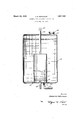
- Atube 1e extends from the upper end of the vessel to the exteriorof the container, and a purgingvalve 15 isassociat ed with the protruding end of such tube.
- the inlet conduit terminates in an enlarged flared v I is to m vide a condenser for mechanical; refrigeratpass I with the liquid, condensed refrigeranhtoa portion 16 acrossthe open'end ofwhichis secured a1fine screen 17.
- the refrigerant containing vessel is formed ofcopper, and is of a size such thatit'will' occupy only a minor portion of I thespace" Within the. container.
- Gas entering the vessel will bubble throughf the condensed'refrigerant and'will be broken f upinto smaller-'bubblesby the screen and'as" I such gas bubbles have a super heat, that is-a heat-greater than the surface liquid refrigerant in the vessehfthe bubbles will yield heat to the liquidland thereby. gasifying someof the liquid while lowering the-incoming "gas temperature; Thus the total volume of gas to be condensed in the-vessel is greater than 1 that issuing from the compressor. It
- the method of condens'ingthe compressedregas comprising moving the compressed gas through and in direct contact with :a of condensed refrigerant and thereby abstracting Eheat therefrom, collectiingthe 'gas adjacent the liquid body after passing .thenethrough, abstracting heat from he "body of condensed refrigerant and the collected gas Witha body of still water.,.and dissipating heat absorbed by the water with natural draft atmosphere.
- the method of condensing compressed refrigerant gas comprising moving the compre ed gas through and in direct contact with a body of condensed refrigerant and thereby abstracting heat therefrom, breaking up the gasbubbles While movingthrough the condensed refrigerant body, collecting the gas adjacent the body after passing therethrough, abstracting heat from the body and the collected gas with still Water, and abstracting the heat absorbed by the Water with natural draft atmosphere.
- a container adapted to hold Water In a mechanical refrigerating condenser, a container adapted to hold Water, a container adapted to hold Water, a container adapted to hold Water, a container adapted to hold Water, a container adapted to hold Water, a container adapted to hold Water, a container adapted to hold Water, a container adapted to hold Water, a container adapted to hold Water, a container adapted to hold Water, a container adapted to hold Water, a container adapted to hold Water, a container adapted to hold Water, a container adapted to hold Water, a container adapted to hold Water, a container adapted to hold Water, a container adapted to hold Water, a container adapted to hold Water, a container adapted to hold Water, a container adapted to hold Water, a container adapted to hold Water, a container adapted to hold Water, a container adapted to hold Water, a container adapted to hold Water, a container adapted to hold Water, a container adapted to hold Water
- a condenser comprising a closed container adapted to hold still Water, a vessel submerged in'the'water in'the container, re-
Landscapes
- Engineering & Computer Science (AREA)
- Physics & Mathematics (AREA)
- Mechanical Engineering (AREA)
- Thermal Sciences (AREA)
- General Engineering & Computer Science (AREA)
- Heat-Exchange Devices With Radiators And Conduit Assemblies (AREA)
Description
CONDENSER FOR REFRIGERATING SYSTEMS Filed Aug. 25, 1929 L/HMEE .5. HEFL UELE.
gguz M Patented at as, we.
imnsfmiznriioenn, or Dari-tori, MroH IGA N ,znssrenonrroiaemnsznsnnrLosLn mm-. f
adding objectionable size. v r y RA'IORIES, Inc, or ,izos'ron; ranssnonusnr'rsgntoonronnrron: org nassecnusnrrs ooivnsusnnron'nnrnie'nn errnesirsirms f1 a Ap ucauoa :filed'Augus'tj 2a, 1929. I i'SCeriaI No; 387,965.
This invention relates to condensers, and
more particularly to condensers forming-a v formed with a filler neck 18 adapted to be closed 'by'the cap 19 which screws thereon.)
.Theirefrigerant vessel iscontained wholly 0 .withinthe container and part of mechanical refrigerating systems.
; Mechanical"refrigerating systems of the domesticltype must be constructedto occupy .a limitedspace and at the sametime transfer heat quickly: during intermittent operation. .As a result it is substantially universal prac ti'se to employ copper as material; because ofits ,pliability andfast heat dissipating qualities, and also to associateeither running water or forced air inthermalcontact with the copper refrigerant container inforder to produ'cethe required heat absorbing efficiency. Copper is expensive, installation and operating costs of running water are high, while air forcing mechanism 1s an added expense, and therefore in order to meet requirements of space and e ficiency a material expense results.- An object of the invention is to materially lessen the cost of'condensers withoutsacrificing heat tra'nsfer efiiciency or Another object of-my'invention ing systems with which neither running Water nor forced draft is required in order to eifi ciently absorb heat from therefrigerant ing intermittently therethirough. i 30 A further object of the invention is toprovide acondenser for refrigerating systems of the compression type which will function eificiently and 'With a low head pressure.
These and other objects of the invention 15 the invention progresses.
will appear as the fol owing descriptionoi,
In the accompanyingdrawings, I haveillustratedin vertical section a. condenser incorporating my invention.
The condenser comprlsesa container 10, a
is closed with respect rectangular envelope adapted to be" secured alongthe, rear Wall of the cabinet' to be refrlgerated sotha't'its position does notmaterially' increasefthe overall dimensionsof the cabinet. The refrigerant containing vessel is formed ofcopper, and is of a size such thatit'will' occupy only a minor portion of I thespace" Within the. container. The 'conthe'conduit 12 from the compressor into the? v .70 tamer-11s filled 'Wlth Water through the neck.-
vessel throughvthescreen 17, and condensed 1 refrigerant leaves the vessel through the'conduit 13min.acondition'for:admissionto the I evaporator 'Theivesseli is partial-1y filled degree such that the screenis'well submerged: I
Gas entering the vesselwill bubble throughf the condensed'refrigerant and'will be broken f upinto smaller-'bubblesby the screen and'as" I such gas bubbles have a super heat, that is-a heat-greater than the surface liquid refrigerant in the vessehfthe bubbles will yield heat to the liquidland thereby. gasifying someof the liquid while lowering the-incoming "gas temperature; Thus the total volume of gas to be condensed in the-vessel is greater than 1 that issuing from the compressor. It
is well. known-that heat flow from acondensinggas withoutsuperheat through metal walls to an absorbing fliquidbccurs about five hundred times ;-as readily as heatlflow. from anon condensing or super heated gasthrough metal walls to alr, and therefore a very. small, amount 0f imetal area or wall'surface w th 2 high gas pressure is required in the vessel con- Obtain heat transfer required. 2Further, the condensercan bezformedsozthat the spaceoc- .cupied zthereby will add very littletothe -overall dimensions of .the cabinetwithwhich it i-SrlQO: be; associated.
struction. Because of this I am able to utilize a large amount of inexpensive low pressure surface for transferring heat from the water to the surrounding air and will obtain the required condensing without water or forced draft-,as the heatcapacity of the water in the container will take care ofthe excess heat flow from the vessel While the apparatus 0 rates intermittently. The surface area of t e container need'be' only sufiicient'to'provide for transferring the average'heat to'be dissipated during hot .weather, astheheat capacity of the Water will take care of the excess rate of heat transfer required during the intermittent compressor'operating periods.
:It will be seen-that the. materialofrthe condenser is inexpensive, thatrno'rrunning water and installations thereof are requiredand that rforced draft is not necessaryin order to Various. changes :can be: madezin the details Of'CODSUfHCtIOD herein described Without de fthe scope of :the claims.
What lclaimris: 1. ,In a .mechariical :nefrigeratingsystem, 11 cQndenSer comprising a "closed container adapted to be filledwith'water, .a vessel in thecontaineradapted to be partially filled with condensed refrigerant, a conduit for admitting compressed refrigerant gas into thevesselibeneath the :liquid refrigerant level, and an outlet conduit through which condensed' refrigerant passes from the vessel. ,2. In a mechanical refrigerating system, the method of condens'ingthe compressedregas comprising moving the compressed gas through and in direct contact with :a of condensed refrigerant and thereby abstracting Eheat therefrom, collectiingthe 'gas adjacent the liquid body after passing .thenethrough, abstracting heat from he "body of condensed refrigerant and the collected gas Witha body of still water.,.and dissipating heat absorbed by the water with natural draft atmosphere.
3. In a mechanical refrigerating system, the method of condensing compressed refrigerant gas comprising moving the compre ed gas through and in direct contact with a body of condensed refrigerant and thereby abstracting heat therefrom, breaking up the gasbubbles While movingthrough the condensed refrigerant body, collecting the gas adjacent the body after passing therethrough, abstracting heat from the body and the collected gas with still Water, and abstracting the heat absorbed by the Water with natural draft atmosphere.
. 4. In a mechanical refrigerating condenser, a container adapted to hold Water, a
the open end of the inlet conduit.
5. In a mechanical refrigerating system, a condenser comprising a closed container adapted to hold still Water, a vessel submerged in'the'water in'the container, re-
"fri'gerant inlet'an d outlet conduits connected with ..the..bottom of said vessel, the outlet end of said inlet conduit terminating in a plurality of apertures, and means for purg- "condenser comprising a closed container adapted to befilled'with-still water, a vessel submerged in the water in-said container, an .inlet conduit extending interiorly of the yessel :for conducting compressed refrigerant into the vessel,"an outletconduit for conducting liquid refrigerant froni'the vessel, said vesselbeing partially filled with condensed refrigerant, and means associated witlrinltconduit below the refrigerant'level :partingfrom the spirit ofthefinvention 'and 7 1 for king p g b b les passing through the liquid refrigerant.
In testimony whereof, I hereunto afli'x my JA 'ES B. REPLO GLE.
Priority Applications (1)
| Application Number | Priority Date | Filing Date | Title |
|---|---|---|---|
| US387965A US1851329A (en) | 1929-08-23 | 1929-08-23 | Condenser for refrigerating systems |
Applications Claiming Priority (1)
| Application Number | Priority Date | Filing Date | Title |
|---|---|---|---|
| US387965A US1851329A (en) | 1929-08-23 | 1929-08-23 | Condenser for refrigerating systems |
Publications (1)
| Publication Number | Publication Date |
|---|---|
| US1851329A true US1851329A (en) | 1932-03-29 |
Family
ID=23532049
Family Applications (1)
| Application Number | Title | Priority Date | Filing Date |
|---|---|---|---|
| US387965A Expired - Lifetime US1851329A (en) | 1929-08-23 | 1929-08-23 | Condenser for refrigerating systems |
Country Status (1)
| Country | Link |
|---|---|
| US (1) | US1851329A (en) |
Cited By (2)
| Publication number | Priority date | Publication date | Assignee | Title |
|---|---|---|---|---|
| US3081068A (en) * | 1959-10-16 | 1963-03-12 | Milleron Norman | Cold trap |
| US11317536B2 (en) * | 2017-12-26 | 2022-04-26 | Sugon Dataenergy(Beijing) Co., Ltd | High-efficiency phase-change condenser of a supercomputer |
-
1929
- 1929-08-23 US US387965A patent/US1851329A/en not_active Expired - Lifetime
Cited By (2)
| Publication number | Priority date | Publication date | Assignee | Title |
|---|---|---|---|---|
| US3081068A (en) * | 1959-10-16 | 1963-03-12 | Milleron Norman | Cold trap |
| US11317536B2 (en) * | 2017-12-26 | 2022-04-26 | Sugon Dataenergy(Beijing) Co., Ltd | High-efficiency phase-change condenser of a supercomputer |
Similar Documents
| Publication | Publication Date | Title |
|---|---|---|
| US3420071A (en) | Suction accumulator | |
| US4242110A (en) | Compressed gas drying apparatus | |
| US1690108A (en) | Heat exchanger | |
| US1851329A (en) | Condenser for refrigerating systems | |
| US3126720A (en) | Absorption refrigerating machine | |
| US2059716A (en) | Liquid level control device | |
| US2384861A (en) | Refrigeration | |
| US2250648A (en) | Refrigerating apparatus | |
| US3681938A (en) | Absorption refrigeration apparatus of the inert gas type | |
| US2134665A (en) | Refrigerating apparatus | |
| US1798824A (en) | Condenser | |
| US1729082A (en) | Refrigerating apparatus | |
| US2367708A (en) | Refrigeration | |
| US2318621A (en) | Refrigeration | |
| US2376505A (en) | Heat exchange apparatus | |
| US2178869A (en) | Absorber for refrigerating systems | |
| US2125727A (en) | Air conditioning apparatus | |
| US3678699A (en) | Absorption | |
| US2730871A (en) | Heat transfer system | |
| US1993129A (en) | Autodefrosting refrigeration apparatus | |
| US2338223A (en) | Refrigeration | |
| US1949126A (en) | Milk cooler | |
| US3174296A (en) | Refrigeration purge system | |
| US1475504A (en) | Refrigerating system | |
| US2813405A (en) | Refrigerant condensing unit |