US1851293A - Window - Google Patents
Window Download PDFInfo
- Publication number
- US1851293A US1851293A US445020A US44502030A US1851293A US 1851293 A US1851293 A US 1851293A US 445020 A US445020 A US 445020A US 44502030 A US44502030 A US 44502030A US 1851293 A US1851293 A US 1851293A
- Authority
- US
- United States
- Prior art keywords
- sash
- slides
- plates
- slide
- pins
- Prior art date
- Legal status (The legal status is an assumption and is not a legal conclusion. Google has not performed a legal analysis and makes no representation as to the accuracy of the status listed.)
- Expired - Lifetime
Links
- 210000003414 extremity Anatomy 0.000 description 9
- 210000003141 lower extremity Anatomy 0.000 description 6
- 210000002105 tongue Anatomy 0.000 description 3
- 210000001364 upper extremity Anatomy 0.000 description 3
- HSRJKNPTNIJEKV-UHFFFAOYSA-N Guaifenesin Chemical compound COC1=CC=CC=C1OCC(O)CO HSRJKNPTNIJEKV-UHFFFAOYSA-N 0.000 description 1
- 230000004075 alteration Effects 0.000 description 1
- 238000010276 construction Methods 0.000 description 1
- 230000007775 late Effects 0.000 description 1
- 238000000034 method Methods 0.000 description 1
- 238000012986 modification Methods 0.000 description 1
- 230000004048 modification Effects 0.000 description 1
Images


Classifications
-
- E—FIXED CONSTRUCTIONS
- E06—DOORS, WINDOWS, SHUTTERS, OR ROLLER BLINDS IN GENERAL; LADDERS
- E06B—FIXED OR MOVABLE CLOSURES FOR OPENINGS IN BUILDINGS, VEHICLES, FENCES OR LIKE ENCLOSURES IN GENERAL, e.g. DOORS, WINDOWS, BLINDS, GATES
- E06B3/00—Window sashes, door leaves, or like elements for closing wall or like openings; Layout of fixed or moving closures, e.g. windows in wall or like openings; Features of rigidly-mounted outer frames relating to the mounting of wing frames
- E06B3/32—Arrangements of wings characterised by the manner of movement; Arrangements of movable wings in openings; Features of wings or frames relating solely to the manner of movement of the wing
- E06B3/50—Arrangements of wings characterised by the manner of movement; Arrangements of movable wings in openings; Features of wings or frames relating solely to the manner of movement of the wing with more than one kind of movement
- E06B3/5054—Arrangements of wings characterised by the manner of movement; Arrangements of movable wings in openings; Features of wings or frames relating solely to the manner of movement of the wing with more than one kind of movement where the sliding and rotating movements are independent of each other
- E06B3/5063—Arrangements of wings characterised by the manner of movement; Arrangements of movable wings in openings; Features of wings or frames relating solely to the manner of movement of the wing with more than one kind of movement where the sliding and rotating movements are independent of each other the vertical sliding wings having the possibility of an additional rotational movement
-
- E—FIXED CONSTRUCTIONS
- E06—DOORS, WINDOWS, SHUTTERS, OR ROLLER BLINDS IN GENERAL; LADDERS
- E06B—FIXED OR MOVABLE CLOSURES FOR OPENINGS IN BUILDINGS, VEHICLES, FENCES OR LIKE ENCLOSURES IN GENERAL, e.g. DOORS, WINDOWS, BLINDS, GATES
- E06B3/00—Window sashes, door leaves, or like elements for closing wall or like openings; Layout of fixed or moving closures, e.g. windows in wall or like openings; Features of rigidly-mounted outer frames relating to the mounting of wing frames
- E06B3/32—Arrangements of wings characterised by the manner of movement; Arrangements of movable wings in openings; Features of wings or frames relating solely to the manner of movement of the wing
- E06B3/50—Arrangements of wings characterised by the manner of movement; Arrangements of movable wings in openings; Features of wings or frames relating solely to the manner of movement of the wing with more than one kind of movement
Definitions
- inventionv relates, to vimprovements in windows, land refersmore particularly to Vwindows having ,upperfand lower, SashesV adaptedV to Vbe ymovedvertically ⁇ fbetweenf '5i Stiles, and ⁇ pivotally.l between y slides' movable in the Stiles. i ⁇ Y n VIn my vUnited States ⁇ Patent No.vr 1,741,417 9 granted on December 31st l1929 I provi'deda window Vwherein the Sash was ,Y pivotallyf v10 mounted betweenvertically movable slides,
- This ,invention aims, among other things,
- Another object 'of theinventionisto provide a window inv one. form ofiwhich means are provided for holding the sashj'both in alignment with its Slidesgandalsoin a slightv 'lypinclin'ed position.”VV 1 Y ,Y
- V Figure 3 isa side' elevation'jo-f a guide fand Sash plate employed.
- v Figure 9 is an Venlargedfplan viewshowingV y ⁇ the upperextremity' of one side of the lower sash when the latter is verticallyV positioned, Y f
- Y Figure 10 is an enlarged Vdetail showi'ng'the -Y' samefformof locking arrangement.
- Y Figures 11 and 12 show Sections on the lines 11-11vfand12-112 of Figures 12 andll respective'ly, andr depict the slide holding Tarrangement ⁇ for the lower sash whenthe latter and its arms yare moved outwardlyfromy the Y
- Figures 13 and 14 are enlarged detailsk Figure-15 is an elevation of -theoutlersideV ,'ofaslideand a sashplate-and sash in ven-V I ytilati-ug position, with another form of sash Y' locking device thereon.
- Figure 16 is an .enlarged detail ofthe sash p loclring-devicreshown in Figure 15.
- the sash plates 6 and 7 each have, on their inner sides, a pair of parallel and longitudinal ribs 12 and 13, and 43 and 44, respectively.
- the front ribs 12 and 43 extend inwardly further than the rear ribs 13 and 44.
- stepped projections 14 and 45 are also formed to receive the front vertical corners of the sashes 8 and 9, the sides of which also rest against the front ribs 12 and 43.
- longitudinal slot 15, or 46 is formed in which an outwardly projecting tongue 16, or 47, integral with a sliding member 17, or 48, is arranged.v
- hinge pins 19 Extending outwardly from the sash plates 7 adjacent their lower extremities are hinge pins 19 having annular flanges 20 around them a short distance from their outer ends;
- recesses 29 and 60 are formed which are so positioned that when the sash plates are vertically disposed their bases force the pins 27 and 58 rearwardlyagainst the tension of the resilient members 28 and 59, but when the sash plates 6 and 7 are moved forwardly at an angle to their slides 4 and 5 the pins are also moved forwardly by the resilient members 28 and 59 which ⁇ support them.
- opposed catches 32 and 61 are secured which have slots 31 and 62 respectively therein.
- These slots are adapted to receive the ⁇ pins 27 and 58 and hold the slides 4 and 5 against vertical movement; that is, of course, provided the sashes and sash plates are moved pivotally when the slides are at such heights that the pins will engage their respective slots.
- arms 33 Pivotally mounted on the inner sides of the slides 4 intermediately of their length are arms 33 having the sliding members 17 pivotally attached to'their opposite extremities. These arms are so placed that when the sash plates 6 are in their normal vertical positions the said arms lie in the cut away intermediate portions 106 of the sash plates 6. As the sash 8 and sash plates 6 swing inwardly the tongues 16 of the members 17 travel downwardly in the sash plate slots 15 until the arms 33y strike the rearwardly projecting shoulders 106a formed at the lower ends of the cut away portions 106. thereby preventing further pivotal movement of the sash plates 6.
- n arms 70 whichl extend yupwardly from their s pivotal ends and, have '.pivoted f extensions 7l u connected to them .by 4pins 71a Yin alignment with the. axes of the arms.. 7 0. vThe latter and their extensions are so :placedthat when the fr sashplates 7 arein their normal positionsthe said arms lie in the cut away portions 107 of op Tthefslides 7.
- the sliding members 48 arer pivotal: on the'outer extremitiesof the eXten- Y sions 71 so. thattheir tonguestravel longitui VVdinally of the, slots 46 as thesash 9 and sash plates 7 are movedy pivotally.
- resilient members 72 Secured within the channel shapedrslides 5 are resilient members 72 each of which-hasV two ⁇ inwardly extending projections 73 and i the sash 74thereon. 1
- the projections are located adjacent rthe Vfree ertremities'of theirmem-VA throug'hcopenings 76'for1fned through the inner sides vofgthe slides 5;
- the projections F4 301 normallylie'adjacent the front ofthe arms 70y "and prevent VthemV from moving fpivotally; In the ,opposed faces of the stile grooves 3 holes 77 are formed so-that when the slides 5 haveV been moved to.
- the projections @73 may 4bejpre'ssed Aoutwardly so thattheir outer V:extremities Y enter the holes 77;*when. thisoccurs'lth'e p ro-y jections 76 alsoV move outwardly sufficiently" to permit the arms 0 to passthjein Thenyof ⁇ eib.,Y n ,t
- the latches 80 for the uppersash consist ofj catches V81V,y pivoted withiny the channelY ⁇ 'shaped slides 4whichfare'normally held in the position shown in Figure -5- by springs'82;
- tapered margins 32afof'the lat, yter are so shaped that thejpins 27 automaticallyengage the slots 31 as soon as the pins and slots comeopposite one another provided j position.
- the lowerrrsash 9;and sash plates?? may be moved Vinto the Ventilating position shown thestilegrooves, but ⁇ untilthejpins 73 are in alignment with the stilegroove'holes 77 the projectionsV 7 4 cannot'bejr'noved inwardly tov l8 ⁇ has been "moved intoianinclined release thearms 7()y andfpermitjtheir pivotal Y movementl y Y In :both the upper and lower sash mounting 'arrangements longitudinal slots 155 ori 46,
- theouterfsides ofthe sash 9 and covered bv l its sash plates 7 are apertures 100, ,inl which a blockxlOl is arranged.
- Eachof the latter is lheld in vposition against its isash plate 7 fas byscrewsl02; Longitudinally onthe inl ner sideof the block 101,th ⁇ at yis on the side yofthelatter remote Afrom itssash plate, a ilat lspring A103 is'arranged which has one extrem# ityy secured to the said block.
- the locking member 105 normally extends across the path of travel of the sliding member 48 and projects through an aperture 118 in the slide 5 thus holding the latter and the sash plate 7 against independent movement.
- the handle 109 is raised and thevarm 112 moved rearwardly the locking member is moved inwardly suliiciently for the slider 5 to be released and also 'for the recess 100 in the said locking member to come into alignment with the sliding member 48 so that a portion of the latter may pass therethrough.
- the upper and lower margins 48a and'48b of the member 48 rest adj aceiit the lower and upper sides respectively ot the locking member 105 when the sasli is in Ventilating and closed positions respectively.
- a window the combination of a frame having stile grooves therein, slides vertically movable in saidr grooves, the latter having holes formedy in their bases, asasli pivotedbetween said slides, arms pivoted on said slides, extensions on said arms, said extensions being slidable on said sashsides and adapted to move pivotally on said arms at yany vertical position of said slides,kmeans ⁇ adapted to hold said arms kagainst pivotal tions are in alignment with the holes formed i in the stile groove bases which may then receive them.
- a frame having stile grooves therein, slides vertically movable in said grooves, a sash, sash plates secured to the vertical margins of said sash, hinge pins extending outwardly from the lower margins of said sash plates, said slides having longitudinal slots formed therein which extend upwardly from their lower extremities, flanges on said pins intermediatelyof theirlength adapted to rest against the outer sides of said slides, and resilient members on the outer slide sides having aperouter extremities of said hinge pins so that when said resilient members are flexed outwardly they become disengaged from the yhinge pins and the sashmay be moved downwardlv so that the n pins are moved out of the slide slots.
- a window the combination of-a frame having stile grooves therein, slides movable vertically in said grooves, sash platespivotah ly mounted between said slides, a sash held between said sash plates, said sash plates secured to the slide, hinge pins, having flange portions thereon, extending outwardly from the lower margin of the sash plate,said sash having longitudinal slots ⁇ formed therein t which extend yupu'ardly, from their lower extremity, a resilient member encircling the endsot the hinge p1ns,-a catchpivoted on one of saidslides, alingerhold on said catchL extending forwardly from the slide and adapted to lbe moved upwardlyfinto releas- 'inv ositionr one of ⁇ said sashv lates having t) 7 2*:
- KIA having-a ⁇ transverse: groove yformed therethroughwhich may be broughtr into alignment ⁇ with, theA sliding ⁇ [mennber and thereby' permitting passage ⁇ of the latter past theloclring member, means' for moving ⁇ the f. latter,"andanarm-pivoted onA one slide which is connected to said slidingsmember.
- Yvork 8 In a window, fthegcembinationzof"slides i grooves, sash plates pivoted on said slides, a sash held between said sash plates and havi ng an aperture rtherein under one of the latter,a block in saidaperture secured to the ad: ⁇
- a window the combination of a frame having stile grooves therein, slides vertically movable yin said grooves, a sash secured to the slides, hinge' pins, having flange portions i thereon, extending outwardly from the lower margins of the saslnfsaidslides having longitudinal slots rformed therein which extend upwardly from their lower :A extremities, a resilient memberA encircling lthe end ⁇ oi' the hinge lpin, arms pivoted on said slide, extensions pivoted on said arms, having theirl opposite extremities slidable on said sash,
- said extensions being adapted to move pivotf ally onxsaid arms'at yany vertical position of said slides so that limited pivotal sashmovelos,A f
- exible members mounted on said slides having projections thereon, said slide having apertures therethrou h, one projection on each member being a apted to extend through one of the apf ertures in its slide and prevent pivotal move- 1 ment of the arm thereon, and the other proi jection on each member being opposite another slide aperture and also extending outl wardly, said sash grooves having opposed holes formed therein so that when the sash is at a predetermined height said other projections may be moved outwardly by pressure exerted on them through the slide apertures in registry with them, thereby causing said other projections to enter the stile groove holes, and this movement causing the arm engagement projection to release said arms.
Landscapes
- Engineering & Computer Science (AREA)
- Civil Engineering (AREA)
- Structural Engineering (AREA)
- Specific Sealing Or Ventilating Devices For Doors And Windows (AREA)
- Wing Frames And Configurations (AREA)
Description
March 29,' 1932.
E. D. ROSS WINDOW 5 Sheets-Sheet l- Filed April 17, 1930 ATTORNEY.
March 29, 1932.
E. D. Ross 1,851,293
WINDOW .Filed April '17, 1930 5 sheets-sheet 2 A TTORNEY.
E. D. ROSS WINDOW March 29, 1932.
Filed April 1v, 195o- 5 sheets-sheet :s
A TTORNE Y.
.WINDOW Filed April` 17, 1930 5 Sheets-Sheet 4 F1 .jj F1 .Z5 57,8 9
* l- I N VEN TOR.
BY'W/M.
A TTOR NE Y.
5 Sheets-Sheet 5 A TTORNEY.
E. D. ROSS March 29, 1932.
WINDOW Filed April 17, 195o Patented Mar. S1932 EDWIN D., inossfon Gnossn zroIn'rE PABX, i MICHIGAIST- ,f
fwINDow applicati@ ala lApr'i .7177, lean; serial j im.k 445,02).` v
This: inventionv relates, to vimprovements in windows, land refersmore particularly to Vwindows having ,upperfand lower, SashesV adaptedV to Vbe ymovedvertically` fbetweenf '5i Stiles, and `pivotally.l between y slides' movable in the Stiles. i` Y n VIn my vUnited States `Patent No.vr 1,741,417 9 granted on December 31st l1929 I provi'deda window Vwherein the Sash was ,Y pivotallyf v10 mounted betweenvertically movable slides,
t? with that: miA Y tages in viewwhichwill become apparent as* Jwherein arms werepivoted on the slides and predetermined position intheir Stiles when they were automatically rendered reeg-to move pivotally thereby @allowing the sash to Swing downwards into a substantially hori-v n Vzontal position; but atall other'positions of Y '20 the slides the arm` extensions :only could Y swing thereby materially limiting the'piv- A and one form of means for looking thev Sash otal sa?sh'movement-ly In practice,however,
it has been found objectionable for the-sash y toibe automatically rendered free to swing 1n-` wardly when. a predetermined slide f position is f reached,` as this sometimes occurs Awhen pivotal sash movement is neither expected*H nor-desired. Y .n
This ,invention aims, among other things,
to providea window wherein' itis necessary to exert positive pressure against projections extending' throughy the slides to release 'they fpivoted arms fand thus-.permit considerable ypivotal Sashmovement. Y ,Y
y Another object 'of theinventionisto provide a window inv one. form ofiwhich means are provided for holding the sashj'both in alignment with its Slidesgandalsoin a slightv 'lypinclin'ed position."VV 1 Y ,Y
' ther 'objects and advanthe. Aspeciiication proceeds, ,the invention is t hereinafter more fully described wththeiaid oi' the accompanying drawings, in which:
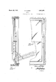
` 4"" Figurel,illiistratesa'sectional elevation o fthe invention wherein the sashes ,arev also in`` -dicated in their substantially horizontal 'positions, and v 'i v' f f' 'F'gure 2 shows 'a partial front elevationrof Figure 1T` f i onto the upper extremity fof one side of,y the 6 6: of 'Figure 3.
' VFigure 3 isa side' elevation'jo-f a guide fand Sash plate employed. for
holding onefside of. theupper sash.- m 'f i" Figurek 4 is anenla'rged plan view looking,
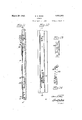
upper :sash and its slide when the formerv `is vertically positionedrf l l Figure 5 isan enlarged detail showing latchk by which i the f Figurer? Sash plate employed `for holding one sideof the vlower sash, and the latter in `Ventilating position. 'f
the upper sashv isfretained in A `vert1calpos1t1on4 I f f f Figure 6 1s an enlarged Section on'the-line Y is aside elevation of a guide and e' Figure 8L is Section `onthe line 18-.8 of. f
'Figure 7. I
vFigure 9 is an Venlargedfplan viewshowingV y `the upperextremity' of one side of the lower sash when the latter is verticallyV positioned, Y f
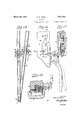
in alignment with one of its'slide's, and Y Figure 10 is an enlarged Vdetail showi'ng'the -Y' samefformof locking arrangement.' 7 Y Figures 11 and 12 show Sections on the lines 11-11vfand12-112 of Figures 12 andll respective'ly, andr depict the slide holding Tarrangement `for the lower sash whenthe latter and its arms yare moved outwardlyfromy the Y n Figures 13 and 14 are enlarged detailskFigure-15 is an elevation of -theoutlersideV ,'ofaslideand a sashplate-and sash in ven-V I ytilati-ug position, with another form of sash Y' locking device thereon.
Figure 16 is an .enlarged detail ofthe sash p loclring-devicreshown in Figure 15.
Figures 17,and*18aresectionsonthelines i e Y i V90 Y.
' slidable inthe grooves 2 and f3 arefupperi and lower slides 4f and 5 respectively-*both of?` WhichVare 4substantiallyjofchannelYSBCtionY n, and havetheirop'en Sides outwardly "disc posed." f" On the inner sides oliV the vslide's 41 and 5 are Sash plates f6 and 7 respectively which are pivotally and removably mounted posed, and in thevfront faces of the slide's .4
and 5 adjacent their inner margins grooves 10 and 41 are formed throughout'their length f to receive outwardly and rearwardly extendn ing projections 11 and 42 on the plates 6 and 7 respectively, so that the cooperating portions 10 and 11, and 41 and 42, function as weather- Y stripng when the sashes are vertically disf pose f Intermediately of their length and width the sash plates 6 and 7 each have, on their inner sides, a pair of parallel and longitudinal ribs 12 and 13, and 43 and 44, respectively. Y The front ribs 12 and 43 extend inwardly further than the rear ribs 13 and 44. Longitudinally of these sash plates adjacent their inner sides stepped projections 14 and 45 are also formed to receive the front vertical corners of the sashes 8 and 9, the sides of which also rest against the front ribs 12 and 43. Between each pair of ribs 12 and 13, or 43 and 44m a. longitudinal slot 15, or 46, is formed in which an outwardly projecting tongue 16, or 47, integral with a sliding member 17, or 48, is arranged.v
V`The members 17 and 48 lie substantially parallel with the sides of the sashes 8 and 9 respectively, and are of such thickness that they may move freely between the latter and theinner ribs 13 and 44. 18 and 49 indicate vscrews extending through the sashplates 6 `I will now describe in detail the mounting of the lower sash plates 7 on their slides 5, reference being had to Figures 7 and 11 of the drawings.
Extending outwardly from the sash plates 7 adjacent their lower extremities are hinge pins 19 having annular flanges 20 around them a short distance from their outer ends;
n these flanges are also spaced from their sash ner side of eachk flange 20 bears against the Vsash cords-not shown.
outer side of the central portion of one of the slides 5 kand the outer ends of the hinge pins-19` extend into the apertures 23 in the flexible members 22. In order to remove the sash 9 all that need be done is to press the flexible'member 22 outwardly so that the pins 19 become disengaged from the apertures 23 the sash may then be moved downwardly 'relative to the slide 5 and the pins 19 then move out of engagement from the slots 20.
Within the channel-shaped portion of the slides hooks 24-as shown in Figure ll-are provided to receive one end of conventional Through the slides 4 and 5 intermediately of their length slots 26 and 57 are formed through which locking pins 27 and 58 project. The method of supporting these pins is identical in both sashes and is clearly shown in Figures 11, 12 and 13. It consists in the provision of resilient menibers 28 and 59 secured within the slides, and the said members at their free ends encircle the said locking pins. In the rear margins of the sash plates 6 and 7 recesses 29 and 60 are formed which are so positioned that when the sash plates are vertically disposed their bases force the pins 27 and 58 rearwardlyagainst the tension of the resilient members 28 and 59, but when the sash plates 6 and 7 are moved forwardly at an angle to their slides 4 and 5 the pins are also moved forwardly by the resilient members 28 and 59 which` support them. On the opposed faces of the stile grooves 2 and 3 opposed catches 32 and 61 are secured which have slots 31 and 62 respectively therein. These slots are adapted to receive the `pins 27 and 58 and hold the slides 4 and 5 against vertical movement; that is, of course, provided the sashes and sash plates are moved pivotally when the slides are at such heights that the pins will engage their respective slots.
Extending inwardly from the opposed faces of the stile grooves 2 are stops 30 with which the lower extremities of the slides 4 come into contact when in their bottoni position. kThe catches 32 are usually so positioned that the pins 27 will engage the slots 31 when the slides 4 rest against the stops 30.
Pivotally mounted on the inner sides of the slides 4 intermediately of their length are arms 33 having the sliding members 17 pivotally attached to'their opposite extremities. These arms are so placed that when the sash plates 6 are in their normal vertical positions the said arms lie in the cut away intermediate portions 106 of the sash plates 6. As the sash 8 and sash plates 6 swing inwardly the tongues 16 of the members 17 travel downwardly in the sash plate slots 15 until the arms 33y strike the rearwardly projecting shoulders 106a formed at the lower ends of the cut away portions 106. thereby preventing further pivotal movement of the sash plates 6.
susL
j YPivotallymountedon:thelllersides of the slides 5 intermediately oftheirj length are n arms 70, whichl extend yupwardly from their s pivotal ends and, have '.pivoted f extensions 7l u connected to them .by 4pins 71a Yin alignment with the. axes of the arms.. 7 0. vThe latter and their extensions are so :placedthat when the fr sashplates 7 arein their normal positionsthe said arms lie in the cut away portions 107 of op Tthefslides 7. The sliding members 48 arer pivotal: on the'outer extremitiesof the eXten- Y sions 71 so. thattheir tonguestravel longitui VVdinally of the, slots 46 as thesash 9 and sash plates 7 are movedy pivotally.
Secured within the channel shapedrslides 5 are resilient members 72 each of which-hasV two` inwardly extending projections 73 and i the sash 74thereon. 1 The projections are located adjacent rthe Vfree ertremities'of theirmem-VA throug'hcopenings 76'for1fned through the inner sides vofgthe slides 5; The projections F4 301normallylie'adjacent the front ofthe arms 70y "and prevent VthemV from moving fpivotally; In the ,opposed faces of the stile grooves 3 holes 77 are formed so-that when the slides 5 haveV been moved to. a predeterminedvertical position the projections @73, may 4bejpre'ssed Aoutwardly so thattheir outer V:extremities Y enter the holes 77;*when. thisoccurs'lth'e p ro-y jections 76 alsoV move outwardly sufficiently" to permit the arms 0 to passthjein Thenyof {eib.,Y n ,t The ylatches shown -in` detail Figures 9 c and 310, ,which are sometimes employed *for Lholding Vthe lowersash plates in alignment course, the sash plates 7 and sash 91arc. free to move pivotally downwards about their :pins Ql9j into their substantially horizontalfposif tions@Y Y, The latches 80 for the uppersash consist ofj catches V81V,y pivoted withiny the channelY` 'shaped slides 4whichfare'normally held in the position shown in Figure -5- by springs'82;
When the fingerholds; 81a integral fwiththe said 'catches are moved upwardly'Y the engag' e ing portions 81?),v also integral with vthe said catches; become disengaged'from recesses 83 formed 1in the upper extremities (of theV sash 'plates 6L; 8f4 denotes a Ascrew vwhich maybe Varranged to project from the Window-frame 1 sozthat when the-sash 8 has been lowereda "givenV distance thesash plates 6 are automatlcally released by thecatchengaging pn'vtioitsv with the'lowerzslides consist ofV catches-*386 V-r pivoted` on -,the said-sashjplat'es.Y Integral'.
with the catches 86 "are ingerholds 86a and engaging' portions 86?) V; Amoreover the latter normally lie in recesses 87 ormedjtransverse lyof the Yupper margins the said slides,
and Vare vheld therein bysprings88 -Whichy form portions of thesaidvlatches. 'i v From the `foregoing it will-be clearly seeny y' thatlthe, upper slides e, sash .plates 6 and sashk 8 may be moved vertically in the stile grooves y2 inthe normal mannersthat the catches'8l maygloer released at any vertical position of the slides Lisovthat thesashS may swing in,- wardlylfon theslides; and that the slides 4 remain vertically'movable whether the sash 1 8is in alignment with them'or not until the pins27 engage the slots 3liins-the catches32.k s
Moreover the tapered margins 32afof'the lat, yter are so shaped that thejpins 27 automaticallyengage the slots 31 as soon as the pins and slots comeopposite one another provided j position. A
The lowerrrsash 9;and sash plates?? may be moved Vinto the Ventilating position shown thestilegrooves, but` untilthejpins 73 are in alignment with the stilegroove'holes 77 the projectionsV 7 4 cannot'bejr'noved inwardly tov l8`has been "moved intoianinclined release thearms 7()y andfpermitjtheir pivotal Y movementl y Y In :both the upper and lower sash mounting 'arrangements longitudinal slots 155 ori 46,
arm formediin the inner rsides" of'lthe sash or 71- and 70 move pivotallyz Y L Referring now to the sash locking y yment shownin Figures 15 to 18y inclusive, I n
as i i [plates/6,l or-7,ain which :the tongues;`16,^or` i 4:7, areadapted to slide aslthe arms 33,"01271,Y
theouterfsides ofthe sash 9 and covered bv l its sash plates 7 are apertures 100, ,inl which a blockxlOl is arranged. Eachof the latter is lheld in vposition against its isash plate 7 fas byscrewsl02; Longitudinally onthe inl ner sideof the block 101,th`at yis on the side yofthelatter remote Afrom itssash plate, a ilat lspring A103 is'arranged which has one extrem# ityy secured to the said block. Movable" throughV an opening i104 @throughv the block is r'as-locking'member V105 which vprojects be-y yond the latter and has ai recess 196 formed transversely across it adj acentits outerex'- f tremity` {Theinnerend of the locking mem ber l05is secured tothefree end of the spring v103.4 f
Transversely of the underside of the block inner end so that that .extremity of the slot is deeperthankits outer portion. The freeler-A ftremity of lthe spring-103 extends across `the of s v open side ofxthe slot 97.v Y
lN/Iountedy on the front ofthe sash 9V and on each sidelthereofgare bearings; 108 in -which handles 109` are pivotally mounted. :.Extendf, ing upwardly fromfeachf'handleis a1 cylindrii" i lcal elementV fllOf:Y which projects radially f `10]. aslot 97 is formed which Ais tapered at' its *n n xao `through a pin 1171` Aon which Aan arm 112 `is ros tatablymountedQ .A portion of the undersidey ;A oifthe ylatter is cutawayto clear theelement away from the block 101. This movement ob,`
viously draws the locking member 105 inwardly relative to the block 101'andsash plate 7 .v
The locking member 105 normally extends across the path of travel of the sliding member 48 and projects through an aperture 118 in the slide 5 thus holding the latter and the sash plate 7 against independent movement. When the handle 109 is raised and thevarm 112 moved rearwardly the locking member is moved inwardly suliiciently for the slider 5 to be released and also 'for the recess 100 in the said locking member to come into alignment with the sliding member 48 so that a portion of the latter may pass therethrough. The upper and lower margins 48a and'48b of the member 48 rest adj aceiit the lower and upper sides respectively ot the locking member 105 when the sasli is in Ventilating and closed positions respectively. n Therefore when the sash is in ventilating position the locking member prevents the sash from moving towards its closed position and the projection 7 4 which limits themovenient of the extension 71 in a downward direction `prevents the sash from swinging further downwardly, thus the sash is held substantially immovable in Ventilating position in part by the locking device now described. Accidental releasing of the sliding members 48 can only occur when the handle 109 is accidentally raised, since the spring 103 always returns the locking member 105 into such position` that its recess 96 is out of alignment with the sliding memberl 48 and into engagement witl the slide aperture 118. While in the :foregoing the preferred embodiments of the invention have been de`` scribed and shown, it is understood that the construction is subject to such further alterations and modifications as fall within the scope of the appended claims.
What I claimas my invention and desire Y j tures therethrough'adapted to encircle the to secure by Letters Patent is: n
1. In a. window, the combination of a frame having stile grooves therein, slides vertically movable in saidr grooves, the latter having holes formedy in their bases, asasli pivotedbetween said slides, arms pivoted on said slides, extensions on said arms, said extensions being slidable on said sashsides and adapted to move pivotally on said arms at yany vertical position of said slides,kmeans `adapted to hold said arms kagainst pivotal tions are in alignment with the holes formed i in the stile groove bases which may then receive them.
2. In a window, the combination of a frame having stile groovesy therein, slides vertically movable in said grooves, a sash pivotally mounted between said slides, arms pivoted on said slides, extensions pivoted on said arms having their opposite extremities slidable on said sash, said extensions being adapted to move pivotally on said arms at any vertical position of said slides so that limited pivotal sash movement may be obtained, liexible members mounted on said slides having projections thereon, said slides having apertures therethrough, one projection on each member being adapted to extend through one aperture in its slide and prevent pivotal movement of the arm Vmounted thereon, and the other projection on each membery being opposite another slide aperture and also extending outwardly, and said sash grooves having opposed holes formed therein so that when the sash is at a predetermined height said other projections mayv be moved outwardly by pressure exerted on them through the slide apertures in registry with them thereby causing the said other projections to enter the stile groove holes, and this movement causing the armrengaging projections to release said arms. Y
3. In a window, the combination of a frame having stile grooves therein, slides vertically movable in said grooves, a sash, sash plates secured to the vertical margins of said sash, hinge pins extending outwardly from the lower margins of said sash plates, said slides having longitudinal slots formed therein which extend upwardly from their lower extremities, flanges on said pins intermediatelyof theirlength adapted to rest against the outer sides of said slides, and resilient members on the outer slide sides having aperouter extremities of said hinge pins so that when said resilient members are flexed outwardly they become disengaged from the yhinge pins and the sashmay be moved downwardlv so that the n pins are moved out of the slide slots.l f
Y having openings therethrough, resilient m'embers on theouter sides kof'said slides, :pins
mounted onthe free extremities ofsaid resilient members and extending through said slide openings,`c`atc hes secured to saidv stile grooves` having slots therein, sash 4plates pivoted on said slides having recesses formed in theirr outer margins adapted/to hold said pins against the tension of the `Vresilient members when thes'ash plates are in alignment with 'the slides, and said pins being adapted'to be moved inwardlyr Yby saidf resilient members relative .to their slides when the sash platesv are inclined so that thejpins engage the catch`v slots when the pins and lslots are in horizony tal alignment,said sash plate secured to the slide, hinge pins extending outwardly from the lower margin of the sash plate, said slides having longitudinal rslots formed ltherein which extend upwardly from their` lower extremity, aresilient member encircling theend of the hinge pin so 'that when said resilient members are flexed outwardly theybecome Y disengagedtrom the `hinge pinsand the sash maybemoved downwardly so that the pins are moved out from the slide slot.
j a recess'formedtherein to receive said catchv Y vertical position.
p6. Ina window, the combination of slides "i adapted to be moved vertically in stile grooves,l sash plates pivoted on said slides, hinge pins, having `flangeV portions thereon', extending outwardly from,y the lower mar-` gin of the sash plate said slides having longitudinal slots formed therein which extendupj wardlyfrom theirV lower extremities, a resil' ient member encircling theen'd of the hinge fpins, a sash held betweenthe sashy plates and-y havingan aperture formed therein'under one sash plate, a sliding member slidable longi-r` tudinallyfbetween the sash and the last named a predetermined sash plate, alocking member movableat right anglesfto the direction of, movement of the'r sliding :member inl the sash aperture and Vthrough-'the adjacent y'.sasjli'prlate, saidA lool;-
ing member.KIA having-a` transverse: groove yformed therethroughwhich may be broughtr into alignment `with, theA sliding `[mennber and thereby' permitting passage `of the latter past theloclring member, means' for moving `the f. latter,"andanarm-pivoted onA one slide which is connected to said slidingsmember. n f
l. r7. In a window, thev combination as Idescribed in claim 6, whereinthe slideadj acent,V the locking member hasan aperture therein into which Vthe said looking member normally4 extendswhen the sash andv slides are in align-y g ment with rone another. 1 r
jacent sash plate, a locking member slidable plate, a spring secured to the side of the block through said block and the adjacent said" remote from tliesashplate to which it is seslidev 'having an a1 erture therethrou hl, into Awhichsaid lookin g member projects when the sashis in alignment with the slides,"a slidadapted lto be moved vertically in slide "5' cured, one extremity ot said locking member 1 beingqsecured to said spring, thefadjacent ing member slidablelongitudinallybetween l the sash and tlie'sash plate through which the 1go' Y ,in j
locking member projects, saidlockingmember having a transverse recess formed there through, the `passage of the slidingmember o.
past said locking member being normally ob-k structed by ythe latter, a handle pivoted on 'said sash, means connected to said handle for moving the locking member against the tension of the spring when the handle is moved in one direction so that .the locking member recess comes into alignment with the'sliding.V
member so that the latter may pass there-- through and the locking member .movement also causing said member to disengage the slide aperture, and arm pivoted on one slide,
and means connecting said arm. withsaid Y sliding member.
, 9. In a window, the combination of a frame having stile grooves therein, slides vertically movable yin said grooves, a sash secured to the slides, hinge' pins, having flange portions i thereon, extending outwardly from the lower margins of the saslnfsaidslides having longitudinal slots rformed therein which extend upwardly from their lower :A extremities, a resilient memberA encircling lthe end` oi' the hinge lpin, arms pivoted on said slide, extensions pivoted on said arms, having theirl opposite extremities slidable on said sash,
said extensions being adapted to move pivotf ally onxsaid arms'at yany vertical position of said slides so that limited pivotal sashmovelos,A f
ment may be obtained, exible members mounted on said slides having projections thereon, said slide having apertures therethrou h, one projection on each member being a apted to extend through one of the apf ertures in its slide and prevent pivotal move- 1 ment of the arm thereon, and the other proi jection on each member being opposite another slide aperture and also extending outl wardly, said sash grooves having opposed holes formed therein so that when the sash is at a predetermined height said other projections may be moved outwardly by pressure exerted on them through the slide apertures in registry with them, thereby causing said other projections to enter the stile groove holes, and this movement causing the arm engagement projection to release said arms.
EDWIN D. ROSS.
Priority Applications (1)
| Application Number | Priority Date | Filing Date | Title |
|---|---|---|---|
| US445020A US1851293A (en) | 1930-04-17 | 1930-04-17 | Window |
Applications Claiming Priority (1)
| Application Number | Priority Date | Filing Date | Title |
|---|---|---|---|
| US445020A US1851293A (en) | 1930-04-17 | 1930-04-17 | Window |
Publications (1)
| Publication Number | Publication Date |
|---|---|
| US1851293A true US1851293A (en) | 1932-03-29 |
Family
ID=23767317
Family Applications (1)
| Application Number | Title | Priority Date | Filing Date |
|---|---|---|---|
| US445020A Expired - Lifetime US1851293A (en) | 1930-04-17 | 1930-04-17 | Window |
Country Status (1)
| Country | Link |
|---|---|
| US (1) | US1851293A (en) |
Cited By (2)
| Publication number | Priority date | Publication date | Assignee | Title |
|---|---|---|---|---|
| US2784460A (en) * | 1955-05-12 | 1957-03-12 | Isaac R Rinkewich | Slidable and hinged window sashes |
| WO2018013980A1 (en) * | 2016-07-14 | 2018-01-18 | Amesbury Group, Inc. | Upper tilt-in double hung window |
-
1930
- 1930-04-17 US US445020A patent/US1851293A/en not_active Expired - Lifetime
Cited By (2)
| Publication number | Priority date | Publication date | Assignee | Title |
|---|---|---|---|---|
| US2784460A (en) * | 1955-05-12 | 1957-03-12 | Isaac R Rinkewich | Slidable and hinged window sashes |
| WO2018013980A1 (en) * | 2016-07-14 | 2018-01-18 | Amesbury Group, Inc. | Upper tilt-in double hung window |
Similar Documents
| Publication | Publication Date | Title |
|---|---|---|
| US1851293A (en) | Window | |
| US1387302A (en) | Safety-lock for windows and the like | |
| US853507A (en) | Hinge. | |
| US2723412A (en) | Cleaning device | |
| US2804922A (en) | Venetian blind slat attachment | |
| US664993A (en) | Window. | |
| US1802904A (en) | Latch for tool handles | |
| US1948596A (en) | Window construction | |
| US1940099A (en) | Safety self-closing vehicle door hinge | |
| US1965250A (en) | Reversible window sash | |
| US837595A (en) | Door and window securer. | |
| US3473262A (en) | Window | |
| US1097524A (en) | Sash-window. | |
| US2707992A (en) | Storm screen window | |
| US1587831A (en) | Window | |
| US1999025A (en) | Window construction | |
| US362714A (en) | Silas s | |
| GB190701830A (en) | Improvements in Sliding Windows. | |
| US585510A (en) | Window | |
| US1568874A (en) | Window construction | |
| US1344532A (en) | Window-frame with sash-cord holder | |
| US1987565A (en) | Storm sash fastener | |
| US1636762A (en) | Window | |
| US1117954A (en) | Window. | |
| US1780274A (en) | Ventilating window lock |