US1851290A - Liquid dispenser - Google Patents
Liquid dispenser Download PDFInfo
- Publication number
- US1851290A US1851290A US433941A US43394130A US1851290A US 1851290 A US1851290 A US 1851290A US 433941 A US433941 A US 433941A US 43394130 A US43394130 A US 43394130A US 1851290 A US1851290 A US 1851290A
- Authority
- US
- United States
- Prior art keywords
- valve
- rotor
- opening
- lever
- cover
- Prior art date
- Legal status (The legal status is an assumption and is not a legal conclusion. Google has not performed a legal analysis and makes no representation as to the accuracy of the status listed.)
- Expired - Lifetime
Links
- 239000007788 liquid Substances 0.000 title description 16
- 230000000994 depressogenic effect Effects 0.000 description 3
- 230000006835 compression Effects 0.000 description 2
- 238000007906 compression Methods 0.000 description 2
- 241000792859 Enema Species 0.000 description 1
- 241000036848 Porzana carolina Species 0.000 description 1
- CDBYLPFSWZWCQE-UHFFFAOYSA-L Sodium Carbonate Chemical compound [Na+].[Na+].[O-]C([O-])=O CDBYLPFSWZWCQE-UHFFFAOYSA-L 0.000 description 1
- 229940000425 combination drug Drugs 0.000 description 1
- 238000010276 construction Methods 0.000 description 1
- 230000000881 depressing effect Effects 0.000 description 1
- 239000007920 enema Substances 0.000 description 1
- 229940095399 enema Drugs 0.000 description 1
- 239000012530 fluid Substances 0.000 description 1
- 230000006870 function Effects 0.000 description 1
- 210000004907 gland Anatomy 0.000 description 1
- 238000005086 pumping Methods 0.000 description 1
- XLYOFNOQVPJJNP-UHFFFAOYSA-N water Substances O XLYOFNOQVPJJNP-UHFFFAOYSA-N 0.000 description 1
Images

Classifications
-
- B—PERFORMING OPERATIONS; TRANSPORTING
- B67—OPENING, CLOSING OR CLEANING BOTTLES, JARS OR SIMILAR CONTAINERS; LIQUID HANDLING
- B67D—DISPENSING, DELIVERING OR TRANSFERRING LIQUIDS, NOT OTHERWISE PROVIDED FOR
- B67D1/00—Apparatus or devices for dispensing beverages on draught
- B67D1/08—Details
- B67D1/12—Flow or pressure control devices or systems, e.g. valves, gas pressure control, level control in storage containers
-
- B—PERFORMING OPERATIONS; TRANSPORTING
- B67—OPENING, CLOSING OR CLEANING BOTTLES, JARS OR SIMILAR CONTAINERS; LIQUID HANDLING
- B67D—DISPENSING, DELIVERING OR TRANSFERRING LIQUIDS, NOT OTHERWISE PROVIDED FOR
- B67D1/00—Apparatus or devices for dispensing beverages on draught
- B67D1/04—Apparatus utilising compressed air or other gas acting directly or indirectly on beverages in storage containers
-
- Y—GENERAL TAGGING OF NEW TECHNOLOGICAL DEVELOPMENTS; GENERAL TAGGING OF CROSS-SECTIONAL TECHNOLOGIES SPANNING OVER SEVERAL SECTIONS OF THE IPC; TECHNICAL SUBJECTS COVERED BY FORMER USPC CROSS-REFERENCE ART COLLECTIONS [XRACs] AND DIGESTS
- Y10—TECHNICAL SUBJECTS COVERED BY FORMER USPC
- Y10T—TECHNICAL SUBJECTS COVERED BY FORMER US CLASSIFICATION
- Y10T137/00—Fluid handling
- Y10T137/8158—With indicator, register, recorder, alarm or inspection means
- Y10T137/8225—Position or extent of motion indicator
- Y10T137/8259—Selection from plural branches
-
- Y—GENERAL TAGGING OF NEW TECHNOLOGICAL DEVELOPMENTS; GENERAL TAGGING OF CROSS-SECTIONAL TECHNOLOGIES SPANNING OVER SEVERAL SECTIONS OF THE IPC; TECHNICAL SUBJECTS COVERED BY FORMER USPC CROSS-REFERENCE ART COLLECTIONS [XRACs] AND DIGESTS
- Y10—TECHNICAL SUBJECTS COVERED BY FORMER USPC
- Y10T—TECHNICAL SUBJECTS COVERED BY FORMER US CLASSIFICATION
- Y10T137/00—Fluid handling
- Y10T137/8593—Systems
- Y10T137/87056—With selective motion for plural valve actuator
Definitions
- the object I havev aecon plished is the construction of a device here an operator can selectively dispense] one of .afplurality oi liquids through a'single discharge pipe, It has primarily been desi-gnedtodispense oiltwhere a merchant keeps a: plurality of 'gradesand brands in separate containers but it can be used for dispensing soda Water 0t varionsflavors or other liquids. Anotherobject iscompactness and easeof operation. s
- Figure lot the drawings is a fractional, vertical, sectional View of the device with parts-cut away- FigureQis a top .vieW of the device.
- Figurefi is a cross sectional View along (the section line 3-3 in Figurel. ure tisa crosssectionalview o t the-device along the sectionjli ne 44 in Figure '1.
- Fig a head or block 50., having thetop re Obsabled to form ajdepression or cup 61.
- Arotor 26 1s constructed .to' ro tatingly fit Withinthe cylinderba. To-inalre said lit-oil tight rings can he used grooves lathe rotor adapted for the lnsertron of. sa d rings.
- Fig, 2 which shows a 'pluralityoi oblong lettered designs 38 each of which letters in 1930.
- each valve cage opening an auxiliary chamber 40 ofless' diameter than the valve cage chamber A lead 37 -connectschamber 4O with a pipe 62, 60 which pipe leads to the source of supply of the oil or fiuidto'be dispensed,
- Figv II have shown pipe 62 entering a tank partly" filled with liquid 6-3,,a compressed air re'ser- I voir 32, and aiconnection between, the top" of the tanlr andthe compressed air reservoir, sora constant pressure of air can be had on thetop of the liquid in tank 33.
- I ,A galve cage 22 is formed to fit. Withinthfe valve cage chamber, said valve cage having ing a valveseat fie formed at thebet'tom.
- a valve-2O is adapted tocooperate with the valve seat 65.
- a The top ofthe'valve cage 19 is, adapted as a closure for thev'alve cage chainhe'r and also as -a guide for the SiZEIIL'Of valve 2O. It is noted that the relation ofthe' valve seat and the-valveis that the pressure a of the oil or, liquid through lead 37 Will tend to keep the valve closed, and on opening the valve, chamber 'iseadapted to receive the I head of the valve so the fluid can flow through opening37,?anound the valve and into the valve cage.
- f p r i From each valve cage and valve cage chan1- her is a lead 28 to cylinder 54, all ofwhich openings should be.
- the rotor has a conduit 6textending'froin' the bottom of the rotor" to a fixed locationon its periphery, positioned so that one endof the leadfis constantlyopen into 'well36' regardless'ofthe position of the rotorwithin thecylind gland theotherend of the conduit aligned to with each of the leads 8 as the rotor i s turned onits axis. It will e seen that by rotating the rotor the operwe can selectively register [a complete open net frorn the discharge pipe 29' to either, of
- the to of the valve stem terminates with a base 1 and by inserting a compression spring 18 between base 17 and closure 19, the valve will normally be kept closed.
- To open the valve I have pivoted one end of lever 16 to a depending lug on the under side of top or cover 13, a spaced distance from the center of said top and have positioned the lever parallel to a radius of the cover so that the free end thereof is adj acent to the center line of the cover.
- the lever will rotate with the cover, and a portion of the lever between the pivoted and free ends will pass over the tops of the valves in such rotation.
- a plunger 11 is adapted to cooperate with the free end of lever 16.
- lever 16 and lead 64 are such that when lead 64 registers with the opening 28 of any valve cage chamber the lever will be positioned over the valve stem cooperating with that one valve cage chamber.
- said selected valve will be opened and the other valves will be normally closed by means of spring 18.
- the plunger stem is easily depressed by pressing on the top of plunger headlO.
- auxiliary compression spring 23 which is depressed when the plunger is depressed and holding the valve open.
- lever 16 and plunger 11 On the release of pressure from the plunger, lever 16 and plunger 11 is raised.
- a cap 24 covers the top of spring 23, forming a head for spring 23.
- Spring 23 and cap 24 are contained in the hollow portion of stem 60.
- a hole 67 through knob 12 serves as a guide for the plunger.
- a slot 25 in stem serves as a guide for the free end of lever 16, and
- ' also acts as a stop to limit the up and down movement of lever 16 and thereby limit the opening of the valve.
- An indicator 9 is attached to a fixed point on block 50.
- the cover is rotated so that the A design is adjacent to. the indicator.
- the opening 28 in the chamber having direct communication to the tank of oil also designated A will then register with conduit 64, and
- lever 16 will be in operative relation with valve 20 of the same chamber, and that valve only can be opened to function to discharge the oil.
- the oil can be discharged from the tank by air pressure as shown, but pumping or other well known means can be used to discharge the oil or li%id.
- Block 50 has a circular recess 51 formed on the periphery adjacent to the bottom end to receive housing 31 which is intended to cover the pipes 62 and any reservoir or other accessories desired to be placed therein.
- bracket 34 for convenience in supporting the measure or container into which the liquid is drawn.
- a liquid dispensing device the combi nation of a block having a cylindrical opening therein, a rotor adapted to fit and turn freely within the cylindrical opening, a plurality of valve chambers in said block,'each of said chambers having one lead to a source of liquid supply and a second lead to the cylindrical opening, a well in said block having a discharge opening therefrom, a conduit through the rotor positioned within the rotor so one end of said conduit opens into said well and the other end is adapted to selectively register with the lead to either one of said plurality of chambers, separate valve means for normally closing the flow of liquid to each of the valve chambers, means for i I normally keeping all of said valves in a closed relation and means for opening the valve within either of said valve chambers,
- a liquid dispensing device thecombination of a block having a cylindrical opening therein, a plurality of valve chambers positioned within said block equi-distant from the wall of the cylindrical opening, each valve chamber having a lead to a source of liquid supply and a separate lead to the cylindrical opening, the leads to the cylindrical opening being all aligned on the wall of a common cross section of the cylindrical opening, a rotor adapted to fit and to rotate within the cylindrical opening, a well formed within the block adjacent to the bottom of cylindrical opening, a discharge opening connected with said well, a conduit through the rotor one end of which communicates constantly with said well in the rotation of the rotor, the other end of said conduit being adapted to register with each of the leads into the cylindrical opening during the rotation of said rotor, and to register with one only at a time, a dial attached to the rotor having designations thereon for each of the plurality of valve chambers, a valve in each valve chamber adapted to cut off the flow of liquid into the valve chamber
Landscapes
- Devices For Dispensing Beverages (AREA)
Description
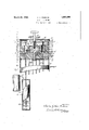
'LIQUID DISPENSER Filed March 7 1950 2 Sheets-Sheet 1 ATTORNEY I. INVENTOR. v
a UNI ED-TSTAFS e Patented Main 29, 1932' rise as dens ties A THUR PERKINS, or: r'nnsivo, oemronma j Lmuxnmsrnnsnn' Application filed March 7,
- My invention relates: to a device for dispensing liquids; The object I havev aecon plished is the construction of a device here an operator can selectively dispense] one of .afplurality oi liquids through a'single discharge pipe, It has primarily been desi-gnedtodispense oiltwhere a merchant keeps a: plurality of 'gradesand brands in separate containers but it can be used for dispensing soda Water 0t varionsflavors or other liquids. Anotherobject iscompactness and easeof operation. s
Figure lot the drawings is a fractional, vertical, sectional View of the device with parts-cut away- FigureQis a top .vieW of the device. Figurefi is a cross sectional View along (the section line 3-3 in Figurel. ure tisa crosssectionalview o t the-device along the sectionjli ne 44 in Figure '1.
Referring to the --drawings, in Fig: is shown a head or block 50., having thetop re cessed to form ajdepression or cup 61. Inthe bottom of the cup alcylinder 54: is formed,
; I thecylinder. being of less diameter than the diameter of-thei cupz, in the bottom ofthe cylinder a 181136 is horedxvhich shonld be of. less diameter thanjthepdianieter of the cylinder. Tell 36 has outlet 29 to the outside of. block 50. At the botton of Well36 a 30 hearing hole '58 ismade. The cylinder and hearing hole should have a common axial line, and the ivell, 36 should surround the hearing hole. Arotor 26 1s constructed .to' ro tatingly fit Withinthe cylinderba. To-inalre said lit-oil tight rings can he used grooves lathe rotor adapted for the lnsertron of. sa d rings. T 0 the rotor isattached, afflshait 55 which inlthe bearing hole, 58. The rotor and shaft-are held in thefhl ock by means of ainnt 30. flaw ash ar 59 is inserted "between nut. 30and the block for the purpose of holding'inpositiori. packingfifi to-malre the hearing lealrpr'ootn. Rotor 26 has an upwardly extending. hollow fStQIll 60 to vhich is rigidly attached the cover :13, which cover, a is sure monntedhy a knob 12 by which knob enema bined rotor and cover canbe revolved."
separate View of the top or cover is shown in Fig, 2, whichshowgsf a 'pluralityoi oblong lettered designs 38 each of which letters in 1930. Serial No. 433,941.
oil or liquid, which can be drawn through the common discharge ,pipe,.the object for which will behereinafter described; WVithin the cup 7 and a nnlformly spaced distance from the 55 cylinder area plurality of valve cagechame bers 27. At the bottom oi each valve cage opening an auxiliary chamber 40 ofless' diameter than the valve cage chamber: A lead 37 -connectschamber 4O with a pipe 62, 60 which pipe leads to the source of supply of the oil or fiuidto'be dispensed, In Figv II have shown pipe 62 entering a tank partly" filled with liquid 6-3,,a compressed air re'ser- I voir 32, and aiconnection between, the top" of the tanlr andthe compressed air reservoir, sora constant pressure of air can be had on thetop of the liquid in tank 33. I ,A galve cage 22 is formed to fit. Withinthfe valve cage chamber, said valve cage having ing a valveseat fie formed at thebet'tom. A valve-2O is adapted tocooperate with the valve seat 65. a The top ofthe'valve cage 19 is, adapted as a closure for thev'alve cage chainhe'r and also as -a guide for the SiZEIIL'Of valve 2O. It is noted that the relation ofthe' valve seat and the-valveis that the pressure a of the oil or, liquid through lead 37 Will tend to keep the valve closed, and on opening the valve, chamber 'iseadapted to receive the I head of the valve so the fluid can flow through opening37,?anound the valve and into the valve cage. f p r i From each valve cage and valve cage chan1- her is a lead 28 to cylinder 54, all ofwhich openings should be. aligned on a common plane aspa'ced distance from the bottom; of the cylinden: 7' 5 I j The rotor has a conduit 6textending'froin' the bottom of the rotor" to a fixed locationon its periphery, positioned so that one endof the leadfis constantlyopen into 'well36' regardless'ofthe position of the rotorwithin thecylind gland theotherend of the conduit aligned to with each of the leads 8 as the rotor i s turned onits axis. It will e seen that by rotating the rotor the operwe can selectively register [a complete open net frorn the discharge pipe 29' to either, of
the plurality of tanks shown excepting for the restrictions of valves 20.
The to of the valve stem terminates with a base 1 and by inserting a compression spring 18 between base 17 and closure 19, the valve will normally be kept closed. To open the valve I have pivoted one end of lever 16 to a depending lug on the under side of top or cover 13, a spaced distance from the center of said top and have positioned the lever parallel to a radius of the cover so that the free end thereof is adj acent to the center line of the cover. The lever will rotate with the cover, and a portion of the lever between the pivoted and free ends will pass over the tops of the valves in such rotation. A plunger 11 is adapted to cooperate with the free end of lever 16. The position of lever 16 and lead 64 are such that when lead 64 registers with the opening 28 of any valve cage chamber the lever will be positioned over the valve stem cooperating with that one valve cage chamber. When the lever is positioned over a selected valve, by depressing plunger 11, said selected valve will be opened and the other valves will be normally closed by means of spring 18. The plunger stem is easily depressed by pressing on the top of plunger headlO.
For the purpose of returning the plunger and lever to an inoperative position, and for releasing the lever from the base of the valve stem so the cover and rotor can be freely rotated, I have provided'an auxiliary compression spring 23 which is depressed when the plunger is depressed and holding the valve open. On the release of pressure from the plunger, lever 16 and plunger 11 is raised. A cap 24 covers the top of spring 23, forming a head for spring 23. Spring 23 and cap 24 are contained in the hollow portion of stem 60. A hole 67 through knob 12 serves as a guide for the plunger. A slot 25 in stem serves as a guide for the free end of lever 16, and
' also acts as a stop to limit the up and down movement of lever 16 and thereby limit the opening of the valve.
An indicator 9 is attached to a fixed point on block 50. When it is desired to dispense a special brand of oil, as for instance the A brand, the cover is rotated so that the A design is adjacent to. the indicator. The opening 28 in the chamber having direct communication to the tank of oil also designated A will then register with conduit 64, and
lever 16 will be in operative relation with valve 20 of the same chamber, and that valve only can be opened to function to discharge the oil. I It is here noted that the oil can be discharged from the tank by air pressure as shown, but pumping or other well known means can be used to discharge the oil or li%id.
or the purpose ofholding the cover in positlon over the selected valve, I have attached a catch and spring assembly 8 to the under side of the cover, and have formed a notch 14 on the inside wall of cup 61. When the rotor and cover are turned to cooperate with any one selected valve, the catch will engage one of the notches 14. Block 50 has a circular recess 51 formed on the periphery adjacent to the bottom end to receive housing 31 which is intended to cover the pipes 62 and any reservoir or other accessories desired to be placed therein. To thishousing I have attached a bracket 34 for convenience in supporting the measure or container into which the liquid is drawn.
I claim as my invention:
1. In a liquid dispensing device the combi nation of a block having a cylindrical opening therein, a rotor adapted to fit and turn freely within the cylindrical opening, a plurality of valve chambers in said block,'each of said chambers having one lead to a source of liquid supply and a second lead to the cylindrical opening, a well in said block having a discharge opening therefrom, a conduit through the rotor positioned within the rotor so one end of said conduit opens into said well and the other end is adapted to selectively register with the lead to either one of said plurality of chambers, separate valve means for normally closing the flow of liquid to each of the valve chambers, means for i I normally keeping all of said valves in a closed relation and means for opening the valve within either of said valve chambers,
when the conduit and lead in said valve chamber registers.
2. In a liquid dispensing device thecombination of a block having a cylindrical opening therein, a plurality of valve chambers positioned within said block equi-distant from the wall of the cylindrical opening, each valve chamber having a lead to a source of liquid supply and a separate lead to the cylindrical opening, the leads to the cylindrical opening being all aligned on the wall of a common cross section of the cylindrical opening, a rotor adapted to fit and to rotate within the cylindrical opening, a well formed within the block adjacent to the bottom of cylindrical opening, a discharge opening connected with said well, a conduit through the rotor one end of which communicates constantly with said well in the rotation of the rotor, the other end of said conduit being adapted to register with each of the leads into the cylindrical opening during the rotation of said rotor, and to register with one only at a time, a dial attached to the rotor having designations thereon for each of the plurality of valve chambers, a valve in each valve chamber adapted to cut off the flow of liquid into the valve chamber, separate means for each valve adapted to close said valves, means attached to the dial and rotatable therewith adapted to open either of said valves, said opening means being positioned on the dial so the opening i meanswill be in operative relation only with the valve Within the valve chamber connected with the "well through said lead and conduit; hand means for opening said valve when the valve and opening m'eansare in operative relation.
CHARLES ARTHUR PERKINS.
Priority Applications (1)
| Application Number | Priority Date | Filing Date | Title |
|---|---|---|---|
| US433941A US1851290A (en) | 1930-03-07 | 1930-03-07 | Liquid dispenser |
Applications Claiming Priority (1)
| Application Number | Priority Date | Filing Date | Title |
|---|---|---|---|
| US433941A US1851290A (en) | 1930-03-07 | 1930-03-07 | Liquid dispenser |
Publications (1)
| Publication Number | Publication Date |
|---|---|
| US1851290A true US1851290A (en) | 1932-03-29 |
Family
ID=23722173
Family Applications (1)
| Application Number | Title | Priority Date | Filing Date |
|---|---|---|---|
| US433941A Expired - Lifetime US1851290A (en) | 1930-03-07 | 1930-03-07 | Liquid dispenser |
Country Status (1)
| Country | Link |
|---|---|
| US (1) | US1851290A (en) |
-
1930
- 1930-03-07 US US433941A patent/US1851290A/en not_active Expired - Lifetime
Similar Documents
| Publication | Publication Date | Title |
|---|---|---|
| US2248958A (en) | Dispensing device | |
| US2455962A (en) | Recording liquid dispenser | |
| US2445130A (en) | Liquid dispenser | |
| NO145598B (en) | DEVICE FOR APPARATUS FOR EXHAUSTING OF LIQUID OR CREAMMED PRODUCTS. | |
| US4274556A (en) | Dual dispensing container | |
| US2283529A (en) | Dispenser for liquid soap and the like | |
| US2532787A (en) | Bottle attachment for measuring doses by tipping | |
| US2639063A (en) | Sirup pump | |
| US795676A (en) | Dispensing apparatus. | |
| US2680455A (en) | Selector valve for dispensing liquid from a plurality of receptacles | |
| US1851290A (en) | Liquid dispenser | |
| US1886022A (en) | Liquid dispensing and measuring device | |
| US1753278A (en) | Liquid-dispensing apparatus | |
| US957669A (en) | Soap-dispenser. | |
| US1668897A (en) | Liquid vending machine | |
| US373537A (en) | smith | |
| US2588217A (en) | Liquid dispensing apparatus for dispensing measured amounts of beverages | |
| US1938892A (en) | Liquid dispenser | |
| US1204324A (en) | Liquid-measuring device. | |
| US228799A (en) | Aldrich | |
| US1401412A (en) | Faucet | |
| US1191484A (en) | Liquid measuring and dispensing device. | |
| US981296A (en) | Dispensing apparatus. | |
| US2084631A (en) | Beverage dispensing mechanism | |
| US2343024A (en) | Measuring and dispensing device |