US1851285A - Amusement device - Google Patents
Amusement device Download PDFInfo
- Publication number
- US1851285A US1851285A US414091A US41409129A US1851285A US 1851285 A US1851285 A US 1851285A US 414091 A US414091 A US 414091A US 41409129 A US41409129 A US 41409129A US 1851285 A US1851285 A US 1851285A
- Authority
- US
- United States
- Prior art keywords
- board
- cabinet
- guideway
- course
- balls
- Prior art date
- Legal status (The legal status is an assumption and is not a legal conclusion. Google has not performed a legal analysis and makes no representation as to the accuracy of the status listed.)
- Expired - Lifetime
Links
- 238000010276 construction Methods 0.000 description 2
- 230000000994 depressogenic effect Effects 0.000 description 2
- 238000007599 discharging Methods 0.000 description 2
- 241000048562 Anthopleura ballii Species 0.000 description 1
- 101150000595 CLMP gene Proteins 0.000 description 1
- 101100382322 Drosophila melanogaster Acam gene Proteins 0.000 description 1
- 101100001677 Emericella variicolor andL gene Proteins 0.000 description 1
- 241000135164 Timea Species 0.000 description 1
- 230000004888 barrier function Effects 0.000 description 1
- 230000015572 biosynthetic process Effects 0.000 description 1
- 239000011521 glass Substances 0.000 description 1
- 238000007689 inspection Methods 0.000 description 1
- 230000000284 resting effect Effects 0.000 description 1
- 238000005096 rolling process Methods 0.000 description 1
Images
Classifications
-
- A—HUMAN NECESSITIES
- A63—SPORTS; GAMES; AMUSEMENTS
- A63F—CARD, BOARD, OR ROULETTE GAMES; INDOOR GAMES USING SMALL MOVING PLAYING BODIES; VIDEO GAMES; GAMES NOT OTHERWISE PROVIDED FOR
- A63F7/00—Indoor games using small moving playing bodies, e.g. balls, discs or blocks
- A63F7/22—Accessories; Details
- A63F7/36—Constructional details not covered by groups A63F7/24 - A63F7/34, i.e. constructional details of rolling boards, rims or play tables, e.g. frame, game boards, guide tracks
- A63F7/38—Playing surfaces movable during play, i.e. games played on a non-stationary surface, e.g. the ball intended to be in permanent motion
- A63F7/386—Rolling boards adapted to be rocked during play
-
- Y—GENERAL TAGGING OF NEW TECHNOLOGICAL DEVELOPMENTS; GENERAL TAGGING OF CROSS-SECTIONAL TECHNOLOGIES SPANNING OVER SEVERAL SECTIONS OF THE IPC; TECHNICAL SUBJECTS COVERED BY FORMER USPC CROSS-REFERENCE ART COLLECTIONS [XRACs] AND DIGESTS
- Y10—TECHNICAL SUBJECTS COVERED BY FORMER USPC
- Y10S—TECHNICAL SUBJECTS COVERED BY FORMER USPC CROSS-REFERENCE ART COLLECTIONS [XRACs] AND DIGESTS
- Y10S206/00—Special receptacle or package
- Y10S206/80—Chewing gum
Definitions
- This invention relates to an amusement device and it is a general object of the invention toprovide a novel and attractive gaine 1 .or amusement device.
- the present invention is primarily concerned with an amusement device embodying means whereby a person employing skill is enabled to guide a ball or a like object over a track or course 'on'a tiltable board.
- the device is of a type that may be mounted in a case orcabinet so that it may beoperated by a personr at the exterior of the cabinet.
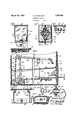
- Fig. 1 is a frontv elevation of the device provided by thisjinvention showing it enclosed or mounted in a'case or cabinet.
- Fig. 2 is a horizontal detailed sectional view taken as .e indicated in line 2 2 on Fig. 1, showing the board and other parts in elevation.
- Fig. ⁇ 3 is an enlarged vertical detailed sectional view being a view takenas indicated by line 3 3 y on Fig. 1.Y Fig.
- Fig. 4 is an enlarged vertical de- L -tailed sectional view of a portion of the devicebeing a view taken as indicated by line i-on Fig. 2.
- Fig. 5 is an enlarged ver- Vtical detailed sectional view taken as indicated on line 5-,5 on Fig. 2 showing the mounting ot the operating part of the de-r vice.
- Fig.v 6 is an enlarged horizontal detailed sectional view of the swivel mounting of the rear 'end of the board on the cabinet.
- Fig. 7 is a horizontal detailed sectional view taken as indicatedby line 7-7on Fig. 5.
- the amusement device includes generally a suitable lcaseV or cabinet l()7 a'tiltable board 1l mounted in the cabinet 10 and having a course 12 over which a ball, or like object, may be rolled, means 13 wherebya person at the exterior of thev cabinet 10 may operate or tilt the board 11, and means 14 y,for putting alball in play on the track 12.
- a suitable lcaseV or cabinet l()7 a'tiltable board 1l mounted in the cabinet 10 and having a course 12 over which a ball, or like object, may be rolled, means 13 wherebya person at the exterior of thev cabinet 10 may operate or tilt the board 11, and means 14 y,for putting alball in play on the track 12.
- the device provided by this invention y may be arrangedor mounted in any suitable form of case or cabinet or may be mounted on various types of supports.
- the device is designed to be arranged within a cabinet, or the like, and is constructed so thatit may be operated by a person aty the exterior of the cabinet.
- the device is also shown as including a coin actuated device that permits the operation of the amusement device only after'a coin has been dropped in the coin device.
- the device provided by this inventiony may be mounted iny manners differing somewhat from that illustrated in the drawings and may be constructedy so as to be operable at all times. Itisto be understood, therefore, that the invention is lar form of mounting or operating control ⁇ ,about to be described but is to be taken as including any features or modiiications that may fall within the scope of the claims.
- the particular form of cabinet 10 illustrated isl a box like structure mounted on a support 15.
- the cabinet l0 is rectangular and is provided with sides 16, a iront 17, a back 18, a bottom 19 and a top 20.
- the front 17 preferably consists of a base panel 2l and an upper transparent portion 22.
- the portion 22 may be formed of glass and is provided so that the board 11 and other parts i"
- the board 11 whiehisfarranged.; withinfv the cabinet 10 may be of any desired proper tioning, shape, or formation.
- Theboard; 1L is provided to supply a course over which an object, such as a ball,4 1nay ⁇ be-rolled3 andfis arranged in the cabinet so that it may. be,
- the board 1l is shown as being a substantially fiat quadrilateral member andisfarranged in the cabinet so as to be normallyl substantiallyhorizontal.
- the board 11' may be .disposedso that it is in a plane'somewhat. above the lower edge ⁇ of the transparent portion' ofsthef'ront.
- illu-stratedtlie board 11 is arrangedso thatone of'its corners is adjaeentthe back; 18of1'tlie cabinet. and' the opposite cornerof the board is at the in-. ner' sideV oft the front '17.A
- the other two .corners ofthe board are shown adjacent. the oppnsiteY sides ltfofithe' cabinet;
- the upperv side ofthe board is provided witheacourse 12 which maybe .in the nature of a groove.
- the course'12 mayextend from the ft'irwardl corner 23al ofl the board to the rear 23b of. theb'oardly
- the course 12' is preferablyi tortuoushaving'ar number of curves and contortions;
- Anopening 25' is providedv inthe course 12 ⁇ at' the rear cornerA 23b ofthe board'to allow a b'allfto fall outof' play after rolling overthe entire course.
- the coursel is shown as being a single Continuous course.
- a plurality ofopenings 26 is providedin the boardfl'l'adjacent'thecourse 12 to allow a ball todrop out ofiplay onto the tray 23 in the event that itleaves thecourse 1.2L
- a barrier or guard'27 is providediat the forward corner 23 of'the'board'to initially retain the balls in the course 12.
- the board is vswivelly ⁇ mountedin the cabinet by' means ofa stationary swivelconnection at one ofgits corners and is-supported at an opposite, corner by a. movable swivelv connection.
- illl'lstratedftheboardy 11 is supported at its'rear corner. 23b by a. stationary swivel connection and is supported ⁇ atV its. forward corner 23'@ by themeans 13..
- connection between the board and the back 18 of the cabinet includes two spaced brackets 27 fixed on the inner side of the back 18, a pin 28 extending between and rotatably carried by the brackets 27 and a horizontal stud 29 attached to the board 11 and extending through a transverse opening 30 in the pin 28. 'lhe'stud-29fis'rotatable inthe opening 30.
- the board 11 is adapted to be tilted vertically as well as to be turned or rotated on an axis extending between its corners 23@ and 23').
- the means 13 is provided to permit the boardl 11' tobetilted about the vertical and horizontalaxes ofthe connection at the rear.
- the rod 30 is preferably of round cross sectionalconfigura tion and ⁇ is rotatably carried in a transverse opening 31in a roller 32 rotatably carried by the panel -21.
- the roller 32 isarranged inan elongatedhorizontal opening33 in thepanel and isfprovidedfat its opposite ends with pins 34 rotatable in openings lin the panel 121;
- roller 32 and" is provided at its forwarder outer end with a handle 35. which is arranged at the exterior ofthe cabinet10. may be-in the nature ofa pistol. ⁇ grip handle.
- the rodf3() is preventedv from shifting longitudinally in. tlieopening ,31N by the handle135 at .the .fo-rwardedge ofy the roller 32 and a retaining pin 36 extending transversely through the rod at the inner edge ofthe roller A oross head 37vis fixedon the inner end of'tlie rod
- the cross liead37 may be in the form ofan elongated plate and extends laterally in ⁇ opposite directions fi'omthe rod 30.
- a connectinglink 38 extends upwardly from each end ⁇ of ⁇ thehead 37 vand is connected with the board'11'.
- Each link 38 has a part L10 .'oarriedinlan openingft()a in the head and has ainger 41' extendingthrough an opening;
- the meansll for putting the balls in play on theboard operates to deliver the balls to.
- T hemeans 14 provides. for moving. ⁇ the balls to a. pointy T ie 1neans ⁇ 13'includes anoperating The handle 35;
- the means 14 operates to convey the balls from the bottom of the cabinet 11V and operates to drop or release themv at the forward end of the course 12 at the forward corner 23a Yof the board.
- Themeans 14 includes an operating member 45 to be operated from the exterior of the cabinet 10 in.
- the conveyer chain 47 extends upwardly over the sprocket 46 and extends over a second sprocket 50 fixed on a shaft 51 carried by the side 16 of the cabinet.
- the conveyer chain extends through an opening 80 in the tray 23.
- the opening 8O iscomparatively large and is located in the lower for depressed portion of ⁇ thetray 23.
- opening 8() allows theballs that drop from the board 11 to fall onto the bottom 19 and lthe opening is located so that the balls fall onto the bottom 19-adj acent the sprocket 46.
- a plurality of kspaced buckets 52 is provided on the chain 47 and the buckets are adapted to carry round objects such as balls, or the like.
- the sprocket 46 and the buckets 52 are yarranged so that the buckets 52 are ,ef-
- a flange part 53 may be provided on the bottom 19 around the sprocket 46 to retain the balls in posit-ion so that they will be engaged by the buckets 52.l A ,suitable guard 55 may be provided .around the portion of the chain 47Y that operates to lift the balls to the upper sprocket 50.
- Thekbuckets 52 are formed so that the balls become displaced from them very easily and the guard 55 racts tof retain the balls on the buckets until ythey reach the upper sprocket 50.
- Adelivery chute or guideway 56 ⁇ is provided along one side16 andis positioned to receive the balls as they vare discharged from the buckets 52at the upper sprocket 50.
- guideway 56 extends forward and downward from the sprocket 50 and has an inwardly extending portion 57 at the forward corner 23av of the board 11.
- the buckets 52 are spaced onfthe chain so that each time the member 45 is actuated, and the sprocket 56 is partially rotated, a bucket 52 moves into position to discharge a ball into the guideway ⁇ 56.
- the invention provides means wherebyk a ⁇ single ballris discharged from the guidewayV 5.6 onto the board l11 upon the member 45 being actuated.
- a lever 60 is pivotally mounted on a side 16 of the cabinet. I The lever 60 is. pivoted intermediate its ends and has arms 61dextending upwardly from its vopposite en s. guidewayv56 and the arms 61 project upwardly through openings in the iioor of the guide-VK way 56.
- the arms 61 are of thesame length and the lever 60 is arranged so that .when its forward end 62 is in an up position, theforward arm 61 projects into the guideway 5K6 to ypre'ventthe balls from leaving the guideway and the rear Varm 61 ⁇ is free ofthe inte-A rior of the guideway.
- the arms 61 are spaced apart just sufficient distance topermit a single ball to be disposed between VAthem in the guideway.
- Arod 63 extends downward from the forward end of the lever 60 to immediately above the :upper edge of the member 45.
- a cam 7 O is provided on the upper' side ofthe member y 45. The cam 7 0 normally engages the-lower.
- the rlever 60 is arranged below theA It will be obvious fromv an inspection ofy leaving thev guideway 56.
- the Vcam is formed so that when the member 45 is actuc. ated rearwardly the rod62 is allowed to movedownward to shift the lever 60 to a position when the rear arm 61 projects into the guideway56, The weight of the rod 63 is suflicient ⁇ to shift the lever 60v to the position wherea ball is allowed to roll from the guideway.4
- the operation of the member 45 maybecontrolled by a coin receiving mechanism 71.
- the invention is not concerned with the particular constructionof ythe coin mechanism as various forms ⁇ of devices may be used to ycon-v trol the operation of the member 45. Therefore the mechanism 71 ,hasy not been shown in detail.
- a push handle 72 projects forwardly from the panel 21 and extends into the mechanism ⁇ 71.
- TheV mechanism 71v is constructed sothat when a coin has been insertedv ina slot 73 in the panel and the pushl handle 72 is moved inward the operating member 45 is moved rearwardly.
- a spring81 ispro.-
- the membeu- 451' is; aotuatedi inward.
- the member 15P-beine vactuated the sprocketat is rotatedi'andl afbuc etiQfis .moved interpositionwhere fitrdischargesfaiball.intofthe-guidee way, and abucketfpassifng over thesprockety 46 picks up a ball from the bottomofthe'lcabi- ⁇ net.
- the-cam 70 is moved from the position wherek iti'. supports the rodi 62 in: thel upfpositionl and i the.
- lever 60 is.- al- ⁇ lowedlto' drop Aso that' the vforward arm 61 is lowered and allows a. balli to l rolll from ⁇ the guidewayy andi the rear arm is-v moved into the guid'ewayf to prevent otherL balls from leevingrtheguide-wagev
- the liandl'ef72/ released fthe springf 81T- returns the-member to its unactuated position and the arms 61 assume their 'normalr positionslwhcre the for- Wardisrmextends into tlie guideway; It will beapparent howthe ball after; leaving the guidevvayVA falls' onto theforward endv ofY the personl operating ltliewlevicemay then.: cause the ball tof rol-l along the ⁇ course 12 by moving thel boarrdl and intox. the courseA l2; The
- the ball has; rolled over the ⁇ entirecourse and ⁇ falls-throughthe opening v25", or husflelft the Coulee andf fallenf'tlirougli one-ofthe*- openings'; it1dropsfonto-the tray 23 and passes thi-ou the opening; 80 to theA enclosurearoun l'the-spfrocket'lf.
- The-ball is put into play 'byoperating the single member 4:5 andv retlxnrs'toitszfformer out of play posi-tion Within the enclosure-upon leaving/the board* 11;
- the amusementdevice or game provid-V edby this Linventini embodies many novel? and attractive features and is particularly simpleoff operation and construction.
- An amusement device ofA the-character deseribedinrluding, af board over which an Objectis-adapted to roll, and meanssupport'- the head.
- Any amusement devicev of the character described including, a board over which anobject is adaptedto roll, and means supporting the board so that it is tiltablev to'various positions including, a svvivelly-l mounted rod spaced from the board, a head on the-rod cxtending in opposite directions fromA therod, andL spaced links connected to the-headand the board.
- swivelly mounted board having a course, and means for-placing objects on the course including, an actuating member, al conveying chain, a. sprocket drivingthe chain, and a connection between the-'member and the-sprocket.
- a swivelly mounted board upon.v Which-objects are adaptedto roll, an actuating-member, and means for placin a single object on the board upon the-mem e1: ⁇ being actuated, said means including aA guideway, alconveyor chain adapted to discharge-objects-atthel guideway,l and a drivingconnection between ⁇ the chain andthe actuating member.
- An amusement device of the character described including, a cabinet, a board disposed within the cabinet havingone corner j swivellyattached to the cabinet, a swivelly mounted rod extending through one side of the -cabinet, spaced links carried by the rod and attached to the opposite corner of the board, kan actuating memberl projecting from the cabinet and means whereby an object is placed on the board uponk the member being operated.
- An amusementy device including, va cab'-k inet having transparent portions, a. quadrilateral board in the cabinet visible through said portions, means swivelly mounting one corner ofthe board on the cabinet, means supporting the ropposite corner of the'v board so that the board may be tilted from the ⁇ exterior of the cabinet, there being a tortuous course on the board over which an object may .Y pass, and means operable from the exterior of the cabinet for on the course.
- said means including a guidewayv adapted vto carry a plurality of objects and discharge them onto the board, an arm extending into *the guideway to retain the objects' in the guldeway, and acam on the member adapted to shift the arm out of the guideway to release an object.
Landscapes
- Engineering & Computer Science (AREA)
- Multimedia (AREA)
- Pinball Game Machines (AREA)
Description
` M. MARGOLITH AMUSEMENT DEVICE Filed Dec.
March 29, 1932.y
Patented Mar. 29, 1932 PATENT rfi-*ICE* MORDICHA MARGOLITH, OF LOS ANGELES, CALIFORNIA i AMUSEMENT DEVICE lApplication filed December 14, 1929. Serial No. 414,091.
This invention relates to an amusement device and it is a general object of the invention toprovide a novel and attractive gaine 1 .or amusement device.
The present invention is primarily concerned with an amusement device embodying means whereby a person employing skill is enabled to guide a ball or a like object over a track or course 'on'a tiltable board. The
device is of a type that may be mounted in a case orcabinet so that it may beoperated by a personr at the exterior of the cabinet.
It is an object of the invention to provide an amusement device of the character mentioned above that includesy a board having a course over which balls, or thelike, may be rolled and to provide a means for tilting or operating the board to cause the balls to groll over the course. e
It is another object of the invention to provide an improved means for tilting o r operatingthe board of an amusement device of the character mentioned above.
,i It is a furtherr object of the invention to provide an amusement device of the charactei` mentioned embodying means for putting a ball, or the like, intoplay on the course.
It is a further object of the invention to f provide an amusement device ofthe charac- 3o ter mentioned embodying means whereby only a single ball is put into play upon the operation of an actuating member.
The various objects and features of my infventioii will be best and more fully understood from the following detailed description of a typicalfpreferred form of the invenl l y `not to ybe construed as limited to the particution, throughout which description reference is had to the accompanying drawings in -y jwhich: Fig. 1 is a frontv elevation of the device provided by thisjinvention showing it enclosed or mounted in a'case or cabinet. Fig. 2 is a horizontal detailed sectional view taken as .e indicated in line 2 2 on Fig. 1, showing the board and other parts in elevation. Fig. `3 is an enlarged vertical detailed sectional view being a view takenas indicated by line 3 3 y on Fig. 1.Y Fig. 4 is an enlarged vertical de- L -tailed sectional view of a portion of the devicebeing a view taken as indicated by line i-on Fig. 2. Fig. 5 is an enlarged ver- Vtical detailed sectional view taken as indicated on line 5-,5 on Fig. 2 showing the mounting ot the operating part of the de-r vice. Fig.v 6 is an enlarged horizontal detailed sectional view of the swivel mounting of the rear 'end of the board on the cabinet. Fig. 7 is a horizontal detailed sectional view taken as indicatedby line 7-7on Fig. 5.
The amusement device provided by this invention includes generally a suitable lcaseV or cabinet l()7 a'tiltable board 1l mounted in the cabinet 10 and having a course 12 over which a ball, or like object, may be rolled, means 13 wherebya person at the exterior of thev cabinet 10 may operate or tilt the board 11, and means 14 y,for putting alball in play on the track 12. i t
The device provided by this invention ymay be arrangedor mounted in any suitable form of case or cabinet or may be mounted on various types of supports. In the particular form of the invention illustrated the device is designed to be arranged within a cabinet, or the like, and is constructed so thatit may be operated by a person aty the exterior of the cabinet. The device is also shown as including a coin actuated device that permits the operation of the amusement device only after'a coin has been dropped in the coin device. It Will be obvious that the device provided by this inventiony may be mounted iny manners differing somewhat from that illustrated in the drawings and may be constructedy so as to be operable at all times. Itisto be understood, therefore, that the invention is lar form of mounting or operating control` ,about to be described but is to be taken as including any features or modiiications that may fall within the scope of the claims.
The particular form of cabinet 10 illustrated isl a box like structure mounted on a support 15. The cabinet l0 is rectangular and is provided with sides 16, a iront 17, a back 18, a bottom 19 and a top 20. The front 17 preferably consists of a base panel 2l and an upper transparent portion 22. The portion 22 may be formed of glass and is provided so that the board 11 and other parts i" The board 11 whiehisfarranged.; withinfv the cabinet 10 may be of any desired proper tioning, shape, or formation. Theboard; 1L is provided to supply a course over which an object, such as a ball,4 1nay^be-rolled3 andfis arranged in the cabinet so that it may. be,
shifted or tiltedE to causethe ball,' or the like,y
to roll over the course. The board 1l is shown as being a substantially fiat quadrilateral member andisfarranged in the cabinet so as to be normallyl substantiallyhorizontal. The board 11' may be .disposedso that it is in a plane'somewhat. above the lower edge` of the transparent portion' ofsthef'ront. In the particul'arforin of'the invention illu-stratedtlie board 11 is arrangedso thatone of'its corners is adjaeentthe back; 18of1'tlie cabinet. and' the opposite cornerof the board is at the in-. ner' sideV oft the front '17.A The other two .corners ofthe board are shown adjacent. the oppnsiteY sides ltfofithe' cabinet;
The upperv side ofthe board is provided witheacourse 12 which maybe .in the nature of a groove. Thecourse 12 1s illustrated as being a .groove of substantiallyw semi-circular cross'section; The course'12 mayextend from the ft'irwardl corner 23al ofl the board to the rear 23b of. theb'oardly The course 12'is preferablyi tortuoushaving'ar number of curves and contortions; Anopening 25' is providedv inthe course 12`at' the rear cornerA 23b ofthe board'to allow a b'allfto fall outof' play after rolling overthe entire course. In the particular form of'fthe'invention illustrated the coursel is shown as being a single Continuous course.
It'. will'be obvious'that the course may be otherwise arrangedor formed if'desired.v A plurality ofopenings 26 is providedin the boardfl'l'adjacent'thecourse 12 to allow a ball todrop out ofiplay onto the tray 23 in the event that itleaves thecourse 1.2L A barrier or guard'27 is providediat the forward corner 23 of'the'board'to initially retain the balls in the course 12.'
The board is vswivelly` mountedin the cabinet by' means ofa stationary swivelconnection at one ofgits corners and is-supported at an opposite, corner by a. movable swivelv connection. In the particular formfof the invention illl'lstratedftheboardy 11 is supported at its'rear corner. 23b by a. stationary swivel connection and is supported` atV its. forward corner 23'@ by themeans 13.. The swivel .conv
may be of any construction that allows the board to be tilted to various positions. In the preferred form of the invention the connection between the board and the back 18 of the cabinet includes two spaced brackets 27 fixed on the inner side of the back 18, a pin 28 extending between and rotatably carried by the brackets 27 and a horizontal stud 29 attached to the board 11 and extending through a transverse opening 30 in the pin 28. 'lhe'stud-29fis'rotatable inthe opening 30. Iith the connection just described the board 11 is adapted to be tilted vertically as well as to be turned or rotated on an axis extending between its corners 23@ and 23').
The means 13 is provided to permit the boardl 11' tobetilted about the vertical and horizontalaxes ofthe connection at the rear.
ofthel board described above and acts to nor.- mally sup ort theforward corner 23a ofthe board. rod30f`ext'endingu through and swivelly sup,- ported'by the panel 21 at a point spaced below the -forward end ,of the board. The rod 30 is preferably of round cross sectionalconfigura tion and`is rotatably carried in a transverse opening 31in a roller 32 rotatably carried by the panel -21. The roller 32 isarranged inan elongatedhorizontal opening33 in thepanel and isfprovidedfat its opposite ends with pins 34 rotatable in openings lin the panel 121; The
rod 30k.extendsinoppositefdirectionsf from the.
The meansll for putting the balls in play on theboard operates to deliver the balls to.
the forward'end of the course 12. T hemeans 14 provides. for moving.` the balls to a. pointy T ie 1neans`13'includes anoperating The handle 35;
above the board lland for releasing a single ball upon the board when an operating member is actuated. n theparticular form of the invention illustrated the means 14 operates to convey the balls from the bottom of the cabinet 11V and operates to drop or release themv at the forward end of the course 12 at the forward corner 23a Yof the board. Themeans 14 includes an operating member 45 to be operated from the exterior of the cabinet 10 in.
vided with a pivoted pawl 47 adapted to co-V operate with a ratchet 48 fixed on a shaft 49 carrying the sprocket 46. The conveyer chain 47 extends upwardly over the sprocket 46 and extends over a second sprocket 50 fixed on a shaft 51 carried by the side 16 of the cabinet. The conveyer chainextends through an opening 80 in the tray 23. The opening 8O iscomparatively large and is located in the lower for depressed portion of` thetray 23. The
opening 8() allows theballs that drop from the board 11 to fall onto the bottom 19 and lthe opening is located so that the balls fall onto the bottom 19-adj acent the sprocket 46.
A plurality of kspaced buckets 52 is provided on the chain 47 and the buckets are adapted to carry round objects such as balls, or the like. The sprocket 46 and the buckets 52 are yarranged so that the buckets 52 are ,ef-
fective in picking up the balls from the bottom n 19. when the shaft 49y is rotated. A flange part 53 may be provided on the bottom 19 around the sprocket 46 to retain the balls in posit-ion so that they will be engaged by the buckets 52.l A ,suitable guard 55 may be provided .around the portion of the chain 47Y that operates to lift the balls to the upper sprocket 50. Thekbuckets 52 are formed so that the balls become displaced from them very easily and the guard 55 racts tof retain the balls on the buckets until ythey reach the upper sprocket 50.
Adelivery chute or guideway 56 `is provided along one side16 andis positioned to receive the balls as they vare discharged from the buckets 52at the upper sprocket 50. The
.The invention provides means wherebyk a` single ballris discharged from the guidewayV 5.6 onto the board l11 upon the member 45 being actuated. A lever 60 is pivotally mounted on a side 16 of the cabinet. I The lever 60 is. pivoted intermediate its ends and has arms 61dextending upwardly from its vopposite en s. guidewayv56 and the arms 61 project upwardly through openings in the iioor of the guide-VK way 56. The arms 61 are of thesame length and the lever 60 is arranged so that .when its forward end 62 is in an up position, theforward arm 61 projects into the guideway 5K6 to ypre'ventthe balls from leaving the guideway and the rear Varm 61^is free ofthe inte-A rior of the guideway. The arms 61 are spaced apart just sufficient distance topermit a single ball to be disposed between VAthem in the guideway. v
F ig. 3 of the drawings that when the lever 60 is shifted sothat the forward arm 61 is depressed `and the rear' arm is raised, that the ball that was immediately adjacentfthe forward arm or resting against they forward arm c will be allowed to roll down the guideway and that any balls that may be above the rear arm are prevented from `movement in the guideway. f
end of the rod 63 to hold the lever 60 in a position where the forward arm 61 extends into the guideway and prevents the balls from The rlever 60 is arranged below theA It will be obvious fromv an inspection ofy leaving thev guideway 56. The Vcam is formed so that when the member 45 is actuc. ated rearwardly the rod62 is allowed to movedownward to shift the lever 60 to a position when the rear arm 61 projects into the guideway56, The weight of the rod 63 is suflicient` to shift the lever 60v to the position wherea ball is allowed to roll from the guideway.4
Then the lever 45 returns to its normal position the cam 70 again raises the rod 63 so that the forward arm 61 is moved into the guideway 56. f
The operation of the member 45 maybecontrolled by a coin receiving mechanism 71. The invention is not concerned with the particular constructionof ythe coin mechanism as various forms` of devices may be used to ycon-v trol the operation of the member 45. Therefore the mechanism 71 ,hasy not been shown in detail. A push handle 72 projects forwardly from the panel 21 and extends into the mechanism `71. TheV mechanism 71v is constructed sothat when a coin has been insertedv ina slot 73 in the panel and the pushl handle 72 is moved inward the operating member 45 is moved rearwardly. A spring81 ispro.-
videdV in the device 71-to return the memberv 45 and the handle7 2 to their normal .positions baigaetutedz- 'like spring 81? is: attachedi to inner sideiofthepanel21` andris attached to =a part82 `-whichis connect. ed to the4 memberl 452` memben'd totheifrnormal positions.-
ingbucketsf WhenI-avcoin is dropped in the slot 73y and? thevhandle 72'is :pushed inward,
the membeu- 451' is; aotuatedi inward. Upon? 155 the member 15P-beine vactuated the sprocketat" is rotatedi'andl afbuc etiQfis .moved interpositionwhere fitrdischargesfaiball.intofthe-guidee way, and abucketfpassifng over thesprockety 46 picks up a ball from the bottomofthe'lcabi-` net. AtrtheA same timeA the-cam 70 is moved from the position wherek iti'. supports the rodi 62 in: thel upfpositionl and i the. lever 60 is.- al-` lowedlto' drop Aso that' the vforward arm 61 is lowered and allows a. balli to l rolll from` the guidewayy andi the rear arm is-v moved into the guid'ewayf to prevent otherL balls from leevingrtheguide-wagev When the liandl'ef72/ is: released fthe springf 81T- returns the-member to its unactuated position and the arms 61 assume their 'normalr positionslwhcre the for- Wardisrmextends into tlie guideway; It will beapparent howthe ball after; leaving the guidevvayVA falls' onto theforward endv ofY the personl operating ltliewlevicemay then.: cause the ball tof rol-l along the` course 12 by moving thel boarrdl and intox. the courseA l2; The
handle in various directions.. Alfter: the
ball has; rolled over the` entirecourse and` falls-throughthe opening v25", or husflelft the Coulee andffallenf'tlirougli one-ofthe*- openings'; it1dropsfonto-the tray 23 and passes thi-ou the opening; 80 to theA enclosurearoun l'the-spfrocket'lf. The-ball is put into play 'byoperating the single member 4:5 andv retlxnrs'toitszfformer out of play posi-tion Within the enclosure-upon leaving/the board* 11; The amusementdevice or game provid-V edby this Linventini embodies many novel? and attractive features and is particularly simpleoff operation and construction.
Having' described only a typical preferred r form=of my invention: Ido not Wishy to limit mysell'to the specificA detailsset forth, but Wish to'reserveto myself" any changes'or variations that may appearI to' thoseskilledin' the artl or fall Within the scope of the followingclaims.
Having described my invention, I claim: 1'. An amusementv device of the character described including, amember over which a ball is #adapted 'to-pass, andl means-supporting the member-*so thatlit'is tiltable, said means including a stationary part, aiswivel connection, between` the imember land the Astationary pmt,.ailink1attaehed to the member at 4a pointv hen-the handle 72 is.-` 7 mavedfilnwafrd the spring 8-lis=putlnnderten-l siem and# tends to return" the handle 72" and! namens spaced from said connection anda swivelly mounted rodlsupporting the-link.
2. An" amusement device ofA the-character deseribedinrluding, af board over which an Objectis-adapted to roll, and meanssupport'- the head.
3. Any amusement devicev of the character described including, a board over which anobject is adaptedto roll, and means supporting the board so that it is tiltablev to'various positions including, a svvivelly-l mounted rod spaced from the board, a head on the-rod cxtending in opposite directions fromA therod, andL spaced links connected to the-headand the board.
et. In an amusement device of the character described, swivelly mounted board having a course, and means for-placing objects on the course including, an actuating member, al conveying chain, a. sprocket drivingthe chain, and a connection between the-'member and the-sprocket.
5. In anamusement deviceof' the charac terl described, a swivelly mounted board upon.v Which-objects are adaptedto roll, an actuating-member, and means for placin a single object on the board upon the-mem e1:` being actuated, said means including aA guideway, alconveyor chain adapted to discharge-objects-atthel guideway,l and a drivingconnection between` the chain andthe actuating member.
6;' Inan amusement' device ofthe character described, al swivelly mounted board upon which objects are adapted' to roll, any actuatingz member, and mea-ns for placing' av single'object ont-he board upon the member being.actu-ated,vr said means including an inclined guideway discharging onto the boa-rd; a conveyingelement adapted todeliver objects to theguideway, adriving connectiorr to deliver' objects to the guidevvay, a drivingl connection between said element and the ac tuatlng member, and means normally preventing objects from leaving the guideway and operable upon movement of' the said member'to permit a single objectf'to.leavethe guideway.
8. In an amusement device of the character described, aswivelly mounted boa-rd upon which objects are adapted to roll', an actuating member, and means yfor placing a single object on the board upon the member being actuated, said means including an inclined guideway discharging onto the 'board and adapted to carry a plurality of objects, a conveying'element operable to convey objects from a point removed from the guideway and to release objects into the guideway, aV driving connectionbetween the actuating member and the said element, two spaced arms one normallyextending into the guideway and one normally free of the guideway, and cam means on the actuating member operable to move the first mentioned arm free of the guideway and move the second rarm into the' guideway to retain theremaining objects in the guideway. f
9. An amusement device of the character described including, a cabinet, a board disposed within the cabinet havingone corner j swivellyattached to the cabinet, a swivelly mounted rod extending through one side of the -cabinet, spaced links carried by the rod and attached to the opposite corner of the board, kan actuating memberl projecting from the cabinet and means whereby an object is placed on the board uponk the member being operated.
10. An amusementy device including, va cab'-k inet having transparent portions, a. quadrilateral board in the cabinet visible through said portions, means swivelly mounting one corner ofthe board on the cabinet, means supporting the ropposite corner of the'v board so that the board may be tilted from the` exterior of the cabinet, there being a tortuous course on the board over which an object may .Y pass, and means operable from the exterior of the cabinet for on the course.
ll. In an amusement device of the char*-v `acter described, a single swivelly mounted board upon which objects are adapted to rol1,"manual means for tiltingthe board in y two directions, an actuating member, and
kmeans for placing a single object on the board upon the member being actuated, said means including a guidewayv adapted vto carry a plurality of objects and discharge them onto the board, an arm extending into *the guideway to retain the objects' in the guldeway, and acam on the member adapted to shift the arm out of the guideway to release an object. n
In witness that I claim theforegoing I have hereunto subscribed my name `this 12th da)7 of November, 1929. y,
` MORDICHA MARGOLI'II-I.
putting an object in playy
Priority Applications (1)
| Application Number | Priority Date | Filing Date | Title |
|---|---|---|---|
| US414091A US1851285A (en) | 1929-12-14 | 1929-12-14 | Amusement device |
Applications Claiming Priority (1)
| Application Number | Priority Date | Filing Date | Title |
|---|---|---|---|
| US414091A US1851285A (en) | 1929-12-14 | 1929-12-14 | Amusement device |
Publications (1)
| Publication Number | Publication Date |
|---|---|
| US1851285A true US1851285A (en) | 1932-03-29 |
Family
ID=23639919
Family Applications (1)
| Application Number | Title | Priority Date | Filing Date |
|---|---|---|---|
| US414091A Expired - Lifetime US1851285A (en) | 1929-12-14 | 1929-12-14 | Amusement device |
Country Status (1)
| Country | Link |
|---|---|
| US (1) | US1851285A (en) |
Cited By (1)
| Publication number | Priority date | Publication date | Assignee | Title |
|---|---|---|---|---|
| US5213325A (en) * | 1991-06-17 | 1993-05-25 | Alex Malavazos | Tiltable board and rolling ball game mechanism |
-
1929
- 1929-12-14 US US414091A patent/US1851285A/en not_active Expired - Lifetime
Cited By (1)
| Publication number | Priority date | Publication date | Assignee | Title |
|---|---|---|---|---|
| US5213325A (en) * | 1991-06-17 | 1993-05-25 | Alex Malavazos | Tiltable board and rolling ball game mechanism |
Similar Documents
| Publication | Publication Date | Title |
|---|---|---|
| US5632482A (en) | Vertically disposed multi-level pinball game | |
| US1493649A (en) | Game apparatus | |
| US1851285A (en) | Amusement device | |
| US2127261A (en) | Game apparatus | |
| US2150469A (en) | Vending receptacle | |
| US1938265A (en) | Mechanical pool table | |
| US2647029A (en) | Vending machine | |
| US1190644A (en) | Automatic pin-setting machine. | |
| US1929757A (en) | Football game | |
| US2709591A (en) | Bowling pin setting device | |
| US3400930A (en) | Playing piece guard device for table games | |
| US3080675A (en) | Toy | |
| US1539648A (en) | Amusement apparatus | |
| US961595A (en) | Amusement device. | |
| US853278A (en) | Game apparatus. | |
| US3025059A (en) | Sand trap golfing game | |
| US2280332A (en) | Automatic loader for power bowling machines | |
| US2160451A (en) | Game apparatus | |
| US3618943A (en) | Coin-operated pool table | |
| US1849956A (en) | Game | |
| US1680167A (en) | Amusement device | |
| US2756998A (en) | Coin operated ball collecting and dispensing mechanism for pool tables | |
| US2024851A (en) | Game apparatus | |
| US3458190A (en) | Bowling game | |
| JP2707111B2 (en) | Pachinko machine winning equipment |