US1851283A - Gauge - Google Patents
Gauge Download PDFInfo
- Publication number
- US1851283A US1851283A US708725A US70872524A US1851283A US 1851283 A US1851283 A US 1851283A US 708725 A US708725 A US 708725A US 70872524 A US70872524 A US 70872524A US 1851283 A US1851283 A US 1851283A
- Authority
- US
- United States
- Prior art keywords
- gauging
- rollers
- gauge
- members
- thread
- Prior art date
- Legal status (The legal status is an assumption and is not a legal conclusion. Google has not performed a legal analysis and makes no representation as to the accuracy of the status listed.)
- Expired - Lifetime
Links
Images
Classifications
-
- G—PHYSICS
- G01—MEASURING; TESTING
- G01B—MEASURING LENGTH, THICKNESS OR SIMILAR LINEAR DIMENSIONS; MEASURING ANGLES; MEASURING AREAS; MEASURING IRREGULARITIES OF SURFACES OR CONTOURS
- G01B3/00—Measuring instruments characterised by the use of mechanical techniques
- G01B3/38—Gauges with an open yoke and opposed faces, i.e. calipers, in which the internal distance between the faces is fixed, although it may be preadjustable
- G01B3/40—Gauges with an open yoke and opposed faces, i.e. calipers, in which the internal distance between the faces is fixed, although it may be preadjustable for external screw-threads
Definitions
- My invention relates to the class of devices more especially used for gauging screw threads for the purpose of determining certain characteristics thereof, and an object of 5 my invention, among others, is to provide a device of this class that shall be extremely accurate in operation and one with which the operations may be rapidly performed; and a further object of the invention is to provide a device of this class by the use of which various characteristics of a screw thread may be determined and one that shall require no especial degree of skill l in its operation.
- Figure 2 is an end view of the gauge llus trating its operation.
- Figure 3 is a view in section on a plane denoted by the dotted line 3-3 of Figure 1.
- Figure 4 is a view, scale enlarged, illustrating the manner of mounting one of the described in such patent, the invention herein residing in certain details in construction of the mounting of several of the gauging elements of the device.
- the numeral 7 indicates the body or stock of my improved' gauge that is preferably of U.shape and having branches 8-9 that serve as supports for the gauging devices.
- the stock has an opening 10 and a groove 11 preferably concentric with the opening 10, said groove containing a designating plate 12 upon which ⁇ Figure l is a front face view of my im? 1924.
- Removal plate holes 13 are formed through the stock from the back thereofin line with said groove so that by the insertion of an instrument through said holes the plate may be forced from its seat and replaced by another plate whenever desired, the plate fitting the groove tightly enough to enable it to be forced intov place and securely held therein by friction.
- Each of the branches 8 and 9 is provided with ledges 14-15, the recessed faces or shelves of which are disposed below the plane of said branches, and a pair of gauging rollers 16 is mounted, oneY roller of said pair on each of said ledges. Likewise a pair of similarly formed back or guard rollers 17 is mounted, one roller of said pair on each of said rollers co-operating with each other in the gauging operation.
- Each of the rollersl is provided with a plurality of gauging ribs 18, that in the majority of cases,'though not all, are arranged in staggered relation, that is, the ribs of the rollers on one yof the branches re not in line with the ribs of the rollers on the other branch.
- the faces or shelves of the ledges constitute positioning surfaces for the gauging rollers, which. rollers are located adjacent to the walls or edges of the ledges.
- These Walls or edges of the ledges act as shields for the gauging rollers to protect such rollers from injury as by forcible contact with other elements.
- This continuous wall to act as a shield is preferred, but I anticipate that other forms of shields may be employed to protect the gauging rollers and prevent contact of foreign elements therewith.
- Each of the rollers is mounted on a bearing in a hole in one of the ledges 14 or 15, and as shown in Figure 5 of the drawings, the body of the sleeve thereby being eccentric to said hole, and the reduced eccentrically arranged end of the sleeve providing a shoulder on the body resting upon the ledge.
- the outer end of the sleeve has a slot 20 by mea-ns of which it may be rotated.
- This end of the sleeve is i .xrnumber of ribs, but as these rollers-serve a Afunction as guard rollers to prevent passage headed providing a shoulder 21 resting against the bottom of a recess 22 in the end of the roller in which the sleeve is located, the distance between the under side of the head and the ledge being slightly greater than the distance from the bottom of the roller to the bottom of the recess 22 so that the roller may be rotated freely upon the bearing constituted by the body-of the sleeve.
- a fixedY bearing pin 23 is projected into the sleeve, said pin preferably having a head 24 resting against the outer surface of one of the branches 8'or 9, the inner end of the pin also preferably being threaded to receive a nut 25 located within a recess 26 in the sleeve 19, the end of the nut having a slot by means of which it may be turned and when turned into place against the bottom of the recess 26 the sleeve willbe held securely in place.
- the nut isloosened by means of the slot therein, the
- rollers 16 in order to secure maximum results as to accuracy, is provided with a number of ribs 18, live being shown on the rollers herein, andthe rollers and ribs are so constructed that they may be engaged with threads on a device, as a bolt, close to the head 27 of such bolt, and in order to provide compactness of the tool and avoid undue projection of the rollers beyond the face of the tool, the ledges 14e-15 are provided whereby the rollers are so depressed that their outer ends jrise but a slight distance above such face.
- the back rollers 17 may have any suitable of devices of improper -size that may have passed the rollers 16 it will be found that a less number of ribs may be employed than are used upon the gauging rollers 16, in the structure herein shown these guard rollers 17 having two ribs each.
- the several rollers shown herein are known in shop vernacular as go and no-go rollers 16v and 17, respectively.
- the pieces to be gauged are pre sented to the -rollers 16 and if they pass between the rollers 16 and are stopped by the rollers 17 the pieces will be of proper size.
- the nut 25 is loosened and the sleeve 19 may then be turned by means of a screw driver in the slot 2O to locate the gauging or guard rollers in proper position with respect to each other and the nut 25 is then tightened to hold the parts securelyin place.
- an indicating notch 28 is formed in the end of the head of thesleeve, and preferably midway between opposite ends of the slot 20, and as shown in Figures 1 and 4 of the drawings.
- said notch will preferably be located at the point of greatest ec
- centricity of the sleeve or opposite the point of least eccentricity of the sleeve, and in this way the exact position of the sleeve may be readily determined and it will then be apparent which way the sleeve may be turned to increase or decrease the space between the rollers.
- Means other than the indicating notch may be employed to denote the position of the eccentricity of the sleeve, in fact the slot 2O may be positioned with this end in view.
- the distance between the ledges 14 or 15 and the shoulder 21 hereinbefore referred to of a sleeve 19 is made enough greater than the distance between the lower end of the roller and the bottom of the recess 22, to enable the roller to have enough endwise play to adjust itself to the position of the threads and thus permit'the threads of a piece of proper size to readily pass.
- a material feature of this invention resides in a set of go members constructed to correctly gauge elements, as forms, dimensions, etc., lengthwise of a screw and transversely of the thread, and a set of no go members constructed solely to engage elements crosswise of the screw and in the direction of depth of the thread.
- the go members of the gauge comprise a number of ribs extending along the members for a distance at least equal to the thickness of a threaded member, as a nut, to be engaged by the bolt, the threads on which are being cut, and preferably these ribs will extend for a distance somewhat greater than thatl mentioned.
- the go members being set to gauge a threadof a certain size might denote that a thread was being perfectly formed, but upon the insertion of the bolt in the nut designated for it, it would be found that the bolt would not enter entirely through the nut. This is for the reason that the ribbed portion of short dimension either engaged only a perfect portion of the thread of the bolt, or perhaps a defect so minute as that the gauge would permit it to pass. This minute defect, however, occurring at intervals along the thread would multiply the defect vsuiiciently to prevent passage of the bolt between the gauging members if the gauging Lribs engaged the i thread for a substantial part of its length.
- the ribbed portions of the gauging members be' of a length sufficient to certainly detect any vital defects in the thread, thereby rendering the latter faultyvso far asv elements extending lengthwise of a bolt are concerned.
- the gauging members being correctlyv set tov I gauge afthread of a certain size, if it be found CII ' its lesser diameter may 'now be too small, and
- the gauge would determine that such bolt will and means providing. a relative adjustment engage the threadsof a nut for which it is inbetween the said gauging members toward tended, and therefore that the bolt has been and from each other.
- a gauge comprising a stock having opposed branches located in spaced relation, a 75 gauging member, elongated mounting means or said member supported solely at one end this would not be determined by the go in one of the branches and including a por- ⁇ members. Theno"go members of the gauge tion in the-branch relatively eccentric to the now become essential.
- a gauge comprising a stock having opgauge, will beindicated by the fno go memposed branches located in spaced relation, a bers of the gauge. If the -bolt will pass be'- gauging roller, a one-piece member sup- 90 vtween the no go members, itis too small in ported solely at one end in one of said diameter, although the gof members have branches and having a relatively eccentric indicated that it was correct in other respects.
- the go memsupporting the roller thereon, rotation of bers shall be composed of a large number of the member being adapted to adjust the ribs to checkfaccuracy as to elements extendroller toward and from the other branch, ing lengthwise of the bolt and that the no means concentric to the gauging roller for go members shall consist of one, or at most retaining said member in adjusted position, two ribs, to check inaccuracies solely as to and an opposing gauging member on the elements crosswise of the bolt, as of diameter. other branch.v
- a screw thread gauging tool comprisgauge for gauging operations I have proing a stock with branches extending therevided a standard 29 that is forked at its upper from in spaced relation, an elongated bearend to receive the gauge, and as shown in Fig/ing member secured at one end to one of said ure 6 of the drawings, a clamp bolt 30 being branches and having its opposite end unsup- 195 employed to secure the gauge in proper posiported, a gauging member mounted on said tion.
- a gauging tool comprising a stock with having a recess to receive said head and a opposed branches extending therefrom in shoulder underlying the shoulder on the spaced relation, ledges formed on the facing head, and means housed substantially enedges of said branches and each ledge havtirely within the sleeve for securing said ing its face depressed below the plane of the sleeve in place.
- ⁇ A screw thread gauging tool comprising ⁇ n ing members mounted on said ledges. a stock with branches extending therefrom in "2 2.
- a thread gauging tool comprising a spaced relation, a ledge formed on the inner stock with opposed branches extending edge of one of said branches and having its y therefrom in spaced relation, ledges formed face depressed below the plane of the correon the facing edges of said branches and sponding face of the branch, a headed gauge each ledge having its face depressed below member support secured at one end to said 3C ledge and projecting therefrom with its opposite end unsupported and extending only a short distance beyond said corresponding face of its branch, and a gauging member mounted upon said support and having a recess in one end to receive the head of said support by means of which themember is secured in place.
- a screw thread gauging tool comprising a stock with branches extending therefrom in spaced relation, a pair of headed gauge roller supports each secured at one end to theA same one of said branches and projecting therefrom with their opposite ends unsupported, gauging members mounted on said supports, one gauging member being piovided with a different number of thread engaging elements from the other thread en-A gaging member, said members being adjustroller being provided with a closely adjacent pair of annular ribs extending circumferentially'around its periphery, said rollers being adjustable toward cooperating gauging members mounted in the opposed branch.
- a screw thread gauging tool comprising a stock with bianches extending therefrom in spaced relation, a bearing member mounted on one of said branches and including a bearing portion for a gauging member,
- said bearing member being rotatably adjustably connected to its supporting branch by an eccentric journal, means concentric with theA said bearing portion for retaining the bearing member in adjusted position, said bearing member having a tool engaging portion for accomplishing adjustments and an indexing mark visible with a tool in place to denote the eccentric position of the bearing member, and a gauging member mounted on said bearing portion.
- a screw thread gauging tool comprising a stock with branches extending therefrom in spaced relation, a bearing sleeve mounted on one of said branches and having a portion arrangedl eccentrically with respect thereto and including a roller bearing portion, said bearing and sleeve having a recess therein and being rotatably adjustably connected to its supporting branch by said eccentrically arranged portion, a screw threaded A-pin passing through said branch and extending into said sleeve and having a head resting against said branch, a nut tting the screw threaded end of said pin and located in said recess, and a gauging roller rotatably mounted on said sleeve.
- a screw thread gauge comprising a plurality of pairs of thread gauging members, each member having cooperating thread gauging elements, one pair of said members having a relatively large number of said thread gauging elements, and the other pair having two closely adjacent thread gauging elements.
- a screw thread gauge comprising a plurality of sets of thread gauging members, each ot said members having cooperating thread gauging elements, one of said sets having circular thread gauging ribs extending over a length at least equal to the length of the threads being gauged, and another of said pairs having ⁇ not more than two thread gauging ribs on each member thereof.
- a screw thread gauge comprising a plurality of sets of thread gauging members, each gauging member having a plurality of thread gauging elements, one of said sets having a relatively large number of thread gauging elei ents, and the other having not more than two'ot' said thread gauging elements, onemember of each pair being adjustable to vary the distance between the members of each pair.
- a screw thread gauge comprising a supporting frame, supports secured at one end only to said frame and projecting therefrom, sets of screw thread gauging members mounted on said supports, each of said thread gauging members having thread gauging elements thereon, one pair of said members having a relatively large number of said elements, and the other pair of said elements having relatively few closely adjacent gauging elements.
- a gauging tool comprising a stock with opposed branches extending therefrom in spaced relation, supports secured at one end in said branches, the other ends of the sup- ,ports being unsupported, gauging members mounted on said supports, and shields located on said branches to' prevent contact of foreign elements with said gauging members at the sides opposite the facing edges of said branches.
- a screw thread gauging tool compris- :ing a stock with branches extending therefrom in spaced relation, one of said branches having a hole therein, a shouldered gauging member support secured in said hole with its shoulder resting against the face of said branch, the opposite end of said support being unsupported, a gauging member mounted on said support, and a cooperating gauging member on the opposite branch.
Landscapes
- Physics & Mathematics (AREA)
- General Physics & Mathematics (AREA)
- Mutual Connection Of Rods And Tubes (AREA)
Description
Mareh 29, 1932. c JOHNSON 1,851,283
GAUGE Filed April 24, 1924 Patented Mar. 29, 1932 UNTTED STATES PATENT OFFICE CHARLEShG. JOHNSON, OF HARTFORD, CONNECTICUT, ASSIGNOB TO PRATT & WHITNEY COMPANY, OF HARTFOBD,CONNECTICUT, A CORPORATION OF NEW JERSEY GAUGE Application led April 24,
My invention relates to the class of devices more especially used for gauging screw threads for the purpose of determining certain characteristics thereof, and an object of 5 my invention, among others, is to provide a device of this class that shall be extremely accurate in operation and one with which the operations may be rapidly performed; and a further object of the invention is to provide a device of this class by the use of which various characteristics of a screw thread may be determined and one that shall require no especial degree of skill l in its operation.
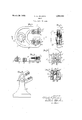
One form of device embodying my invention and in the construction and use of which the objects herein set out, aswell as others, may be attained, is illustrated in the accompanying drawings, in whichproved gauge.
Figure 2 is an end view of the gauge llus trating its operation.
Figure 3 is a view in section on a plane denoted by the dotted line 3-3 of Figure 1.
Figure 4 is a view, scale enlarged, illustrating the manner of mounting one of the described in such patent, the invention herein residing in certain details in construction of the mounting of several of the gauging elements of the device.
In the accompanying drawings the numeral 7 indicates the body or stock of my improved' gauge that is preferably of U.shape and having branches 8-9 that serve as supports for the gauging devices. The stock has an opening 10 and a groove 11 preferably concentric with the opening 10, said groove containing a designating plate 12 upon which `Figure l is a front face view of my im? 1924. Serial No. 708,725.
any desiredmarkings relating to the gauge may be placed. Removal plate holes 13 are formed through the stock from the back thereofin line with said groove so that by the insertion of an instrument through said holes the plate may be forced from its seat and replaced by another plate whenever desired, the plate fitting the groove tightly enough to enable it to be forced intov place and securely held therein by friction.
Each of the branches 8 and 9 is provided with ledges 14-15, the recessed faces or shelves of which are disposed below the plane of said branches, and a pair of gauging rollers 16 is mounted, oneY roller of said pair on each of said ledges. Likewise a pair of similarly formed back or guard rollers 17 is mounted, one roller of said pair on each of said rollers co-operating with each other in the gauging operation. Each of the rollersl is provided with a plurality of gauging ribs 18, that in the majority of cases,'though not all, are arranged in staggered relation, that is, the ribs of the rollers on one yof the branches re not in line with the ribs of the rollers on the other branch.
As above mentioned, the faces or shelves of the ledges constitute positioning surfaces for the gauging rollers, which. rollers are located adjacent to the walls or edges of the ledges. These Walls or edges of the ledges act as shields for the gauging rollers to protect such rollers from injury as by forcible contact with other elements. This continuous wall to act as a shield is preferred, but I anticipate that other forms of shields may be employed to protect the gauging rollers and prevent contact of foreign elements therewith.
Each of the rollers is mounted on a bearing in a hole in one of the ledges 14 or 15, and as shown in Figure 5 of the drawings, the body of the sleeve thereby being eccentric to said hole, and the reduced eccentrically arranged end of the sleeve providing a shoulder on the body resting upon the ledge. The outer end of the sleeve has a slot 20 by mea-ns of which it may be rotated. This end of the sleeve is i .xrnumber of ribs, but as these rollers-serve a Afunction as guard rollers to prevent passage headed providing a shoulder 21 resting against the bottom of a recess 22 in the end of the roller in which the sleeve is located, the distance between the under side of the head and the ledge being slightly greater than the distance from the bottom of the roller to the bottom of the recess 22 so that the roller may be rotated freely upon the bearing constituted by the body-of the sleeve. A fixedY bearing pin 23 is projected into the sleeve, said pin preferably having a head 24 resting against the outer surface of one of the branches 8'or 9, the inner end of the pin also preferably being threaded to receive a nut 25 located within a recess 26 in the sleeve 19, the end of the nut having a slot by means of which it may be turned and when turned into place against the bottom of the recess 26 the sleeve willbe held securely in place. When the nut isloosened by means of the slot therein, the
sleeve may be turned and the eccentricity of the body thereby provides means for changing the distance of the roller from a roller arranged on the opposite branch of the gauge'. Eachbf the rollers 16, in order to secure maximum results as to accuracy, is provided with a number of ribs 18, live being shown on the rollers herein, andthe rollers and ribs are so constructed that they may be engaged with threads on a device, as a bolt, close to the head 27 of such bolt, and in order to provide compactness of the tool and avoid undue projection of the rollers beyond the face of the tool, the ledges 14e-15 are provided whereby the rollers are so depressed that their outer ends jrise but a slight distance above such face.
The back rollers 17 may have any suitable of devices of improper -size that may have passed the rollers 16 it will be found that a less number of ribs may be employed than are used upon the gauging rollers 16, in the structure herein shown these guard rollers 17 having two ribs each. The several rollers shown herein are known in shop vernacular as go and no-go rollers 16v and 17, respectively.
After the gauge has been set'for any specific purpose the pieces to be gauged are pre sented to the -rollers 16 and if they pass between the rollers 16 and are stopped by the rollers 17 the pieces will be of proper size.
In order to adjust the rollers for any specific purpose the nut 25 is loosened and the sleeve 19 may then be turned by means of a screw driver in the slot 2O to locate the gauging or guard rollers in proper position with respect to each other and the nut 25 is then tightened to hold the parts securelyin place.
In order to determine the position of the sleeve 19 as to the eccentric portions thereof an indicating notch 28 is formed in the end of the head of thesleeve, and preferably midway between opposite ends of the slot 20, and as shown in Figures 1 and 4 of the drawings.
i In forming the gauge said notch will preferably be located at the point of greatest ec,
centricity of the sleeve, or opposite the point of least eccentricity of the sleeve, and in this way the exact position of the sleeve may be readily determined and it will then be apparent which way the sleeve may be turned to increase or decrease the space between the rollers. Means other than the indicating notch may be employed to denote the position of the eccentricity of the sleeve, in fact the slot 2O may be positioned with this end in view. In order that the rollers 16 may readily ade just themselves to proper positions to permit passage of a device of proper size being gauged and without binding or friction, the distance between the ledges 14 or 15 and the shoulder 21 hereinbefore referred to of a sleeve 19 is made enough greater than the distance between the lower end of the roller and the bottom of the recess 22, to enable the roller to have enough endwise play to adjust itself to the position of the threads and thus permit'the threads of a piece of proper size to readily pass.
A material feature of this invention resides in a set of go members constructed to correctly gauge elements, as forms, dimensions, etc., lengthwise of a screw and transversely of the thread, and a set of no go members constructed solely to engage elements crosswise of the screw and in the direction of depth of the thread. The go members of the gauge comprise a number of ribs extending along the members for a distance at least equal to the thickness of a threaded member, as a nut, to be engaged by the bolt, the threads on which are being cut, and preferably these ribs will extend for a distance somewhat greater than thatl mentioned. The go members being set to gauge a threadof a certain size, if having a lesser number of ribs than as just mentioned, might denote that a thread was being perfectly formed, but upon the insertion of the bolt in the nut designated for it, it would be found that the bolt would not enter entirely through the nut. This is for the reason that the ribbed portion of short dimension either engaged only a perfect portion of the thread of the bolt, or perhaps a defect so minute as that the gauge would permit it to pass. This minute defect, however, occurring at intervals along the thread would multiply the defect vsuiiciently to prevent passage of the bolt between the gauging members if the gauging Lribs engaged the i thread for a substantial part of its length.
` Therefore, it is material that the ribbed portions of the gauging members be' of a length sufficient to certainly detect any vital defects in the thread, thereby rendering the latter faultyvso far asv elements extending lengthwise of a bolt are concerned.
The gauging members being correctlyv set tov I gauge afthread of a certain size, if it be found CII ' its lesser diameter may 'now be too small, and
perfectly formed might be erroneously conthat the bolt being threaded will not pass the the. plane of the corresponding face of its go set o f members, it is permissible, within branch, a gauging member mounted on one certain defined limits, to make the bolt smallledge and having thread engaging ribs exer in diameter. This being done sufficiently tending around the periphery thereof, an opto enable a .bolt to pass the go members of posing gauging member on the other ledge,
the gauge would determine that such bolt will and means providing. a relative adjustment engage the threadsof a nut for which it is inbetween the said gauging members toward tended, and therefore that the bolt has been and from each other.
3. A gauge comprising a stock having opposed branches located in spaced relation, a 75 gauging member, elongated mounting means or said member supported solely at one end this would not be determined by the go in one of the branches and including a por-` members. Theno"go members of the gauge tion in the-branch relatively eccentric to the now become essential. Containing a small member mounting portion outside the number of ribs, one, or two at the most, they branch, rotation ojf the said portion in the will not check errors as to elements lengthbranch being adapted to adjust the said memwise of the thread but willcheck them crossber toward and from the other branch, means wise of the bolt or in the direction of depth passing through the mounting means for reof the thread only, and preferably errors as taining the latter in adjusted position, and to size in diameter. If the bolt being formed an opposing gauging member located on the eluded.
This, however, is not so, as the -bolt Iwith is too small in diameter, this', not having other branch.
been determined by the go members of the 4. A gauge comprising a stock having opgauge, will beindicated by the fno go memposed branches located in spaced relation, a bers of the gauge. If the -bolt will pass be'- gauging roller, a one-piece member sup- 90 vtween the no go members, itis too small in ported solely at one end in one of said diameter, although the gof members have branches and having a relatively eccentric indicated that it was correct in other respects. portion extending outwardly therefrom and It is therefore material that the go memsupporting the roller thereon, rotation of bers shall be composed of a large number of the member being adapted to adjust the ribs to checkfaccuracy as to elements extendroller toward and from the other branch, ing lengthwise of the bolt and that the no means concentric to the gauging roller for go members shall consist of one, or at most retaining said member in adjusted position, two ribs, to check inaccuracies solely as to and an opposing gauging member on the elements crosswise of the bolt, as of diameter. other branch.v
As a convenient means for holding the i5. A screw thread gauging tool comprisgauge for gauging operations I have proing a stock with branches extending therevided a standard 29 that is forked at its upper from in spaced relation, an elongated bearend to receive the gauge, and as shown in Fig/ing member secured at one end to one of said ure 6 of the drawings, a clamp bolt 30 being branches and having its opposite end unsup- 195 employed to secure the gauge in proper posiported, a gauging member mounted on said tion. bearing member and having thread engaging In accordance with the provisions of the ribs extending around the outside thereof, patent statutes I have described the princimeans for retaining saidl gauging member ples of operation of my invention together on said bearing member, and means passing with the device which I now consider to repthrough the. bearing member for fastening resent the best embodiment thereof; but I dethe latter to its branch. sire to 'have it understood that the device 6. A screw thread gauging tool comprisshown is only illustrative, and that the ining a stock with branches extending therevention may be carried out by other `means lfrom in spaced relation, a bearing sleeve seand applied to uses other than those above cured at one end to one of said branches and set out. having a shouldered head at its other end, a Iclaimgauging roller mounted on the sleeve and 1. A gauging tool comprising a stock with having a recess to receive said head and a opposed branches extending therefrom in shoulder underlying the shoulder on the spaced relation, ledges formed on the facing head, and means housed substantially enedges of said branches and each ledge havtirely within the sleeve for securing said ing its face depressed below the plane of the sleeve in place. I corresponding face of its branch, and gaug- 7. `A screw thread gauging tool comprising\n ing members mounted on said ledges. a stock with branches extending therefrom in "2 2. A thread gauging tool ,comprising a spaced relation, a ledge formed on the inner stock with opposed branches extending edge of one of said branches and having its y therefrom in spaced relation, ledges formed face depressed below the plane of the correon the facing edges of said branches and sponding face of the branch, a headed gauge each ledge having its face depressed below member support secured at one end to said 3C ledge and projecting therefrom with its opposite end unsupported and extending only a short distance beyond said corresponding face of its branch, and a gauging member mounted upon said support and having a recess in one end to receive the head of said support by means of which themember is secured in place.
8. A screw thread gauging tool comprising a stock with branches extending therefrom in spaced relation, a pair of headed gauge roller supports each secured at one end to theA same one of said branches and projecting therefrom with their opposite ends unsupported, gauging members mounted on said supports, one gauging member being piovided with a different number of thread engaging elements from the other thread en-A gaging member, said members being adjustroller being provided with a closely adjacent pair of annular ribs extending circumferentially'around its periphery, said rollers being adjustable toward cooperating gauging members mounted in the opposed branch.
l0. A screw thread gauging tool comprising a stock with bianches extending therefrom in spaced relation, a bearing member mounted on one of said branches and including a bearing portion for a gauging member,
. said bearing member being rotatably adjustably connected to its supporting branch by an eccentric journal, means concentric with theA said bearing portion for retaining the bearing member in adjusted position, said bearing member having a tool engaging portion for accomplishing adjustments and an indexing mark visible with a tool in place to denote the eccentric position of the bearing member, and a gauging member mounted on said bearing portion.
11. A screw thread gauging tool comprising a stock with branches extending therefrom in spaced relation, a bearing sleeve mounted on one of said branches and having a portion arrangedl eccentrically with respect thereto and including a roller bearing portion, said bearing and sleeve having a recess therein and being rotatably adjustably connected to its supporting branch by said eccentrically arranged portion, a screw threaded A-pin passing through said branch and extending into said sleeve and having a head resting against said branch, a nut tting the screw threaded end of said pin and located in said recess, and a gauging roller rotatably mounted on said sleeve.
12. A screw thread gauge comprising a plurality of pairs of thread gauging members, each member having cooperating thread gauging elements, one pair of said members having a relatively large number of said thread gauging elements, and the other pair having two closely adjacent thread gauging elements.
13. A screw thread gauge comprising a plurality of sets of thread gauging members, each ot said members having cooperating thread gauging elements, one of said sets having circular thread gauging ribs extending over a length at least equal to the length of the threads being gauged, and another of said pairs having` not more than two thread gauging ribs on each member thereof.
14. A screw thread gauge comprising a plurality of sets of thread gauging members, each gauging member having a plurality of thread gauging elements, one of said sets having a relatively large number of thread gauging elei ents, and the other having not more than two'ot' said thread gauging elements, onemember of each pair being adjustable to vary the distance between the members of each pair.
l5. A screw thread gauge comprising a supporting frame, supports secured at one end only to said frame and projecting therefrom, sets of screw thread gauging members mounted on said supports, each of said thread gauging members having thread gauging elements thereon, one pair of said members having a relatively large number of said elements, and the other pair of said elements having relatively few closely adjacent gauging elements.
16. A gauging tool comprising a stock with opposed branches extending therefrom in spaced relation, supports secured at one end in said branches, the other ends of the sup- ,ports being unsupported, gauging members mounted on said supports, and shields located on said branches to' prevent contact of foreign elements with said gauging members at the sides opposite the facing edges of said branches.
17. A screw thread gauging tool compris- :ing a stock with branches extending therefrom in spaced relation, one of said branches having a hole therein, a shouldered gauging member support secured in said hole with its shoulder resting against the face of said branch, the opposite end of said support being unsupported, a gauging member mounted on said support, and a cooperating gauging member on the opposite branch.
CHAS. G. JOHNSON.
Priority Applications (1)
| Application Number | Priority Date | Filing Date | Title |
|---|---|---|---|
| US708725A US1851283A (en) | 1924-04-24 | 1924-04-24 | Gauge |
Applications Claiming Priority (1)
| Application Number | Priority Date | Filing Date | Title |
|---|---|---|---|
| US708725A US1851283A (en) | 1924-04-24 | 1924-04-24 | Gauge |
Publications (1)
| Publication Number | Publication Date |
|---|---|
| US1851283A true US1851283A (en) | 1932-03-29 |
Family
ID=24846944
Family Applications (1)
| Application Number | Title | Priority Date | Filing Date |
|---|---|---|---|
| US708725A Expired - Lifetime US1851283A (en) | 1924-04-24 | 1924-04-24 | Gauge |
Country Status (1)
| Country | Link |
|---|---|
| US (1) | US1851283A (en) |
Cited By (4)
| Publication number | Priority date | Publication date | Assignee | Title |
|---|---|---|---|---|
| US2436528A (en) * | 1944-11-10 | 1948-02-24 | Sheffield Corp | Screw thread gauge |
| US2443820A (en) * | 1943-10-25 | 1948-06-22 | Gabbey Eric Gordon Douglas | Gauge for measuring or checking the effective diameters of screw threads |
| US2515418A (en) * | 1946-06-29 | 1950-07-18 | Niles Bement Pond Co | Gauge for small screw threads |
| US2849804A (en) * | 1955-03-15 | 1958-09-02 | Johnson Gage Dev Company | Thread gage having gaging rolls with setting surfaces |
-
1924
- 1924-04-24 US US708725A patent/US1851283A/en not_active Expired - Lifetime
Cited By (4)
| Publication number | Priority date | Publication date | Assignee | Title |
|---|---|---|---|---|
| US2443820A (en) * | 1943-10-25 | 1948-06-22 | Gabbey Eric Gordon Douglas | Gauge for measuring or checking the effective diameters of screw threads |
| US2436528A (en) * | 1944-11-10 | 1948-02-24 | Sheffield Corp | Screw thread gauge |
| US2515418A (en) * | 1946-06-29 | 1950-07-18 | Niles Bement Pond Co | Gauge for small screw threads |
| US2849804A (en) * | 1955-03-15 | 1958-09-02 | Johnson Gage Dev Company | Thread gage having gaging rolls with setting surfaces |
Similar Documents
| Publication | Publication Date | Title |
|---|---|---|
| US1851283A (en) | Gauge | |
| US2501130A (en) | Gauge for checking external dimensions of circular work | |
| US1908253A (en) | Gauge | |
| US2079323A (en) | Work holder for machining operations | |
| US3319339A (en) | Multi-height comparator and gauge | |
| US2406514A (en) | Roll v block support | |
| US2541821A (en) | Micrometer | |
| US2941303A (en) | Universal locating fixture | |
| US2702946A (en) | Dial bore gauge | |
| US2397492A (en) | Machinist's gauge | |
| US2367255A (en) | Gauging device | |
| US2326562A (en) | Precision square | |
| US2249611A (en) | Internal thread gauge | |
| US2105054A (en) | Gauge for measuring angles | |
| US3983633A (en) | Lead checking gage | |
| US2494715A (en) | Sine bar | |
| US2724186A (en) | Adjustable micrometer caliper | |
| US2370503A (en) | Gauging device | |
| US2436528A (en) | Screw thread gauge | |
| US2399624A (en) | Thread diameter gauge | |
| US3210855A (en) | Center-finding device | |
| US3367032A (en) | Keyway and like gage | |
| US3112659A (en) | Interchangeable head boring bar | |
| US4317997A (en) | Positioning fixture for measuring instruments | |
| US2444702A (en) | Multiple diameter gauge |