US1851269A - Inside casing cutter - Google Patents
Inside casing cutter Download PDFInfo
- Publication number
- US1851269A US1851269A US496150A US49615030A US1851269A US 1851269 A US1851269 A US 1851269A US 496150 A US496150 A US 496150A US 49615030 A US49615030 A US 49615030A US 1851269 A US1851269 A US 1851269A
- Authority
- US
- United States
- Prior art keywords
- sleeve
- mandrel
- slip
- extension
- followers
- Prior art date
- Legal status (The legal status is an assumption and is not a legal conclusion. Google has not performed a legal analysis and makes no representation as to the accuracy of the status listed.)
- Expired - Lifetime
Links
- 230000006835 compression Effects 0.000 description 3
- 238000007906 compression Methods 0.000 description 3
- RUPBZQFQVRMKDG-UHFFFAOYSA-M Didecyldimethylammonium chloride Chemical compound [Cl-].CCCCCCCCCC[N+](C)(C)CCCCCCCCCC RUPBZQFQVRMKDG-UHFFFAOYSA-M 0.000 description 2
- 241000837181 Andina Species 0.000 description 1
- XUKUURHRXDUEBC-KAYWLYCHSA-N Atorvastatin Chemical compound C=1C=CC=CC=1C1=C(C=2C=CC(F)=CC=2)N(CC[C@@H](O)C[C@@H](O)CC(O)=O)C(C(C)C)=C1C(=O)NC1=CC=CC=C1 XUKUURHRXDUEBC-KAYWLYCHSA-N 0.000 description 1
- HSRJKNPTNIJEKV-UHFFFAOYSA-N Guaifenesin Chemical compound COC1=CC=CC=C1OCC(O)CO HSRJKNPTNIJEKV-UHFFFAOYSA-N 0.000 description 1
- 229910000760 Hardened steel Inorganic materials 0.000 description 1
- 241001417524 Pomacanthidae Species 0.000 description 1
- 101150111878 Vegfd gene Proteins 0.000 description 1
- 229960001948 caffeine Drugs 0.000 description 1
- 238000005553 drilling Methods 0.000 description 1
- 239000000463 material Substances 0.000 description 1
- 102220112880 rs370986101 Human genes 0.000 description 1
- RYYVLZVUVIJVGH-UHFFFAOYSA-N trimethylxanthine Natural products CN1C(=O)N(C)C(=O)C2=C1N=CN2C RYYVLZVUVIJVGH-UHFFFAOYSA-N 0.000 description 1
- CEWNUSPMSSUSJA-AATRIKPKSA-N ustin Chemical compound O1C(=O)C2=C(C)C(Cl)=C(O)C(Cl)=C2OC2=C(Cl)C(C(/C)=C/C)=C(O)C(C)=C21 CEWNUSPMSSUSJA-AATRIKPKSA-N 0.000 description 1
Images
Classifications
-
- E—FIXED CONSTRUCTIONS
- E21—EARTH OR ROCK DRILLING; MINING
- E21B—EARTH OR ROCK DRILLING; OBTAINING OIL, GAS, WATER, SOLUBLE OR MELTABLE MATERIALS OR A SLURRY OF MINERALS FROM WELLS
- E21B29/00—Cutting or destroying pipes, packers, plugs or wire lines, located in boreholes or wells, e.g. cutting of damaged pipes, of windows; Deforming of pipes in boreholes or wells; Reconditioning of well casings while in the ground
- E21B29/002—Cutting, e.g. milling, a pipe with a cutter rotating along the circumference of the pipe
- E21B29/005—Cutting, e.g. milling, a pipe with a cutter rotating along the circumference of the pipe with a radially-expansible cutter rotating inside the pipe, e.g. for cutting an annular window
Definitions
- This invention relates 'toa'classvo'f tools 5 used in well drilling known as insidef casing ,Y cutters andinas 4for its principallobject to d l-si'mpliiiyand irnprove theconstruetion there- -More. ⁇ sp,eciically, this,y vinvention relatestov thejtypejof casingfcutter carrying a cutting blade-or knife hinged-on asleeverandfadvanced toi' operativeor ycutting position by 12 is an extension/thereof markedfl.
- ly'theV cutting c knives being'shown in advanced or operating y-position ⁇ Figs ⁇ 3 and; 43 are sections on an enlargedl scalea's seen on the,correspondinglyy ⁇ v.'10' numbered lines o;t"Fig gf.pg1;ll1"ig.f 5fis a'detail viewof?
- one ofthe-lugs connecting the 'sleeve Y' Vfand thernandrel and Figf isa .section on Y anenlal'gil SCaleas seen 'onfline of i "t5 Referring rIn*ore'f*particularity.
- Y 'A skirt ⁇ l() depends frointhe f subfandhas a sleeve ll secured toits lower end Aany "con, venient”A manner.; Slidable y K "withinsleeve gll is aspreader InandrelVlQ $5 whichis provided withwrecesses 14g-'while ng'ers” orlugsy I5-orrned on the ysleevell are adapted to engage lthese recesses, thereby 1 Y ipeirnittingrelative 'axial ni'ovement of the v sleeve" and the mandrel butv preventing rela-i 5 '55.01 tive rotary movement between thenf Intermediate recesses 14 in thefma'ndrel are formed 'guideways 16 and pivotally attached to sleeveV 11 so" as toL register Vtherewith are cutting v' knives ⁇ The guidewaysand knives are sol y arranged
- YSlida'bly"secured'tothe'slip I bodyA by-*thefusual dovetail arrangement-7 are lslips 31; slip rods 32Y serving to .Connect thein s to the lowery spring followers.
- slip rods 32Y serving to .Connect thein s to the lowery spring followers.
- the ⁇ casingfcutter is opjeratedin thefollowing manner: It is lowered ⁇ in the casing untilthe point isieachedwhere itjis desiredy tomake a cut', and there givenza'fewgturn's' in f a ,right handA direction, thefspring followers,
- n .AtiV the Vbottom of recesses 14 are set screws 34 which may be adjusted as to their ⁇ pr action above the bottom of the -recesses im locked in position by lock nuts 35.
- the y fingers abutthe screws34and-limit the longitudinal movement of sleeve 11 with respcct to mandrel 12. This movement determines the projection of the knives 17.
- the amount of projecl" tion of the nives will be determined.
- a casingy cutter comprising a sleeve, a
- said shaft dependlng from said sleeve, a mandrel slidable in the sleeve and. on the shaftand p baving'cutter guide-ways, saidmandrel ⁇ besaid slip mechanism comprising a slip actuf extension.
- a casing cutter comprising a sleeve, a shaft Adepending from said sleeve, a mandrel slidable axially and non-rotatable in the sleeve and on the shaft and having cutter guide-ways; pivoted cutters carried by the sleeve and disposed in position opposing the guide-ways of said mandrel whereb the cutters coact with the surfaces of said guideways yto cause ,projection of said cutters; a. depending extension on said mandrel encompassing said shaft, a slip ism fortzusing sliding of said mandrel in said' sleeve;
- ator including spaced spring followers slidably mounted on said extension, bowed springs connecting said followers; a sl' body slidable on said extension and dintermediate' the followers, there being an abutment on said extension for engagement by said slip body in its upward movementgslips yriding on said slip body and'coupled te said actuator, and releasable meansfto restrain movementrof said slip mechanism in said 3.
- a casi cutter comprising a sleeve, a shaft depending from said sleeve, a mandrel axially slidable and nonfrotatable inthe sleeve and on the shaft and havin cutter guide-ways; pivoted cutters carri by the sleeve and dis osed in position opposing the guide-ways o said mandrel whereb upon inward projection of said mandrel t cutters coact with the surfaces of said guideways to cause projection of said cutters; a compression spring insaid sleeve acting on yand tending to project said mandrel, ,a depending extension on said mandrel, a slip mechanism for causing sliding of said mandrelin said sleeve and shaft; said slip mech-y anism comprising a slip actuator including spaced spring followers slidably mounted on said extension, bowed springs connecting said followers; a slip body slidable on said extension and disposed intermediate the followers,fthere being an
Landscapes
- Life Sciences & Earth Sciences (AREA)
- Engineering & Computer Science (AREA)
- Geology (AREA)
- Mining & Mineral Resources (AREA)
- Physics & Mathematics (AREA)
- Environmental & Geological Engineering (AREA)
- Fluid Mechanics (AREA)
- General Life Sciences & Earth Sciences (AREA)
- Geochemistry & Mineralogy (AREA)
- Confectionery (AREA)
Description
,ParenmiA Man-129. 1932 f. f f
nAYMoND ,A,Nniarinn'` for ooinrrom cALrroRNIA, Assrenon 'ro QKYRAD," .on vLos@Y ANGELES, *C11 lLIEYIRNDES7 .AfCORPQRATION.;OFCALIFORNIA. ,f
` iNsInEcnsINe Y 'npgneatiqe kineanwv-einher ieaafs'ferial 6,150. 'Y
,Y .This inventionrelates 'toa'classvo'f tools 5 used in well drilling known as insidef casing ,Y cutters andinas 4for its principallobject to d l-si'mpliiiyand irnprove theconstruetion there- -More.`sp,eciically, this,y vinvention relatestov thejtypejof casingfcutter carrying a cutting blade-or knife hinged-on asleeverandfadvanced toi' operativeor ycutting position by 12 is an extension/thereof markedfl. x Se'- cured tonthepftopof the 'mandrelis a Astop v, e ring 20 adapted to'engage the upper end kof l sleeve-All and liinit the upper -niovementj'of the sleeve alengthej mandrel," In the; space lwithin skirt 110 isa #compression spring 21j normallyholding'stop ring 20fagainst the upit m slidinga spreader within the sleeve, nand has yforl 'another object; to; provide an yimproved f `mean`s kof mountin'gfandf advancing V'the,
hinged blade. n i l. Y p Y j Another object offthis invention istc pro- 15 vide alfformv of 4casinofcutter lwhi'chinay be y yof" small external. diameter, l y
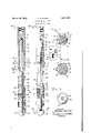
i4The object together Withother objects and corresponding accomplishments are obtained Vby' means of the embodiment of my invention A f@ rimmed inthe' accompanying drawings in piwhiclr;` i Fggfl symainly anaxal section oit my iil- A :proved casingfouttenN certain partsbeingi j *shown inelevat1o:n,and the cutting knivesv 7:5, being retracted to inoperative position ;"-,Fig. V2-lis avie'w" similarvkto F ig. ly'theV cutting c knives being'shown in advanced or operating y-position{Figs} 3 and; 43 are sections on an enlargedl scalea's seen on the,correspondinglyy` v.'10' numbered lines o;t"Fig gf.pg1;ll1"ig.f 5fis a'detail viewof? one ofthe-lugs connecting the 'sleeve Y' Vfand thernandrel and Figf isa .section on Y anenlal'gil SCaleas seen 'onfline of i "t5 Referring rIn*ore'f*particularity. `to the "drawingsf8i indicates a sub4 internally *threaded atiitsu'pper end for engagement I withtheend ofV the fishing'string'.A l'port 9"per'mits' y,the circulation iiuid to vpass-'frein i '40 Ast heflshing string" out into thespaoesurrond ing thetool. Y 'A skirt `l() depends frointhe f subfandhas a sleeve ll secured toits lower end Aany "con, venient"A manner.; Slidable y K "withinsleeve gll is aspreader InandrelVlQ $5 whichis provided withwrecesses 14g-'while ng'ers" orlugsy I5-orrned on the ysleevell are adapted to engage lthese recesses, thereby 1 Y ipeirnittingrelative 'axial ni'ovement of the v sleeve" and the mandrel butv preventing rela-i 5 '55.01 tive rotary movement between thenf Intermediate recesses 14 in thefma'ndrel are formed 'guideways 16 and pivotally attached to sleeveV 11 so" as toL register Vtherewith are cutting v' knives `The guidewaysand knives are sol y arranged'withres'pect to eachother that when? the sleeve is moved downward'overf the man# drelthe knives 'willbe projected te -cutting A position (seeY Fig.y 2).
' `Secured to kthe lwer -en'd of the mandrel per Vend ofy theisleevel 'VSecured -to`sub 8 and slidable withinfabore through mandrel V"lower end. n
#Slidable and rotatable onextensiori nian-l Y drelflQ are'upper andlowerspring followersk 24' and'25, joined b'ybowedsprings 26: l kThe Ql'wer? spring follower 25 is'threadedlyl" er1- f'gaged by releasefnut;wheiitfis not. desired Ito-projectthecutting knives v17 -Ytsee Figi 1 astopgtooth 27 beingprovided to 'prevent the Y j rthrefadsfbeing too 4tightlyengaged',l inf amannerv well understoofd.A ."Also vslidable .and 'io-'- 'tatable upennV ni'andrel Vextension 19 between the `spring followers isa slip body'28,'^whofse 'longitudinal movement-.is {liinited by Astop 'ring 29'sec1`1red tothe mandrel'extensionand an vannular shoulder 30 :torniedjon'thejinan drei extension. YSlida'bly"secured'tothe'slip I bodyA by-*thefusual dovetail arrangement-7 are lslips 31; slip rods 32Y serving to .Connect thein s to the lowery spring followers.' 1 Between'the-` j f annularjshoulderSOjand the slip body ,'28 is afp'air'i of race rings v33 ,which vare ofrfsorne wear resisting material such as hardened steel yand areto prevent wear of the slipbody and annular. shoulder,l as `willbe later apparent. The` casingfcutter is opjeratedin thefollowing manner: It is lowered `in the casing untilthe point isieachedwhere itjis desiredy tomake a cut', and there givenza'fewgturn's' in f a ,right handA direction, thefspring followers,
slips and COnneCtedparts being held stationary by the drag of the bowed springs on the casing. This disengages the lower spring follower 25 from the release nut 23. Shaft 22, mandrels 12 and 19, and sleeve 11 are now lowered further until annular shoulder 30 engages slip body 28 (race rings 33 of course being'k interposed). The bowed springs, spring followers and slips being maintained approximatel stationary by the drag of the misprings on t e casing, further downward movement of mandrel extension 19 will force the slip` body between the slips 31, the taper of the body forcing them into engagement with the casing. This prevents furtherdownward movement of mandrels 12 and 19. The
i mandrels 1-2 and L19V, shaft 22 and sleeve 11,
vhave, all been maintained in the relationship shown in Fig. y1 by spring 21. Mandrels 12 'f and 19 being now held against further downl go, ward movement, continued downward move- Ament Vof the fishing string will compress ,spring 21 and move sleeve 11 downwardly relative to mandrel 12. This will force the cutting knives 17 outwardly along the guideg5, lways y16 to operative or cutting position in cony toet withv'the casing and all parts will then be as shown in Fig. 2. The tool is now rotated by means of the fishing string, knives 17 making an annular cut in the casing. As
- so j slip body 28 is maintained stationary kwhile the mandrels and kconnected parts are rotated and considerable axial pressure is exerted between them, some replaceable means to take l the, wear, as race rings 33, are necessary.
.46: Aitor the cut has been completed, upward movement of the fishing string will return mhndiols 12 and 19 andsleeve 11 to their initial positions, and cutting knives 17 will drop back to, inoperative position by their 40 own weight. Further, upward movement will ,move the slip body up relative the slips which v 'will disengage them rfrom the casing and allow the casing cutter to be moved uy in the Release nut: 23` lmay be rep aced in f of the drill string to the left. AAll parts are now in theiroriginal positions as shown in V1, the tool may be moved up'or down, a anothercutcan be made in the casing at "0 adesired point. Y f p,
n .AtiV the Vbottom of recesses 14 are set screws 34 which may be adjusted as to their `pr action above the bottom of the -recesses im locked in position by lock nuts 35. The y fingers abutthe screws34and-limit the longitudinal movement of sleeve 11 with respcct to mandrel 12. This movement determines the projection of the knives 17. Thus, by adj ustin screws 34,the amount of projecl" tion of the nives will be determined. f
What I claim is y L A casingy cutter comprising a sleeve, a
shaft dependlng from said sleeve, a mandrel slidable in the sleeve and. on the shaftand p baving'cutter guide-ways, saidmandrel` besaid slip mechanism comprising a slip actuf extension.
spring follower if desired by a few turns .ing coacting means whereby to releasably lock said slip mechanism against sliding 9 movement on said extension. a
2. A casing cutter comprising a sleeve, a shaft Adepending from said sleeve, a mandrel slidable axially and non-rotatable in the sleeve and on the shaft and having cutter guide-ways; pivoted cutters carried by the sleeve and disposed in position opposing the guide-ways of said mandrel whereb the cutters coact with the surfaces of said guideways yto cause ,projection of said cutters; a. depending extension on said mandrel encompassing said shaft, a slip ism fortzusing sliding of said mandrel in said' sleeve;
ator including spaced spring followers slidably mounted on said extension, bowed springs connecting said followers; a sl' body slidable on said extension and dintermediate' the followers, there being an abutment on said extension for engagement by said slip body in its upward movementgslips yriding on said slip body and'coupled te said actuator, and releasable meansfto restrain movementrof said slip mechanism in said 3. A casi cutter comprising a sleeve, a shaft depending from said sleeve, a mandrel axially slidable and nonfrotatable inthe sleeve and on the shaft and havin cutter guide-ways; pivoted cutters carri by the sleeve and dis osed in position opposing the guide-ways o said mandrel whereb upon inward projection of said mandrel t cutters coact with the surfaces of said guideways to cause projection of said cutters; a compression spring insaid sleeve acting on yand tending to project said mandrel, ,a depending extension on said mandrel, a slip mechanism for causing sliding of said mandrelin said sleeve and shaft; said slip mech-y anism comprising a slip actuator including spaced spring followers slidably mounted on said extension, bowed springs connecting said followers; a slip body slidable on said extension and disposed intermediate the followers,fthere being an abutment on said extension for engagement b said slip body in its upward movement; s ipsriding 0n said slip `body and coupled to said actuator, and releasablemeans at the foot of said shaft for l Herrlgxgng*`tlieflo'vver follower to restreinmove- Y Y Inent ofrsad Aslip mechanism on -sailezdiel-` 's10n. l 4. A'caysing cutterY comprising@ sleeve', a
v 1,851,269A f shaft dependingV frolnsaid sleeve; a,V mandrel sldablein the A,sleeve and on the Shaft and f having, cutter guide-Ways ;Q.pivoted"f cutters Y carried by the Sleeveand Vdisposedin posi`V tion opposingthe guide-Ways, of'sai'd mandrel whereby upon inward projection of said mandrel the cutters coa'etfwth the surfaces of said` v guide-'ways tocause projection of 'said cut- A v f ters; compression Sprngrfn' said'sleeve @cti ing on Aand,tending. to project saidmndrel, depending extension on saidmandrelfenj, A compaspsin'g saidshaft,v a slip mefcl'lalllsml for Y 'causing' sldingofsaidmandreln'saidsleeve anda releselnut fattheootof'saidrshaft; f, said-.slip vmechanismfcomprising,:spaced v Spring followers; slidably f mounted on. Said" eXtenson,-bowed springs connectng'saidfolf l lowers; a slip body sld'ab'le on's'aid extension n and Adisposed lkltelfmediete'*the,Yfollorels,u f "i Y there b'e'nglan abutmentonsedextension.
l '25, Y -V Wardymoyement; slips 'riding .on saidfs'lip bodyand coupled to one of;,sald';followersa the lower of Said; followers having ythreeuyls v 1' ,l for engagement'fwth the thnead'sfof Saidjreleasenut-- 1 l ,c In 'witness thatfl Claimfythef/foregoingl n eunto'Sbscrbedfnlynallieithsfth Y.
for engagement by Saidy "slpgbody" yin its iup# have her n by l Vsov
Priority Applications (1)
| Application Number | Priority Date | Filing Date | Title |
|---|---|---|---|
| US496150A US1851269A (en) | 1930-11-17 | 1930-11-17 | Inside casing cutter |
Applications Claiming Priority (1)
| Application Number | Priority Date | Filing Date | Title |
|---|---|---|---|
| US496150A US1851269A (en) | 1930-11-17 | 1930-11-17 | Inside casing cutter |
Publications (1)
| Publication Number | Publication Date |
|---|---|
| US1851269A true US1851269A (en) | 1932-03-29 |
Family
ID=23971456
Family Applications (1)
| Application Number | Title | Priority Date | Filing Date |
|---|---|---|---|
| US496150A Expired - Lifetime US1851269A (en) | 1930-11-17 | 1930-11-17 | Inside casing cutter |
Country Status (1)
| Country | Link |
|---|---|
| US (1) | US1851269A (en) |
Cited By (2)
| Publication number | Priority date | Publication date | Assignee | Title |
|---|---|---|---|---|
| US2764812A (en) * | 1954-06-28 | 1956-10-02 | Airetool Mfg Company | Inside tube cutter, particularly for heat exchangers and the like having tubes of small diameter |
| US3061012A (en) * | 1959-08-31 | 1962-10-30 | Johnston Testers Inc | Well packers |
-
1930
- 1930-11-17 US US496150A patent/US1851269A/en not_active Expired - Lifetime
Cited By (2)
| Publication number | Priority date | Publication date | Assignee | Title |
|---|---|---|---|---|
| US2764812A (en) * | 1954-06-28 | 1956-10-02 | Airetool Mfg Company | Inside tube cutter, particularly for heat exchangers and the like having tubes of small diameter |
| US3061012A (en) * | 1959-08-31 | 1962-10-30 | Johnston Testers Inc | Well packers |
Similar Documents
| Publication | Publication Date | Title |
|---|---|---|
| US2110913A (en) | Pipe cutting apparatus | |
| US3220478A (en) | Casing cutter and milling tool | |
| GB716761A (en) | Improvements in or relating to drill assemblies | |
| US2464390A (en) | Oil well casing scraper | |
| US2238609A (en) | Pressure core barrel | |
| US1851269A (en) | Inside casing cutter | |
| US2258052A (en) | Spiral guide and tubing holder | |
| US2101968A (en) | Jar | |
| US2299528A (en) | Casing mill | |
| US1765864A (en) | Trip casing spear oil-well rotary fishing tool | |
| US2204091A (en) | Inside pipe cutter | |
| US2116903A (en) | Expansible cutter tool | |
| US1996132A (en) | Deep well drilling and coring system | |
| US1779652A (en) | Apparatus for perforating well casings | |
| US2208011A (en) | Inside tubing cutter | |
| US2167739A (en) | Cut indicator for casing cutters | |
| US3186489A (en) | Retrievable plugs and packers for deep wells | |
| US2202985A (en) | Pipe cutter | |
| US2108330A (en) | Pipe cutter | |
| US1839767A (en) | Drilling apparatus | |
| US2117594A (en) | Inside casing cutter | |
| US1862629A (en) | Well drill | |
| US3080241A (en) | Outside pipe-cutting tool | |
| US2351187A (en) | Pipe cutter | |
| US2158243A (en) | Casing cutter |