US1851264A - Adjusting device for cigarette machines - Google Patents
Adjusting device for cigarette machines Download PDFInfo
- Publication number
- US1851264A US1851264A US523553A US52355331A US1851264A US 1851264 A US1851264 A US 1851264A US 523553 A US523553 A US 523553A US 52355331 A US52355331 A US 52355331A US 1851264 A US1851264 A US 1851264A
- Authority
- US
- United States
- Prior art keywords
- wheel
- tape
- shaft
- machine
- hand
- Prior art date
- Legal status (The legal status is an assumption and is not a legal conclusion. Google has not performed a legal analysis and makes no representation as to the accuracy of the status listed.)
- Expired - Lifetime
Links
- 235000019504 cigarettes Nutrition 0.000 title description 24
- 230000008878 coupling Effects 0.000 description 11
- 238000010168 coupling process Methods 0.000 description 11
- 238000005859 coupling reaction Methods 0.000 description 11
- 230000007246 mechanism Effects 0.000 description 10
- 238000010276 construction Methods 0.000 description 6
- 238000010516 chain-walking reaction Methods 0.000 description 4
- 230000000694 effects Effects 0.000 description 2
- 238000007789 sealing Methods 0.000 description 2
- 238000000034 method Methods 0.000 description 1
Images
Classifications
-
- A—HUMAN NECESSITIES
- A24—TOBACCO; CIGARS; CIGARETTES; SIMULATED SMOKING DEVICES; SMOKERS' REQUISITES
- A24C—MACHINES FOR MAKING CIGARS OR CIGARETTES
- A24C5/00—Making cigarettes; Making tipping materials for, or attaching filters or mouthpieces to, cigars or cigarettes
- A24C5/14—Machines of the continuous-rod type
- A24C5/31—Machines of the continuous-rod type with special arrangements coming into operation during starting, slowing-down or breakdown of the machine, e.g. for diverting or breaking the continuous rod
Definitions
- This invention relatesto tape drives for continuous rod cigarette machines, its object being vto provide a device for conveniently turning the machine .over by lhand as well as for separately adjusting the tape wheel without disturbing thefadjustment of any other part of the machine.
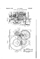
- Fig. l is a front elevation of a portion of a continuous rod cigarette machine, showing the tape wheel drive equipped with the improved adjusting device; and i Fig., 2 is a sectional slide elevation of the adjusting, mechanism on lines 2-2 of Fig. 1.
- Atape wheel of afcontinuous rod cigarette machine manually operable means operative only when the machineis stoppedV for turning said' machine and tape wheel'in the forward direction only, and manually operable mechanism independent of said means for turning the tape wheel in either direction.
- said means includes the 'main drive shaft of the machine, a gear loosely mounted ,on the driveshaft, a hand-wheel .geared to said gear, a one-way clutch between the gear and the drive shaft, gearing between the drive shaft and the tape wheel shaft, sprockets on the tape wheel shaft and the hand-wheel shaft, a chain running Aover said sprockets, a one-way clutch'betweengsaid tape wheel way clutch between said gearing and said tape wheel sprocket.
- said mechanism includes a handwheel spacedV from the f tape wheel handwheel andgeared' tothe tape wheel and a device Vfor disengaging the one-wayr clutch sprocket and tape wheel shaft, and a one-v the scope of the claims, for the particular machine selected to illustrate the invention is but one of many possible concrete embodiments of the same. The invention, therefore, is not to be restricted to the specific construction shown and described.
- C is a cigarette rod propelled through the rod forming and sealing mechanisms of a continuous rod cigarette machine by the endless tape belt T running over the tape wheel 3 on shaft 4 which is driven by a worm wheel 5 meshing with a worm 6 on the drive shaft 7 of the cigarette machine.
- the tape T is led around wheel 3 by a roller 8 on shaft 9, the roller 8 being driven by a gear 10 on tape wheel 3 meshing with a gear 11 on roller 8 on the pitch line of the tape T which is kept in tension by a tightener roller 12.
- a friction tape F driven by roller 8 is led partly around wheel 3 by means of rollers 13 and 14.
- the shafts 4, 7 and 9 as well as the shafts of rollers 12, 13 and 14 are supported by the frame 15 of the cigarette machine.
- a shaft 16 supported by bracket 17 attached to frame 15 and provided with a hand wheel 18, is connected with the main drive of the cigarette machine by a worm 19 meshing with a worm wheel 2O loosely turning on a bushing 21 on the main drive shaft 7 and cou led with shaft 7 by a one-way clutch of well nown construction comprising a clutch member 22 fixed on the shaft 7, and rollers 23 supported by holders 24 fastened ⁇ to Worm wheel 20 and resiliently pressed against the clutch member 22.
- sprocket 25 Fixedly mounted on hand wheel shaft 16 is a sprocket 25 having a chain 26 running over the idle sprocket 27 and the sprocket 28,
- a one-way clutch of well known construction comprising the holders 29, rollers 30, and the coupling member 31 which is fixed to the hub 32 of tape wheel 3 by a key 35.
- One end of the coupling member 31 is provided with a ratchet which is engaged by a ratchet on the coupling member 33 splined to the hub of the worm wheel 5 and resiliently pressed into engagement by the springs 36, whereby a oneway clutch is provided between the sprocket 28 and the worm wheel 5.
- the 'coupling members 31 and 33 being arranged as a one-way clutch for forward motion of the machine only, the turning of worm wheel 5 in a counter-clockwise direction moves the tape wheel 3 in the forward direction shown by the arrow.
- the sprocket 28 under these conditions .turns loosely on the coupling member 31 as the counter-clockwise turning of coupling member 31 disengages it from the rollers 30.
- a hand wheel 37 is mounted on shaft 9 of roller 8 and a shaft 38 with an eccentric pin 39 is provided, the eccentric pin 39 engaging witha slot in the hub of clutch member 33 and being turnable by means of a knob 40 against the tension of a spring 41 when lifted out of engagement with a pin 42 in stationary holder 43 attached to frame 15.
- the spring 41 is coiled around holder 43 having one end fastened to the latter and the other end to a shoulder of pin 38.
- the coupling member 33 can be temporarily moved out of engagement with the member 31 so that the shaft 9 is free to move, and the hand wheel 37 then will, through gears 11 and 10, kmove the tape wheel 3 in either direction.
- spring 41 returns pin 38 to its normal position, thus permitting the springs 36 to re-engage the coupling members 31 and Then the machine runs under power, the drive shaft 7 turns in the counter-clockwise direction, taking along member 22 and disengaging rollers 23, thereby releasing worm wheel'20; and shafty 4 also turns counterclockwise, disengaging, through key 35 and clutch member 31, the rollers 30 and releasing sprocket 28.
- the hand wheel shaft 16 thus is entirely disconnected from the drive and therefore stands still when the machine is ruiming, and when kthe hand wheel 18 is then turned in either direction, it will not aect any other part.v
- manually operable means operative only when the machine is stopped for turning said machine and tape wheel in the forward direction only, and manually operable mechanism independent of said means for turning said tape wheel in either direction
- said means including the main drive shaft of the machine, a gear loosely Vmounted on said drive shaft, a hand-wheel geared to said gear, a one-way clutch between said gear and said drive shaft, a shaftv on which the tape wheel is mounted, gearing between said drive shaft and the tape wheel shaft, a handwheel shaft, a sprocket and a hand-wheel on said hand-wheel shaft, a sprocket onk said tape wheel shaft, a one-way clutch between said tape wheel sprocket and said tape wheel shaft, a chain running over ⁇ said sprockets, and a one-way clutch betweeny said gearing and said tape wheel sprocket.
Landscapes
- Manufacturing Of Cigar And Cigarette Tobacco (AREA)
Description
March 29,` 1932. R. E. RUNDELL ADJUSTINGVDAEVICE FOR CIGARETTE MACHINES Filed March 18, 1931 Patented Mar. 29,`A 1932 UNITED STATE-s;
PATENT; OFFICE RUPERT E. RUNDELL, OIEf ROCKVILLE CENTER', NEW YORK,y ASSIGrNOIR,y TO ,AMEBCAN MACHINE FOUNDRYCOMPANY, A CORPORATION OF NEW'JERSEY ADJUsTINeDEvrcE non CIGARETTE MACHINES Application led March 13, 1931. Serial No. '7523,553.'
This invention relatesto tape drives for continuous rod cigarette machines, its object being vto provide a device for conveniently turning the machine .over by lhand as well as for separately adjusting the tape wheel without disturbing thefadjustment of any other part of the machine.
In setting up forproduction a -continuous rodcigarette machine, it is necessary, upon threading the cigarette paper through the rod forming and sealing mechanisms, to so turn the tape wheel which controls the travel of the cigarette rod, that the paperfpropelling tape moves in the forward direction only, as otherwise the part of the paper already strung would be interfered with. If the tape wheel is declutched from the drive and turned by hand, which is the method used heretofore, such slipbacks are possible and will be sure to happen, especially with less experienced operators It is therefore one of the objects of the present invention to so control the tape wheel by means-,of a hand wheel that it can be'turned in the forward direction only; turning in the backward direction, which may beV desiredto clear the Vmachine from a jam, being accomplished by-providing a second hand-wheel on the drive shaft of the friction tape which is usually employed Vto prevent slippage of the tape on the tape wheel. In order to enable the employment of the same hand wheel for all other adjusting purposes also, it is a further object of this invention to so arrange the interconnection of the tape controlling hand wheel with the cigarette machine drive and with the tape wheel that by turningthe said hand wheel in the opposite direction from` that for the forward movement of the tape while the machine is stopped, itl will actuate the entire cigarette machine including the tape wheel in the forward direction, but that when the machine runs under power, the hand vwheel will stand still and its turning by hand in either direction will have no effect on any part whatsoever.
These objects in the present invention are achieved by means of a one-way clutch placed on the main drive shaft and forming the link between the latter-anda separate hand wheel shaft provided for the control of the tape Y wheel, and by a chain connection between the said hand wheel shaft and the tape wheel shaft, the'tape wheel itself being coupled both toits drive shaft and tothe said chain drive by separatey one-way clutches. With these and-other objects not specifically mentioned in view, the inventionconsists in certain constructions and combinations which will be hereinafter fully described and'then specifically set forth in the claims hereunto appended. Y
In the accompanying drawings'which form a part of this specification and in which like characters of reference indicate the same or like parts: i
Fig. l is a front elevation of a portion of a continuous rod cigarette machine, showing the tape wheel drive equipped with the improved adjusting device; and i Fig., 2 is a sectional slide elevation of the adjusting, mechanism on lines 2-2 of Fig. 1.
In carrying the invention into effect, there is provided atape wheel of afcontinuous rod cigarette machine, manually operable means operative only when the machineis stoppedV for turning said' machine and tape wheel'in the forward direction only, and manually operable mechanism independent of said means for turning the tape wheel in either direction. In the best -forms of construction contemplated, said means includes the 'main drive shaft of the machine, a gear loosely mounted ,on the driveshaft, a hand-wheel .geared to said gear, a one-way clutch between the gear and the drive shaft, gearing between the drive shaft and the tape wheel shaft, sprockets on the tape wheel shaft and the hand-wheel shaft, a chain running Aover said sprockets, a one-way clutch'betweengsaid tape wheel way clutch between said gearing and said tape wheel sprocket. Inl thepreferred form of,y
construction said mechanism includes a handwheel spacedV from the f tape wheel handwheel andgeared' tothe tape wheel and a device Vfor disengaging the one-wayr clutch sprocket and tape wheel shaft, and a one-v the scope of the claims, for the particular machine selected to illustrate the invention is but one of many possible concrete embodiments of the same. The invention, therefore, is not to be restricted to the specific construction shown and described.
Referring to the drawings, C is a cigarette rod propelled through the rod forming and sealing mechanisms of a continuous rod cigarette machine by the endless tape belt T running over the tape wheel 3 on shaft 4 which is driven by a worm wheel 5 meshing with a worm 6 on the drive shaft 7 of the cigarette machine. The tape T is led around wheel 3 by a roller 8 on shaft 9, the roller 8 being driven by a gear 10 on tape wheel 3 meshing with a gear 11 on roller 8 on the pitch line of the tape T which is kept in tension by a tightener roller 12. To prevent slipping of the tape T on wheel 3, a friction tape F driven by roller 8 is led partly around wheel 3 by means of rollers 13 and 14. The shafts 4, 7 and 9 as well as the shafts of rollers 12, 13 and 14 are supported by the frame 15 of the cigarette machine.
To turn the machine over by hand when it is notwrunning, a shaft 16 supported by bracket 17 attached to frame 15 and provided with a hand wheel 18, is connected with the main drive of the cigarette machine by a worm 19 meshing with a worm wheel 2O loosely turning on a bushing 21 on the main drive shaft 7 and cou led with shaft 7 by a one-way clutch of well nown construction comprising a clutch member 22 fixed on the shaft 7, and rollers 23 supported by holders 24 fastened `to Worm wheel 20 and resiliently pressed against the clutch member 22.
Fixedly mounted on hand wheel shaft 16 is a sprocket 25 having a chain 26 running over the idle sprocket 27 and the sprocket 28,
which is connected to the tape wheel 3 by a one-way clutch of well known construction comprising the holders 29, rollers 30, and the coupling member 31 which is fixed to the hub 32 of tape wheel 3 by a key 35. One end of the coupling member 31 is provided with a ratchet which is engaged by a ratchet on the coupling member 33 splined to the hub of the worm wheel 5 and resiliently pressed into engagement by the springs 36, whereby a oneway clutch is provided between the sprocket 28 and the worm wheel 5.
When the hand wheel 18 is turned in the clockwise direction when the machine is stopped, as indicated by the dotted arrow in Fig. 1, the worm wheel 2O and the holders 24 turn counter-clockwise, thereby amming the rollers 23 against the inner periphery of the clutch member 22 and thus turning this member and with it, the shaft 7 and worm wheel 5 in the counter-clockwise direction, which in the arrangement illustrated is the forward direction of the machine.
The 'coupling members 31 and 33 being arranged as a one-way clutch for forward motion of the machine only, the turning of worm wheel 5 in a counter-clockwise direction moves the tape wheel 3 in the forward direction shown by the arrow. The sprocket 28 under these conditions .turns loosely on the coupling member 31 as the counter-clockwise turning of coupling member 31 disengages it from the rollers 30.
' Whenturning the hand wheel 18 in the counter-clockwise direction while the machine is stopped, as indicated by the full arrow in FigQl, the chain 26 turns the sprocket 28 and the holders 29 in the counter-clockwise direction, thereby causing the rollers 30 to jam against the'coupling member 31 which then drives the .tape wheel 3 in the forward direction. The coupling member 31 in turning in the forward direction slips on the coupling member 33 by compressing the springs 36, thus releasing worm wheel 5, while rotation in the counter-clockwise direction of worm 19 on shaft 16 turns the worm wheel 20 in a clockwise direction and disengages the rollers 23 from the clutch member 22, and thus releases the shaft 7. Thus it is apparent that the turning of hand wheel 18 in either direction turns the tape wheel 3 in the forward direction only- 1 For the purpose of turning the tape wheel backwards, which may be required in case of a jam or for removing foreign matter accidentally present in the cigarette rod, a hand wheel 37 is mounted on shaft 9 of roller 8 and a shaft 38 with an eccentric pin 39 is provided, the eccentric pin 39 engaging witha slot in the hub of clutch member 33 and being turnable by means of a knob 40 against the tension of a spring 41 when lifted out of engagement with a pin 42 in stationary holder 43 attached to frame 15. The spring 41 is coiled around holder 43 having one end fastened to the latter and the other end to a shoulder of pin 38. By turning knob 40, the coupling member 33 can be temporarily moved out of engagement with the member 31 so that the shaft 9 is free to move, and the hand wheel 37 then will, through gears 11 and 10, kmove the tape wheel 3 in either direction. When releasing knob 40 upon turning hand wheel 37, spring 41 returns pin 38 to its normal position, thus permitting the springs 36 to re-engage the coupling members 31 and Then the machine runs under power, the drive shaft 7 turns in the counter-clockwise direction, taking along member 22 and disengaging rollers 23, thereby releasing worm wheel'20; and shafty 4 also turns counterclockwise, disengaging, through key 35 and clutch member 31, the rollers 30 and releasing sprocket 28. The hand wheel shaft 16 thus is entirely disconnected from the drive and therefore stands still when the machine is ruiming, and when kthe hand wheel 18 is then turned in either direction, it will not aect any other part.v
What is claimedis: Y
1. The combination with a continuous rodl cigarette machine having a tape wheel, of manually operable means operative only when the machineis stopped for turning said machine and tape wheel in the forward direction only, and manually operable mechanism independent of said means'for turning said tape wheelv in either direction.
2. rlhe combination with a continuous rod cigarette machine having a tape Wheel, of manually operable means operative only when the machine is stopped for turning said machine and tape wheel in the forward direction only, and manually operable mechanism independent of said means for turning said tape wheel in either direction, said means. including the main drive shaft of the machine, a gear loosely mounted onsaid drive shaft, a hand-wheel geared to saidrgear, a one-way clutch between said gear and said drive shaft, and gearing between said drive shaft and the tape wheel.
3. Thecombination with a-.continuous rod cigarette machine having a tapewheel, of manually Voperable means operative only when the machine is `stopped for turning said machine and tape wheel in the forward direction only, and manually operable mechanism independent of said means for turning said tape wheel in either direction, said means including a hand-wheel shaft, a hand-wheel and a sprocket on saidhand-wheel shaft, a shaft on which the tape wheel is mounted, a sprocket on said tape wheel shaft, a oneway clutch between said tape wheel sprocket and said tape wheel shaft, and a chain running over said sprockets.
4. The combination with a continuous rod wheel, a sprocket loosely mounted -on saidk tape wheel shaft, a chain running over said sprockets, a one-way clutch between said gearing and tape wheel sprocket, and said mechanism including a hand-wheel spaced from said iirst named hand-wheel and geared to said tape` wheel, and a device for disenn K gaging' said one-way clutch.
6. In a continuous rod cigarette machine,
the combination with a tape wheel for driving the cigarette rod, of a main drive shaft for the cigarette machine from which the tape wheel is driven, clutch means between the main drive shaft and the tape wheel for disconnecting the tape wheel from the shaft, and means including a hand device for rotating the tape wheel forward yor backward when it is disconnected from said shaft.
1n testimony whereof, I have signed myv name to this specification.
cigarette machine having a tape wheel, of
manually operable means operative only when the machine is stopped for turning said machine and tape wheel in the forward direction only, and manually operable mechanism independent of said means for turning said tape wheel in either direction, said means including the main drive shaft of the machine, a gear loosely Vmounted on said drive shaft, a hand-wheel geared to said gear, a one-way clutch between said gear and said drive shaft, a shaftv on which the tape wheel is mounted, gearing between said drive shaft and the tape wheel shaft, a handwheel shaft, a sprocket and a hand-wheel on said hand-wheel shaft, a sprocket onk said tape wheel shaft, a one-way clutch between said tape wheel sprocket and said tape wheel shaft, a chain running over` said sprockets, and a one-way clutch betweeny said gearing and said tape wheel sprocket.
5. The combination with a continuous rod cigarette machine having a tape wheel, of manually operable means loperati-ve only
Priority Applications (1)
| Application Number | Priority Date | Filing Date | Title |
|---|---|---|---|
| US523553A US1851264A (en) | 1931-03-13 | 1931-03-13 | Adjusting device for cigarette machines |
Applications Claiming Priority (1)
| Application Number | Priority Date | Filing Date | Title |
|---|---|---|---|
| US523553A US1851264A (en) | 1931-03-13 | 1931-03-13 | Adjusting device for cigarette machines |
Publications (1)
| Publication Number | Publication Date |
|---|---|
| US1851264A true US1851264A (en) | 1932-03-29 |
Family
ID=24085478
Family Applications (1)
| Application Number | Title | Priority Date | Filing Date |
|---|---|---|---|
| US523553A Expired - Lifetime US1851264A (en) | 1931-03-13 | 1931-03-13 | Adjusting device for cigarette machines |
Country Status (1)
| Country | Link |
|---|---|
| US (1) | US1851264A (en) |
-
1931
- 1931-03-13 US US523553A patent/US1851264A/en not_active Expired - Lifetime
Similar Documents
| Publication | Publication Date | Title |
|---|---|---|
| US2251570A (en) | Document photographing machine | |
| US1851264A (en) | Adjusting device for cigarette machines | |
| US1920967A (en) | Mechanism for driving reels | |
| US1737146A (en) | Bias cutter | |
| US2074695A (en) | Hoist | |
| US2051788A (en) | Film handling apparatus | |
| US2037353A (en) | Web control for printing presses | |
| US3817513A (en) | Winding mechanism for cloth spreading machine | |
| US1122834A (en) | Change-web-roll mechanism. | |
| US2014954A (en) | Speed variator | |
| US1097483A (en) | Loop-setter. | |
| US2063101A (en) | Setting out machine | |
| US2524415A (en) | Timing mechanism for automatic folders | |
| US2297894A (en) | Coal mining machine | |
| US1440330A (en) | Picture-projecting machine | |
| US1001098A (en) | Winding mechanism for moving-picture machines. | |
| US2006480A (en) | Package wrapping machine | |
| US2556563A (en) | Rewind mechanism for film spools or reels | |
| US2030152A (en) | Feeding device | |
| US1959261A (en) | Cloth drive and tensioning apparatus for dyeing machines | |
| US2029046A (en) | Web splicing device | |
| US1964209A (en) | Motor-driven motion-picture projecting machine | |
| US1275636A (en) | Film-take-up device. | |
| US942021A (en) | Advertising apparatus. | |
| US1970717A (en) | Web control for printing presses |