US1851256A - Support for top and bottom cutter head motors of molders - Google Patents
Support for top and bottom cutter head motors of molders Download PDFInfo
- Publication number
- US1851256A US1851256A US494497A US49449730A US1851256A US 1851256 A US1851256 A US 1851256A US 494497 A US494497 A US 494497A US 49449730 A US49449730 A US 49449730A US 1851256 A US1851256 A US 1851256A
- Authority
- US
- United States
- Prior art keywords
- slide
- cutter head
- cutter
- bed
- molders
- Prior art date
- Legal status (The legal status is an assumption and is not a legal conclusion. Google has not performed a legal analysis and makes no representation as to the accuracy of the status listed.)
- Expired - Lifetime
Links
- 238000010276 construction Methods 0.000 description 2
- 101150089047 cutA gene Proteins 0.000 description 1
- 230000003028 elevating effect Effects 0.000 description 1
- 238000000034 method Methods 0.000 description 1
- 238000012986 modification Methods 0.000 description 1
- 230000004048 modification Effects 0.000 description 1
- 239000007787 solid Substances 0.000 description 1
Images
Classifications
-
- B—PERFORMING OPERATIONS; TRANSPORTING
- B27—WORKING OR PRESERVING WOOD OR SIMILAR MATERIAL; NAILING OR STAPLING MACHINES IN GENERAL
- B27C—PLANING, DRILLING, MILLING, TURNING OR UNIVERSAL MACHINES FOR WOOD OR SIMILAR MATERIAL
- B27C5/00—Machines designed for producing special profiles or shaped work, e.g. by rotary cutters; Equipment therefor
- B27C5/02—Machines with table
Definitions
- the motor housing 15 is rigidly supported'between the slide 3 and thesupportingmember 23 and by use of the gibs gib 24 P head units are rigidly supported at all times I and are capable of being. adjusted, both vertically and horizontally which eliminates, to a minimum, vibration of said cutter head units and produces a machine capable of performing perfect work.
Landscapes
- Life Sciences & Earth Sciences (AREA)
- Engineering & Computer Science (AREA)
- Mechanical Engineering (AREA)
- Wood Science & Technology (AREA)
- Forests & Forestry (AREA)
- Milling, Drilling, And Turning Of Wood (AREA)
Description
March 29, 1932. JQKlSTNER 1,851,256
SU-PPORT FOR TOP AND BOTTOM CUTTER HEAD MOTORS OF HOLDERS Filed Nov. 10, 1950 2 Sheets-Sheet 1 I N VEN TUR. eaeriak fjii'sziz r 4 ATTORN E Y.
Mam}! 1932- F. J., KISTNER PORT FOR TOP AND BOTTOM CUTTER HEAD MOTORS OF HOLDERS Filed Nov. 10. 1950 2 SheetsSheet I N VEN TOR. 1 10% J ZGSzmr Patented Mm 29; 1932, I F
r n innnrokalxisrnnngoi' emmmm,o m assmmmTetra; FAY a neziivcori V immnor ornernnnrr onro, A-oonPoRAmIoNoF WEST/VIRGINIA" stirroit'r'ron r'or jannino'rroivr CUTTER HEAD Morons on nonnnns ported relative to the main frame of the maw 7 i6 chiner It is well-known to those skilledmln the use of molders: that thetopand bottom cutter -heads must @becapable of adjustment both vertically and horizontally relative to the machine. In orderto impart these two movements to both cutter heads, it has been,
a the common practice to mount them in a inane ner known as an overhungi position ,that,
V is, having the motor: mounted for horizontal movement: upon ,a'slide, the slide',1in.turn, being mounted for vertical movement upon the mainframeof the machine/r i 15 When mounting'the top and bottom cutter headumotors of molders1by. the overhung method, asabove described,-:there are certain objections, namely theweight' of the motor and cutter head combinedhas. atendency'to sago'r drop away from. the main slide,.-the slide in. turn away from; the I main 'frame,
' which L resultsin: vibration shojuldfthe cutter v .30' head ;orl may or other rotatingparts otthe:
motpribe'out ofbalance. f a It isan aim of thls invention to vovercome these objections. inf-themountin of topand bottom Qcutter' head 1 motors or molders. a Briefly stated myiinvention consists in supporting the top andbottom cutter head mo- 1 tors of molders on'taplurality of sides so as to render' them solid relative to the machine, 1 thereby, tending to eliminate vibration due toan' out of balance cutter oi-rotor or other rotating'iparts of theunit; said supporting means being soconstructed that eithe'rvertical v or horizontal adjustment of the unit may 1 be :quickly and easily accomplished.
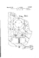
45, My invention willbe vwell understood by reference to the following description'vof the single illustrativeembodiment; thereof show-n, byway of 'ez'cam'ple;intheac'companying drawinga'wherein I l e' Fig; 1 is a sideelevationio'f, thetop vcutterthe vicinity of the cutter head unit; and v Application filed lldv 'einbei" 10, 1930. Serial No. 494,497.;
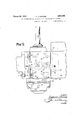
head of a molder shown supported by my improved structure, the main frame of the molder being brokeniaway and shown only in i I Fig; 2isa plan View of. Fig. l.v a
Intheembodiment of myinvention as i1 lustrate'd and which'shows a preferred con; a .struction, 1 designates {a portion of the main frame of a mol'der whichis provided with. a 66 vertical dovetailed slideway'2 forslidably receiving and supporting theyslide,3. '-'The 'I cutter h-eadmotor 4cis mounted for horizontal movement upon the slide. 3, as will be pres ently ;described andndrives the cutter? head axis or spindle 5. Astbest seen in Fig. 2, a
G5 gib ,6 is held betweenthe vertical; dovetailed slid'e way 2rand theslideB by screws-7, and
by examination of this figure it will be clearly apparentthatshould any wearzoccurbetween the gibf6 and the verticaldovetailedhslideway Qorsaidsli'dewa I and the slide 3, by tightena ing the; screws i the gib 6 will be drawn inwardly, thereby ,removingan-y excess play between the slide 3 and thevertical dovetailed slideway 2 a vertical} movement upon the slide'way ,2 and themeans for r'aising andloweringsaid slide upon said slideway consists in elevatingaand lowering screw 8,-rotatably supported in said is received by @the threaded bossv9zoflmain frame 1-, as clearly illustrated in- Fig. l Spiral gear 10is suitablyfixed for rotation with the elevating and lowering screw 8, as by pin 11 and, is in permanent mesh withspiral gear 12, the latter gear beingsuitably f fixed toishaft 13,which is rotatably mounted in bosses 14--14 formed integral with the I slide The outer end ofshait13 is squared to accommodate-a hand crank the crank not being shown. It will, therefore, be seen that when the hand crank is applied to the squared end 13a-of the shaft 13 and rotated; the slide 3 will be moved upwardly upon the the spiral gears 10 and 12 and thescrewS, V respectively, and-when said crank is rotated f i in a reversedirectionsaid slide 3 will be V moved downwardlyupon the verticalidov m I r p As before'st'ated, theslide 'is imountedtor slide13,,the lower threaded end of which v 'r vertical dovetailed slideway 2 by means or i. a .3
The housing 15 of motor i is provided with a horizontal dovetailed projection 16 which fits within the dovetailed horizontal slideway 17, formed within the slide 3. A gib 18 is inserted between the horizontal dovetailed pro'ection 16 and the dovetailed horizontal sli eway 17 and is held therein by means of the screws 19. This gib serves to take up any wear which may occur between the horizontal dovetailed projection 16 of housing'l5 and the dovetailed horizontal slideway 17 of slide 3.
The means for moving the housing 15 of motor 4 horizontall upon the slide 3 consists of shaft 20 wh1ch is rotatably supported within lug 21, said lug being formed integral with the housing 15, the inner threaded end of said screw being received by the threaded hole 22 in slide 3, as clearly shown in Fig. 2. The outer end of shaft 20 is uared to accommodate a hand-crank and w en the hand-crank is attached to said squared end 20a of said shaft and rotated, the threaded end of said shaft, working within the threaded hole 22 in slide 3, moves the lug 21 and, consequently, the motor housing 15 and motor 4 inwardly and when said crank is rotated in a reverse direction, said lug 21 will be moved outwardly, thus moving the housin 1 15 and motor 4 outwardly. Thus it will e seen that by rotating the threaded shaft 20 the motor housing 15 can be moved horizontally upon the slide 3.
' The parts mentioned thus far are wellknown to those skilled in the art of woodworking machinery and constitute what is known as an overhung cutter head unit. With a construction of this nature the motor housing 15 is supported only by the slide 3 and the slide supported only upon the frame 1 and due to the weight of said housin motor 4 and other parts of the cutter hea unit, the slide has a tendency to sag outwardly and downwardly away from the main frame 1 in an approximate direction of arrow A, thus'allowing considerable vibration of the cutter head unit in the event that the rotor of the motor 4 is sli htly out of balance, or if* the cutter head not shown) be out of balance. I
In order to overcome these objections and to further strengthen and support the housing 15, I provide a supporting member or extension 23, suitably fixed to and above the main frame 1 and provided with an adjustable tapered gib 24 which is adapted to tightly fit against a vertically disposed wall 25 formed integral with the motor housing 15. The adjustment of the gib 24:, as shown in Fig. 2, is accomplished through the screw 26 which is passed through a hole in said supporting member 23 and threaded within boss 27, said boss being formed integral with said gib, as best seen in Fig. 2. By means of this gib 2t and supporting member 23, one side of the motor housing 15 is rigidl supported, and by means of the slide 3, t e opposite side of the, motor housing is supported, thereby eliminating the overhung construction and reducing vibration of the cutter 7 head unit to a minimum. By use of the be 18 and 24, the motor housing 15 is rigidly supported'between the slide 3 and thesupportingmember 23 and by use of the gibs gib 24 P head units are rigidly supported at all times I and are capable of being. adjusted, both vertically and horizontally which eliminates, to a minimum, vibration of said cutter head units and produces a machine capable of performing perfect work. I
,While I have shown and described one particular embodiment of my invention, it is to be understood that certain changes and modifications can be made without departing from the scope or spirit thereof, the invention being limited only by the appended claims. What I claim as new and desire to secure byLettersPatent is: i
1. In a molder or like woodworking machine, the means for supporting the upper or top cutter head unit which comprises a bed or main frame, a. cutter head unit having its axis above the bed of said machine, an extension above the bed and to one side of said cutter, a slide mounted for vertical movement on said extension and adapted to carry one side of-said cutter head unit, means permitting horizontal movement ofsaid cutter relative to said slide, and a similar parallel extension located a above the bed of the machine and on the other sideofsaid cutter head unit to hold the latter and guide it against the slideand the slide in turn against the first-named extension.
2. In a woodworking machine, suchas a molder, the means for supporting the upper cutter comprising the combination of a bed, an extension extending above said bed and to one side of said cutter, a slide mounted for vertical movement upon said extension, a cutterhead unit carried by said slide and having its axis above said bed, means for mov-.
ing said cutter in a horizontal direction upon said slide and relative to said bed, anda second extension located above said bed and 7 3. A support for top cuttervhead units of molders and like" Woodworking machines compr sing, 111 combination w th the main 7 frame or bed of such machines,v a vertical dovetailed slidevvay extending above said bed,'a slide mounted for vertical movement thereon, means for moving said slide, a cuta ter head unit mounted for horizontal move' ment on said slide including a motor housing, 1 a vertically'disposed Wall on said housing parallel With said vertical dovetailed slides v Wayand an extension or supporting member located above said bed and having one face parallel with said slideway and in engagement with said Wall of said; motor housing to hold and guide said cutter head unit and.
said slideway, substantially as slide against described.
4:. In a molder or like Woodworking ma-: chine, the support for the top. cutter head 'unit' which comprises the combination ofa main frame or bed, a verticalslideway eX-i tending above said bed, a slide mounted for vertical movement thereon, a cutter head unit mounted for horizontal movement on said slide, a vertically disposed Wall on said cutter head unit parallel with said slideway and an extensionor supporting member located above said bed and having one face in engagement with said vertically disposed .Wall of said cutter head unit to hold and 7 guide said unit and slide against said slide- Way, substantially as-described.
FREDERICK J. KISTNER.
Priority Applications (1)
| Application Number | Priority Date | Filing Date | Title |
|---|---|---|---|
| US494497A US1851256A (en) | 1930-11-10 | 1930-11-10 | Support for top and bottom cutter head motors of molders |
Applications Claiming Priority (1)
| Application Number | Priority Date | Filing Date | Title |
|---|---|---|---|
| US494497A US1851256A (en) | 1930-11-10 | 1930-11-10 | Support for top and bottom cutter head motors of molders |
Publications (1)
| Publication Number | Publication Date |
|---|---|
| US1851256A true US1851256A (en) | 1932-03-29 |
Family
ID=23964723
Family Applications (1)
| Application Number | Title | Priority Date | Filing Date |
|---|---|---|---|
| US494497A Expired - Lifetime US1851256A (en) | 1930-11-10 | 1930-11-10 | Support for top and bottom cutter head motors of molders |
Country Status (1)
| Country | Link |
|---|---|
| US (1) | US1851256A (en) |
Cited By (1)
| Publication number | Priority date | Publication date | Assignee | Title |
|---|---|---|---|---|
| US2461443A (en) * | 1944-10-06 | 1949-02-08 | Missourl Meerschaum Company | Pipe bowl turning machine |
-
1930
- 1930-11-10 US US494497A patent/US1851256A/en not_active Expired - Lifetime
Cited By (1)
| Publication number | Priority date | Publication date | Assignee | Title |
|---|---|---|---|---|
| US2461443A (en) * | 1944-10-06 | 1949-02-08 | Missourl Meerschaum Company | Pipe bowl turning machine |
Similar Documents
| Publication | Publication Date | Title |
|---|---|---|
| US2850054A (en) | Tilting arbor saw | |
| US2823591A (en) | Tool adjustment | |
| US1851256A (en) | Support for top and bottom cutter head motors of molders | |
| US1651013A (en) | Motor-driven planer | |
| US1908478A (en) | Machine tool | |
| US765447A (en) | Milling-machine. | |
| US2512419A (en) | Saw table with vertically adjustable circular saw | |
| US1420323A (en) | Machine tool | |
| US2709463A (en) | Insert-slotting attachment for gang rip saw | |
| US1127969A (en) | Apparatus for holding motors. | |
| US2148369A (en) | Cut-off machine | |
| CN108943185A (en) | A kind of timber trimming equipment | |
| US1362816A (en) | Radial milling-machine | |
| US1556832A (en) | Pull-rod pump jack | |
| CN208713618U (en) | A kind of spiral case making positioning mechanism | |
| US1777497A (en) | Reproducing apparatus | |
| US1598202A (en) | Profiling machine | |
| RU2680487C2 (en) | Machine tool with onboard motor | |
| US989284A (en) | Woodworking machinery. | |
| US2359295A (en) | Milling machine | |
| CN223210861U (en) | Vertical machining center | |
| US653494A (en) | Sculpture-copying machine. | |
| US972297A (en) | Universal lathe. | |
| US1853026A (en) | Torch cutting machine | |
| US227223A (en) | george w |