US1851233A - Screen construction for automobiles - Google Patents
Screen construction for automobiles Download PDFInfo
- Publication number
- US1851233A US1851233A US390172A US39017229A US1851233A US 1851233 A US1851233 A US 1851233A US 390172 A US390172 A US 390172A US 39017229 A US39017229 A US 39017229A US 1851233 A US1851233 A US 1851233A
- Authority
- US
- United States
- Prior art keywords
- screen
- section
- channel
- roller
- housing
- Prior art date
- Legal status (The legal status is an assumption and is not a legal conclusion. Google has not performed a legal analysis and makes no representation as to the accuracy of the status listed.)
- Expired - Lifetime
Links
- 238000010276 construction Methods 0.000 title description 6
- 238000000465 moulding Methods 0.000 description 4
- 239000011521 glass Substances 0.000 description 2
- 230000000712 assembly Effects 0.000 description 1
- 238000000429 assembly Methods 0.000 description 1
- 238000004519 manufacturing process Methods 0.000 description 1
- 239000000463 material Substances 0.000 description 1
- 239000002184 metal Substances 0.000 description 1
- 238000009966 trimming Methods 0.000 description 1
Images
Classifications
-
- B—PERFORMING OPERATIONS; TRANSPORTING
- B60—VEHICLES IN GENERAL
- B60J—WINDOWS, WINDSCREENS, NON-FIXED ROOFS, DOORS, OR SIMILAR DEVICES FOR VEHICLES; REMOVABLE EXTERNAL PROTECTIVE COVERINGS SPECIALLY ADAPTED FOR VEHICLES
- B60J1/00—Windows; Windscreens; Accessories therefor
- B60J1/20—Accessories, e.g. wind deflectors, blinds
- B60J1/2011—Blinds; curtains or screens reducing heat or light intensity
- B60J1/2013—Roller blinds
-
- Y—GENERAL TAGGING OF NEW TECHNOLOGICAL DEVELOPMENTS; GENERAL TAGGING OF CROSS-SECTIONAL TECHNOLOGIES SPANNING OVER SEVERAL SECTIONS OF THE IPC; TECHNICAL SUBJECTS COVERED BY FORMER USPC CROSS-REFERENCE ART COLLECTIONS [XRACs] AND DIGESTS
- Y10—TECHNICAL SUBJECTS COVERED BY FORMER USPC
- Y10S—TECHNICAL SUBJECTS COVERED BY FORMER USPC CROSS-REFERENCE ART COLLECTIONS [XRACs] AND DIGESTS
- Y10S160/00—Flexible or portable closure, partition, or panel
- Y10S160/02—Auto screens and miscellaneous
Definitions
- thetube 8 has, a longitudinal-
- This invention relates generally to screen assemblies, particularly to those designed for use in connection with the windows of yehicle bodies, and consists of certain novel features of construction, combinations and arrangements of parts that will be hereinaftermore fully described, and particularly pointed out in the appended claims.
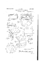
- FIG. 1 is a fragmentary side elevation of a vehicle body with a screen assembly embodying my invention applied thereto;
- Figure 2 is a detail elevation of the screen assembly per se; i
- Figure 3 is an end elevation of the housmg;
- Figure 4 is a perspective view of one section of the housing;
- Figure 5 is a perspective view of the other section of the housing
- Figure 6 is a bottom plan view of the hous- Figure 7 is a fragmentary sectionalview through one endof the housing;
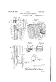
- Figure 8 is asectional view taken on the line 8-8 of Figure 3;
- Figure 9 is a fragmentary sectional View of the vehicle body and screen assembly
- Figure 10 is a cross sectional View through the roller and showing a portion of the screen applied thereto;
- Figure 11 is a fragmentary elevation of one of the roller headers
- Figure 12 is a longitudinal sectional vlew taken on the line 1212 of Figure 11.
- Figure 13 is a vertical sectinal view through a portion of a window with my screen assembly applied thereto.
- Figure 14 is a vertical sectional View through the window, channel strip and header and showingthe screen assembly in elevation.
- 1 is a screen of flexible material
- 2 is a roller upon which the screen 1 is adapted to be wound
- the housing 3 is also formed of sheet metal and comprises twosections, 12 and 13.
- the section 12 is substantially L-shape in crosssection and has vthe end pieces. 14:, while the other section 13 is channel shaped and is also provided at its opposite ends withIintegral webs 15.
- the end pieces 1% carry the roller and the section 13 is narrower thanthetopwall 18 and terminates short of the upright wall 22 vofthe section 12, thereby providing an opening or slot 23 for the screen 1.
- wall 21. is provided at its free edge with an open return-bent flange 24 that stifiens and reinforces the construction and that also constitutes a bearing for the screen as it passes through the opening 23 to and from the roller.
- each guide comprises a screen receiving channel 30, and a laterally extending finish strip 31.
- the channel 30 is relatively narrow and is provided at its free edges with close return-bent portions 32 and 33, while the finish strip 31 projects laterally from the return-bent portion 33zat a point substantially midway between the base 34 andfree edges of the channel and is I provided with an open return-bent portion
- The'molding Goonstitutes a window sill and comprises an inverted channel member having an inturned marginal flange 6.
- the housing 3, molding 6, and guides 4 and 5 form a frame that as a unit may be mounted wherever desired.
- it is used opposite a window opening 40 in a door 41 of a vehicle body, and has been substituted for the usual molding heretofore used upon the inner side of the door as trimming around the edges of the window opening.
- the housing 3 is at the upper edge of the opening 40; the guides 4 and 5 are at the sides of the opening 40; and the molding 6 is at the lower edge of the opening.
- the outside panel 45 of the door overlies the upright frame members 46 and has the usual inturned flanges 47 at the edges of the opening 40.
- the channel runways 48 for the sliding glass panel 49 are secured in rabbets 50 of the inturned flanges 47.
- the screen channels 30 are against the glass runway channels 48, and the flanges 35 are secured to the inner sides of the upright frame members 46.
- a channel strip is secured upon the upper edge of the sliding window 49 and is provided with a downwardly and outwardly inclined flange 61 that is engageable with a lateral flange 62 of a tab 63 at the free end of the screen 1 for moving the screen downwardly with the window 49 as the latter is lowered by its regulator mechanism (not shown).
- the inner walls 64 of the screen channels 30 are offset inwardly, as illustrated at 65, to permit the tab 63 to be pulled laterally inwardly so that the flange 62 of the tab may be disengaged from the lateral flange 61 of the strip 60 on the window.
- the screen 1 will then be free to move upwardly in thechannels 30 and be wound upon the roller.
- the screen may be moved automatically to operative posit: on as the window 49 is opened.
- it may be easily and quickly released and raised whenever desired, for instance when the driver wishes to extend his arm through the window opening 40 to give the traffic signal.
- a housing comprising two sections secured together, one section being substantially L-shape in cross section and having end pieces, and the other section being substantially channel shaped andhaving a wall thereof overlapping and secured to a wall of the first section and having another wall in spaced relation to a wall of the first section and providing a screen opening.
- a housing for a screen roller comprising two sections, one being substantially L-shape in cross section and having end pieces, provided with means for carrying a roller, the other section being substantially channel-shape and provided at its opposite ends with inturned webs, one side wall of the channel section overlying one wall of the L section, and the end pieces overlapping the webs.
- a housing for a screen roller comprising two sections, one being substantially L-shape in cross section and having end pieces provided with means for carrying a roller, the other section being substantially channel-shape and provided at its opposite ends with inturned webs, one side Wall of the channel section overlying one wall of the L section, and the end pieces overlapping the webs, the other side wall of the channel section terminating short of the upright wall of the L section and providing a slot for a screen.
- a housing for a screen roller comprising two sections, one being substantially L-shape in cross section and having end pieces, and the other section being substantially channelshape, one side Wall of the channel overlapping and being secured to one side wall of the L section, the other side wall of the channel extending toward but terminating short of the other side Wall of the L section, and the base of the channel having portions at opposite ends secured to the end pieces of the L section.
Landscapes
- Engineering & Computer Science (AREA)
- Mechanical Engineering (AREA)
- Operating, Guiding And Securing Of Roll- Type Closing Members (AREA)
Description
MEWCEE 2%, 1932. A. L 1,853,233
SCREEN CONSTRUCTION FOR AUTOMOBILES Filed Sept. 3, 1929 2 Sheets-Sheet 1 INVENTOR 2% +3 fldarz-fBaZZ arch 29, 1932. p;
SCREEN CONSTRUCTION FOR AUTOMOBILES BALL Filed Sept. 3. 1929 2 Sheets-Sheet 2 INVENTOR fldfizrz F254; 22
ATTORNEY Patented Mai-. 29, 1932 UNITED srA TE P ENT, orn ca v ALBERT ILBAIJL, OFDE'IROIT, MICHIGAN, ASSIGNOR TO BRIGGS MANUFACTURING COM- f PANSLOFQDETEOIT, IvTICHIGAN, A COMPANY MICHIGAN SCREEN CONSTRUGTIGN FOR AUTOMGBILES Application filed september 3, 1929; Serial No. 3e0,172.- I
9,, Preferably thetube 8 has, a longitudinal- This invention relates generally to screen assemblies, particularly to those designed for use in connection with the windows of yehicle bodies, and consists of certain novel features of construction, combinations and arrangements of parts that will be hereinaftermore fully described, and particularly pointed out in the appended claims.
In the accompanying drawings:
Figure 1 is a fragmentary side elevation of a vehicle body with a screen assembly embodying my invention applied thereto;
Figure 2 is a detail elevation of the screen assembly per se; i
Figure 3 is an end elevation of the housmg; Figure 4 is a perspective view of one section of the housing;
Figure 5 is a perspective view of the other section of the housing;
Figure 6 is a bottom plan view of the hous- Figure 7 is a fragmentary sectionalview through one endof the housing;
. Figure 8 is asectional view taken on the line 8-8 of Figure 3;
Figure 9 is a fragmentary sectional View of the vehicle body and screen assembly;
Figure 10 is a cross sectional View through the roller and showing a portion of the screen applied thereto;
Figure 11 is a fragmentary elevation of one of the roller headers;
Figure 12 is a longitudinal sectional vlew taken on the line 1212 of Figure 11.
Figure 13 is a vertical sectinal view through a portion of a window with my screen assembly applied thereto.
Figure 14 is a vertical sectional View through the window, channel strip and header and showingthe screen assembly in elevation.
Referring now to the drawings, 1 is a screen of flexible material, 2 is a roller upon which the screen 1 is adapted to be wound, .3
isa housing for the roller, 4 and 5 respectively ably comprises a tube 8 and a pair of headers ly ext-ending seam l0 and has a longitudinally extending groove 11 in which one end or edge of the screen lis anchored, while the headers 9'are secured within the tube 8 at opposite ends thereof and in action simulate the'usual window curtain headers for supporting and actuating the roller in the housing.
In the present instance the housing 3 is also formed of sheet metal and comprises twosections, 12 and 13. As shown, the section 12 is substantially L-shape in crosssection and has vthe end pieces. 14:, while the other section 13 is channel shaped and is also provided at its opposite ends withIintegral webs 15. The end pieces 1% carry the roller and the section 13 is narrower thanthetopwall 18 and terminates short of the upright wall 22 vofthe section 12, thereby providing an opening or slot 23 for the screen 1. Preferably this. wall 21. is provided at its free edge with an open return-bent flange 24 that stifiens and reinforces the construction and that also constitutes a bearing for the screen as it passes through the opening 23 to and from the roller.
The guides 4 and 5 are similar in construc- 1 tion and extend between the housing 3 and moldingfi. Preferably each guide comprises a screen receiving channel 30, and a laterally extending finish strip 31. The channel 30 is relatively narrow and is provided at its free edges with close return-bent portions 32 and 33, while the finish strip 31 projects laterally from the return-bent portion 33zat a point substantially midway between the base 34 andfree edges of the channel and is I provided with an open return-bent portion The'molding Goonstitutes a window sill and comprises an inverted channel member having an inturned marginal flange 6.
As shown, the housing 3, molding 6, and guides 4 and 5 form a frame that as a unit may be mounted wherever desired. In the present instance it is used opposite a window opening 40 in a door 41 of a vehicle body, and has been substituted for the usual molding heretofore used upon the inner side of the door as trimming around the edges of the window opening. Preferably the housing 3 is at the upper edge of the opening 40; the guides 4 and 5 are at the sides of the opening 40; and the molding 6 is at the lower edge of the opening.
As shown, the outside panel 45 of the door overlies the upright frame members 46 and has the usual inturned flanges 47 at the edges of the opening 40. The channel runways 48 for the sliding glass panel 49 are secured in rabbets 50 of the inturned flanges 47. The screen channels 30 are against the glass runway channels 48, and the flanges 35 are secured to the inner sides of the upright frame members 46.
WVith the present construction, a channel strip is secured upon the upper edge of the sliding window 49 and is provided with a downwardly and outwardly inclined flange 61 that is engageable with a lateral flange 62 of a tab 63 at the free end of the screen 1 for moving the screen downwardly with the window 49 as the latter is lowered by its regulator mechanism (not shown). Preferably the inner walls 64 of the screen channels 30 are offset inwardly, as illustrated at 65, to permit the tab 63 to be pulled laterally inwardly so that the flange 62 of the tab may be disengaged from the lateral flange 61 of the strip 60 on the window. The screen 1 will then be free to move upwardly in thechannels 30 and be wound upon the roller. Thus the screen may be moved automatically to operative posit: on as the window 49 is opened. Moreover, it may be easily and quickly released and raised whenever desired, for instance when the driver wishes to extend his arm through the window opening 40 to give the traffic signal.
While it is believed that from the foregoing description the nature and advantages of the invention will be readily apparent, I desire to have it understood that I do not limit myself to what is herein shown and described and that such changes may be resorted to when desired as fall Within the scope of what is claimed.
What I claim as my invention is:
1.In a screen assembly, a housing comprising two sections secured together, one section being substantially L-shape in cross section and having end pieces, and the other section being substantially channel shaped andhaving a wall thereof overlapping and secured to a wall of the first section and having another wall in spaced relation to a wall of the first section and providing a screen opening.
2. In an assembly of the class described, a housing for a screen roller comprising two sections, one being substantially L-shape in cross section and having end pieces, provided with means for carrying a roller, the other section being substantially channel-shape and provided at its opposite ends with inturned webs, one side wall of the channel section overlying one wall of the L section, and the end pieces overlapping the webs.
3. In an assembly of the class described, a housing for a screen roller comprising two sections, one being substantially L-shape in cross section and having end pieces provided with means for carrying a roller, the other section being substantially channel-shape and provided at its opposite ends with inturned webs, one side Wall of the channel section overlying one wall of the L section, and the end pieces overlapping the webs, the other side wall of the channel section terminating short of the upright wall of the L section and providing a slot for a screen.
4. In an assembly of the class described, a housing for a screen roller, comprising two sections, one being substantially L-shape in cross section and having end pieces, and the other section being substantially channelshape, one side Wall of the channel overlapping and being secured to one side wall of the L section, the other side wall of the channel extending toward but terminating short of the other side Wall of the L section, and the base of the channel having portions at opposite ends secured to the end pieces of the L section.
In testimony whereof I affix my signature.
ALBERT P. BALL.
Priority Applications (1)
| Application Number | Priority Date | Filing Date | Title |
|---|---|---|---|
| US390172A US1851233A (en) | 1929-09-03 | 1929-09-03 | Screen construction for automobiles |
Applications Claiming Priority (1)
| Application Number | Priority Date | Filing Date | Title |
|---|---|---|---|
| US390172A US1851233A (en) | 1929-09-03 | 1929-09-03 | Screen construction for automobiles |
Publications (1)
| Publication Number | Publication Date |
|---|---|
| US1851233A true US1851233A (en) | 1932-03-29 |
Family
ID=23541387
Family Applications (1)
| Application Number | Title | Priority Date | Filing Date |
|---|---|---|---|
| US390172A Expired - Lifetime US1851233A (en) | 1929-09-03 | 1929-09-03 | Screen construction for automobiles |
Country Status (1)
| Country | Link |
|---|---|
| US (1) | US1851233A (en) |
-
1929
- 1929-09-03 US US390172A patent/US1851233A/en not_active Expired - Lifetime
Similar Documents
| Publication | Publication Date | Title |
|---|---|---|
| US1721223A (en) | Signal window | |
| US2900207A (en) | Road vehicle door construction | |
| US1851233A (en) | Screen construction for automobiles | |
| US1388091A (en) | Automobile-window attachment | |
| US1823290A (en) | Window screen for closed automobiles | |
| US2565232A (en) | Window guide | |
| US2034528A (en) | Ventilating device | |
| US1876589A (en) | Door construction | |
| US2093860A (en) | Vehicle window | |
| US2283002A (en) | Channel assembly | |
| US2165594A (en) | Automobile body construction | |
| US1938007A (en) | Car body for closed passenger automobiles | |
| US1986200A (en) | Window screen | |
| US1620166A (en) | Vehicle signaling window | |
| US1678262A (en) | Roof for closed vehicle bodies | |
| US1671433A (en) | Closed automobile body | |
| US1866983A (en) | Automobile window screen | |
| US1924705A (en) | Draft shield | |
| US1987297A (en) | Vehicle body | |
| US1627760A (en) | Windshield screen | |
| US1835174A (en) | Vehicle window | |
| US1940625A (en) | Window and curtain guide construction | |
| US2033874A (en) | Ventilating window mechanism | |
| US2058087A (en) | Ventilating and signal window construction | |
| US1326676A (en) | Window |