US1851228A - Slip-switch timing mechanism - Google Patents
Slip-switch timing mechanism Download PDFInfo
- Publication number
- US1851228A US1851228A US556895A US55689531A US1851228A US 1851228 A US1851228 A US 1851228A US 556895 A US556895 A US 556895A US 55689531 A US55689531 A US 55689531A US 1851228 A US1851228 A US 1851228A
- Authority
- US
- United States
- Prior art keywords
- shaft
- members
- circuit
- blocks
- switch
- Prior art date
- Legal status (The legal status is an assumption and is not a legal conclusion. Google has not performed a legal analysis and makes no representation as to the accuracy of the status listed.)
- Expired - Lifetime
Links
- 239000000969 carrier Substances 0.000 description 35
- 239000002184 metal Substances 0.000 description 10
- 229910052751 metal Inorganic materials 0.000 description 10
- 239000004020 conductor Substances 0.000 description 6
- 229910002804 graphite Inorganic materials 0.000 description 6
- 239000010439 graphite Substances 0.000 description 6
- 239000011435 rock Substances 0.000 description 6
- OKTJSMMVPCPJKN-UHFFFAOYSA-N Carbon Chemical compound [C] OKTJSMMVPCPJKN-UHFFFAOYSA-N 0.000 description 2
- XEEYBQQBJWHFJM-UHFFFAOYSA-N Iron Chemical compound [Fe] XEEYBQQBJWHFJM-UHFFFAOYSA-N 0.000 description 2
- 239000011810 insulating material Substances 0.000 description 2
- 229910052799 carbon Inorganic materials 0.000 description 1
- 229910052742 iron Inorganic materials 0.000 description 1
- 238000003825 pressing Methods 0.000 description 1
Images

Classifications
-
- H—ELECTRICITY
- H01—ELECTRIC ELEMENTS
- H01H—ELECTRIC SWITCHES; RELAYS; SELECTORS; EMERGENCY PROTECTIVE DEVICES
- H01H43/00—Time or time-programme switches providing a choice of time-intervals for executing one or more switching actions and automatically terminating their operations after the programme is completed
- H01H43/10—Time or time-programme switches providing a choice of time-intervals for executing one or more switching actions and automatically terminating their operations after the programme is completed with timing of actuation of contacts due to a part rotating at substantially constant speed
- H01H43/12—Time or time-programme switches providing a choice of time-intervals for executing one or more switching actions and automatically terminating their operations after the programme is completed with timing of actuation of contacts due to a part rotating at substantially constant speed stopping automatically after a single cycle of operation
- H01H43/125—Time or time-programme switches providing a choice of time-intervals for executing one or more switching actions and automatically terminating their operations after the programme is completed with timing of actuation of contacts due to a part rotating at substantially constant speed stopping automatically after a single cycle of operation using a cam
- H01H43/127—Time or time-programme switches providing a choice of time-intervals for executing one or more switching actions and automatically terminating their operations after the programme is completed with timing of actuation of contacts due to a part rotating at substantially constant speed stopping automatically after a single cycle of operation using a cam with provision for adjustment of the intervals by means carried by the cam
Definitions
- This invention relates to mechanism for controlling electric circuits by opening or closing the same in predetermined times and predetermined order after the performance of P an initial operation which starts the mechanism into operation, and for resetting the circuit-controlling members in their initial positions so that the operations may be repeated.
- the mechanism comprises a shaft which is rotated at a very slow and constant speed; a series of switch members mounted upon a stationary support ad- .20 jacent the shaft, a plurality of cricuit-controlling members loosely journaled on the shaft and adapted to engage the stationary members, the circuit-controlling members being biased away from the stationary members and adapted to rock freely on the shaft into engagement with a fixed stop; friction devices of conducting material rotatable with the shaft and arranged on opposite sides of the circuit-controlling members, and means for clamping said devices against the circuitcontrolling members to cause the latter to move with the shaft in the direction to engage the stationary members.
- Each circuit-controlling member has an arm which is adjustable toward and from the opposing stationary member, to vary the time of engagement of the arm with the latter member.
- the shaft rotates very slowly and at aknown speed, so that by adjusting the arm on the circuit-controlling member the time of engagement may be accurately pro-set.
- the former member stops, while the friction deviceswhich engage it continue in operation, holding the former member in engagement with the latter.
- the friction devices are released from the circuit-controlling members and the latter then rock on the shaft to their initial positions against a fixed stop.
- the present invention relates more particularly to the moun ing of the friction devices and the circuit-controlling members, whereby the engagement and disen agement ofthe friction devices with the circuit-controlling members is improved.
- F a is a section on the line 4- l of Fig. 2;
- F 5 is a similar section showing the apparatus as used to open circuits
- FIG. 6 is a perspective view of one ofthe friction-block carriers
- Fig. 7 is a side elevation of one of the movable switch members, its contact arm being removed;
- Fig. 8 is a side elevation of a modified form of friction-block carrier, and,
- Fig. 9 is an edge view of the same, looking from right to left in Fig. 7.
- 1 indicates a suitable base of insulating m terial to which are secured forwardly projecting metal bars 2 and 3, spaced apart from one another and forming supports for the working parts of the apparatus.
- a tubular t extends horizontally through these of the apparatus shaft bars and is journaled therein, and upon this shaft is mounted a worm wheel 5, which is geared to a smallelectric motor 6 by reduction gearing whicn causes the worm wheel and shaft l to turn at a very low speed when the motor is in operation.
- the motor is one which operates at constant speed.
- a number of disks a, 01-, a and a which constitute carriers for blocks of electrically conductive material '7, preferably carbongraphite composition, are mounted upon the shaft so as to turn with it.
- the carrier a is fir dly secured to the shaft by a set screw 8.
- This carrier has two diametrically opposite sockets 8 in which are fittedthe two cylindrical blocks 7 of carbon-graphite composition.
- the carriers a, a and a are alike, each comprising a disk 9 having two diametrically opposite cylindrical sleeves 9 which extend parallel with the axis of the disk and consti tute holders for the cylindrical carbongraphite blocks 7. These blocks fit closely within the holders, but are freely movable longitudinally therein and project beyond their ends.
- Each of these carriers has a hub 9 which fits on to the shaft 4, and a tongue 9 on the hub extends into a keyway 10 in the shaft, so that the carrier may be driven by the shaft.
- the hub projects atone side of the disk for a considerable distance beyond the ends of the holders on that side, this part 9 of the-hub forming a bearing for a circuitcontrolling member hereinafter described.
- the carriers a, a ,'a are assembled on the hollow shaft 4 by sliding their hubs over the left hand end of the shaft successively and then applying the nut 46 to said shaft which clamps the hubs together andagainst the hub of the carrier a.
- circuit-com trolling members Z), Z), and 5 each member comprising a metal plate 11 having a central opening 12 through which a hub of one of the carriers is extended.
- the circuit-controlling members fit closely around the hubs but are freely rotatable thereon.
- the plates are in the form of disks which, for about onehalf of their circumferential lengths, project radially beyond the peripheries of the carriers, and the projecting portion of each plate has a flange 13 which projects at opposite sides of the plate. This flange, on each plate, forms a support and guide for an adjustable arm.
- a U-shaped clamp or yoke 14 fits around the flange of the member I) and an arm 15 has a short right-angled portion m, which is clamped against the periphery of the flange by a set screw 16 at the center of the clamp or yoke.
- Similar arms 15 and 15 are adjustably secured to the flanges of the members 7) and b by clamps 14*, 149, respectively, and these arms 15 and 15 are adapted to engagb stationary switch members 0 and respectively.
- a weight 17 projects radially from the member I) at one end of its flange, and similarly arranged weights 17 and 17 project from the members I) and I). These weights tend to rock the plates to which they 'areattached so as to hold the arms out of engagement with the stationaryswitch members, and normally a strip of insulating material 18 which is bracket 19 connected to the these weights rest against 1 disk 21 to bear against the blocks in the car- 7 rier a and the blocks in the several carriers, which are movable endwise in the sleeves or holders, will be clamped against the circuitcontrolling members 5, b and IF.
- a magnet (Z is suspended beneath the supporting bars 2 and 3 by an iron plate 22, which is secured to said bars, and has a downwardly turned part 22 in which an armature 23 is pivotally mounted.v
- This armature has an arm 24' which projects upwardly and has an opening through which the right hand end portion of the shaft extends.
- the shaft 20 has a shoulder 20?) and when the magnet is de-energized and its armature is away from its pole-piece, 7 against the shoulder and holds the rod in position to release the friction-blocks, as shown in Figs. 1 and 3. normally held in this position by a spring 25 which is coiled upon a stud 26, the latter projecting horizontally from the arm 22 on the support 22 through an opening in the arm 24.
- the arm 24 constitutes a lever for moving the shaft 20.
- a projection 27 is provided and this forms a ful-V cruin for another lever 28, the lower end of whicn is interposed between the spring 25 and the lever 2d.
- the upper end of the levr 28 has an opening through which the shaft2Q extends and this end of the lever bears against a washer 29 which is held in place by a cotter pin 30, passing through the shaft 20.
- a conductor 31- is shown connected to the supporting bar 3 and all of the movable parts of the apparatus are electrically connected to this support and wire 31.
- Conductors 33 and 34- are shown connected to the switch
- the armature is the arm 2s presses the washer ios members 0, 0, and '0 respectively.
- the coil of the magnet may be connected to the current source in any desired way, according to the use which is to be made of the apparatus.
- the shaft at turns in the clockwise direction when viewed from its right hand end, while the weights on the circuit-controlling members tend to rock said members on the shaft away from the stationary switch members. Normally, the circuit-controlling members are held out of engagement with the station ary switch members by the weights on the former, which rests against the stop 18.
- the motor may run constantly, or it may be switched into and out of circuit, as desired, according to the purpose for which the apparatus used.
- the arms on the circuit-controlling members will be set at any desired distance from the stationary switch members according to the delay desired in closing the circuits. Assuming the motor to be running and the arms to be set as shown in Figs.
- the number of friction devices and switch members mounted on the shaft may be varied, as also the speed of the shaft. For some special purposes the gearing will be such that the shaft will turn very slowly, say onehalf revolution in ten minutes.
- the arms on the circuit-controlling members may be se. to close the switches at exact times, as for instance, ten seconds for one switch, five minutes for another and two minutes for another, and as soon as the friction devices are unclamped from the circuit-controlling members, the latter immediately return to their initial positions so that the operation may be repeated.
- the carriers are not movable upon the shaft, but the friction blocks are movable longitudinally in their holders and the plates of the movable contact members are laterally movable on'the carrier hubs, so that these plates are clamped by pressure transmitted through the blocks and not through the carriers.
- friction-blocks of carbon-graphite composition
- the stationary switch members are shown conventionally as metal posts which the arms on the circuit-controlling members directly engage to close circuits, which circuits are broken when said members are released from the friction devices.
- the mechanism is used to actuate normally closed switches to open circuits, as illustrated in Fig. 5, and for some uses some of the switches may be normally closed and others normally open, or they may be all normally closed, or normally open.
- a stationary normally closed switch 0 comprising a switch lever 42 centrally pivoted on metal post 43 and having one end normally held against a metal post 44 by a spring 45. These posts are terminals of a circuit 46 to be controlled.
- the opposite ends of the lever is shown covered by a piece of insulating material 47 which the arm 15 of the circuit-controller b is adapted to engage when the mechanism is operated, and it will be evident that as the circuit-controller advances vith the shaft the switch member 42 will be rocked by the arm l5 against a stop 46 and the circuit will be opened. When the friction devices are released and the circuit-controller drops back to normal position, the spring 45 will rock the switch arm to its normal closed position.
- the stationary switches may be of the push button type and normally open or normally closed, as desired. lVhen such are used the arms on the circuit-controllers serve merely as tappets to actuate the stationary switches, and not as switch members.
- circuit-controlling members operated from a common shaft. It will be obvious that the number of such members may be increased as desired, according to the number of circuits to be controlled, by providing a longe shaft and additional friction devices.
- the mechanism is used mainly for controlling electric motors where the motor is required to operate a'machi'ne at different speeds, or for different given periods, and to repeat these operations.
- the contactor comprises an angular metal plate 35, having a hub 36, adapted to fit on to the shaft 4.
- studs 37 project in the plane of. the plate and at right angles to said edges, and upon these studs are pivoted short pieces of square tubing 38 which are about as long as the plate and which lie parallel with the aforesaid edges.
- This carrier rotates in the direction to drag the carbon-graphite blocks around, which direction is indicated by the arrow in Fig. 8. It will be evident that as the tubes may swing around the pivots 37 and the blocks may swing to a limited extent around the pivots 41, the blocks can move when the clamping disk is moved to clamp or release the switch members while the plates, which constitute the bodies of'the carriers, will be rigid with the shaft under all conditions.
- An electric slip-switch mechanism comprising a shaft and means for rotating the same, a switch member adjacent the shaft, a circuit-controlling member rotatable about the shaft and also movable longitudinally thereof, carriers secured to the shaft on opposite sides of the latter member, frictionblocks mounted in said carriers, the blocks in one of said carriers being movable toward and from the opposing carrier, and means for applying pressure to said latter blocks to cause the circuit-controlling member to be clamped between the blocks of the opposing carriers.
- An electric slip-switch mechanism com prising a shaft and means for rotatingthe same, a plurality of switch membersadjacent the shaft, a plurality of circuit-controlling members rotatable about andmovable longitudinally of the shaft and biased away from said switch members, friction-block carriers at opposite sides of the several circuit-controlling members, sa1d carrlers fixed to the shaft, friction-blocks mounted in sa1d carriers and movable longitudinally of the shaft, and means for clamping said blocks against said movable members to cause the latter to rotate with the shaft into engagement with said switch members.
- An electric slip-switch mechanism comprising a shaft and means for rotating the same, a plurality of switch members adjacent the shaft, a. plurality of circuit-controlling members, the latter rotatable about and movable longitudinally of the shaft and biased away from said switch members, frictionblock carriers at opposite sides of the several circuit-controlling members, said carriers fixed to the shaft, friction-blocks of elec trically conductive material mounted in said carriers and movable longitudinally of the shaft, and means for clamping said blocks against said circuit-controlling members to cause the latter to rotate with the shaft into engagement with said switch members.
- An electric slip-switch mechanism comprising a shaft and means for-rotating the same,'a plurality of switch members adjacent the shaft, a plurality of circuit-controlling members, the latter rotatable about and movable longitudinally of the shaft and biased away from said switch members, friction-block carriers atopposite sides of the several circuit-controlling members, said carriers fixed to the shaft, friction-blocks of electrically conductive material mounted in the carriers in alinement with one another and movable longitudinally of the shaft, and means for clamping said blocks against said circuit-controlling members to cause the.
- An electric slip-switch mechanism comprising a shaft and means for rotating the same, a plurality of switch members adjacent the shaft, a plurality of circuit-controlling members, each of the latter comprising a disk rotatable about and movable longitudinally of the shaft, friction-block-carriers at opposite sides of the several disks, said carriers fixed to the shaft, aplurality of spaced frictionblocks mounted in each carrier, said blocks being movable longitudinally of the shaft and the corresponding blocks in the several carriers being in alinement, and means for clamping said blocks against-said disks and for unclamping the same.
- An electric slip-switch mechanism comprising a shaft and means for rotating the same, a plurality of switch members adjacent the shaft, a plurality of circuit-controlling members, each of the latter comprising a disk rotatable about and movable longitudinally of the sliafhfriction-block carriers at. oppo-' site sides of the several disks, each carrier comprlsinga plate secured to theshaft, friction-blocks mounted in each carrier at opposite sides ofthe shaft, said blocks being movable longitudinally of the shaft, and means for clamping said blocks against said disks and for unclamping the same.
- An electric slip-switch mechanism comprising a shaft and means for rotating the same, a plurality of switch members adjacent the shaft, a plurality of circuit-controlling members, the latter each comprising a disk rotatable about and movable longitudinally of the shaft, friction-block carriers at opposite sides of the several circuit-controlling members, each carrier comprising a plate secured to the shaft and having diametrically opposite sleeves extending parallel With the shaft, friction-blocks movable longitudinally in said sleeves and projecting beyond the same, and means for clamping said blocks against said disks and for unclamping the same.
- An electric slip-switch mechanism comprising a shaft and means for rotating the same, a plurality of frictionblock carriers each comprising a plate having a hub secured to said shaft, friction-blocks carried by said plates and movable longitudinally of the shaft, a plurality of circuit-controlling members, each member journaled on one of said hubs between two of said plates, and means for clamping said blocks against said members and for unclamping the same.
- a friction-block carrier comprising a flat member having means for securing it centrally to a shaft and having arms pivotally connected to its edges at diametrically opposite points and adapted to swing transversely of the plane of said memher, and friction-blocks mounted in the free ends of said arms and projecting beyond their sides.
- a friction-block carrier comprising a flat member having means for securing it cent-rally to a shaft and having arms pivotally connected to its edges at diametrically opposite points and adapted to swing transversely of the plane of said memher, and friction-blocks pivotally mounted in the free ends of said arms and projecting beyond their sides.
Landscapes
- Mechanisms For Operating Contacts (AREA)
Description
March 1932- G. H. WHITTINGHAM SLIP SWITCH TIMING MECHANISM Filed Aug 13, 1951 2 $heets-Sheet March 29, 1932. G. H. WHITTINGHAM SLIP SWITCH TIMING MECHANISM Filed Aug 15, 1931 2 Sheets-Sheet Patented ll lar. 29, 1932 GEORGE E. WI-IZT'IINGHAM, F BALTIMORE, MARYLAND, ASSIGNOR T0 MONITOR CON- TROLLER COMPANY, 0F BALTIMOEE, MARYLAIWD, A'COR-PORATIOII 0F MARYLAND SLIP-SWITCH TIMING EIECHANISM Application filed August 13, 1931. Serial No. 556,895.
This invention relates to mechanism for controlling electric circuits by opening or closing the same in predetermined times and predetermined order after the performance of P an initial operation which starts the mechanism into operation, and for resetting the circuit-controlling members in their initial positions so that the operations may be repeated.
This application is a continuation in part 510 of my application filed July 7, 1930, Serial Number 466,308, and embodies structural im provements upon the invention described in my reissue application Serial Number 550,- 806, filed July 14, 1931.
In the aforesaid reissue application and in the present application, the mechanism comprises a shaft which is rotated at a very slow and constant speed; a series of switch members mounted upon a stationary support ad- .20 jacent the shaft, a plurality of cricuit-controlling members loosely journaled on the shaft and adapted to engage the stationary members, the circuit-controlling members being biased away from the stationary members and adapted to rock freely on the shaft into engagement with a fixed stop; friction devices of conducting material rotatable with the shaft and arranged on opposite sides of the circuit-controlling members, and means for clamping said devices against the circuitcontrolling members to cause the latter to move with the shaft in the direction to engage the stationary members. Each circuit-controlling member has an arm which is adjustable toward and from the opposing stationary member, to vary the time of engagement of the arm with the latter member. The shaft rotates very slowly and at aknown speed, so that by adjusting the arm on the circuit-controlling member the time of engagement may be accurately pro-set. As each circuit-controlling member cngages a stationary member the former member stops, while the friction deviceswhich engage it continue in operation, holding the former member in engagement with the latter. When it is desired to reset the switches, the friction devices are released from the circuit-controlling members and the latter then rock on the shaft to their initial positions against a fixed stop.
The present invention relates more particularly to the moun ing of the friction devices and the circuit-controlling members, whereby the engagement and disen agement ofthe friction devices with the circuit-controlling members is improved.
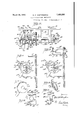
In the accompanying drawings, *ig. 1 is a front elevation of the mecha- 1 1g. 2 is a front elevation of the apparatus, the shaft which operates the circuit-controlling mechanism being shown in longitudinal section;
3 is a top plan view with the motor removed;
F a is a section on the line 4- l of Fig. 2;
F 5 is a similar section showing the apparatus as used to open circuits;
6 is a perspective view of one ofthe friction-block carriers;
Fig. 7 is a side elevation of one of the movable switch members, its contact arm being removed;
Fig. 8 is a side elevation of a modified form of friction-block carrier, and,
Fig. 9 is an edge view of the same, looking from right to left in Fig. 7.
Referring to Figures 1 to 6 of the drawins, 1 indicates a suitable base of insulating m terial to which are secured forwardly projecting metal bars 2 and 3, spaced apart from one another and forming supports for the working parts of the apparatus. A tubular t extends horizontally through these of the apparatus shaft bars and is journaled therein, and upon this shaft is mounted a worm wheel 5, which is geared to a smallelectric motor 6 by reduction gearing whicn causes the worm wheel and shaft l to turn at a very low speed when the motor is in operation. The motor is one which operates at constant speed.
A number of disks a, 01-, a and a which constitute carriers for blocks of electrically conductive material '7, preferably carbongraphite composition, are mounted upon the shaft so as to turn with it. The carrier a is fir dly secured to the shaft by a set screw 8. This carrier has two diametrically opposite sockets 8 in which are fittedthe two cylindrical blocks 7 of carbon-graphite composition.
1 supported by a insulating base 1. 'The edge of the strip 18,
The carriers a, a and a are alike, each comprising a disk 9 having two diametrically opposite cylindrical sleeves 9 which extend parallel with the axis of the disk and consti tute holders for the cylindrical carbongraphite blocks 7. These blocks fit closely within the holders, but are freely movable longitudinally therein and project beyond their ends. Each of these carriers has a hub 9 which fits on to the shaft 4, and a tongue 9 on the hub extends into a keyway 10 in the shaft, so that the carrier may be driven by the shaft. The hub projects atone side of the disk for a considerable distance beyond the ends of the holders on that side, this part 9 of the-hub forming a bearing for a circuitcontrolling member hereinafter described. The carriers a, a ,'a are assembled on the hollow shaft 4 by sliding their hubs over the left hand end of the shaft successively and then applying the nut 46 to said shaft which clamps the hubs together andagainst the hub of the carrier a.
. 'Between the carbon graphite blocks in the series of carriers are arranged circuit-com trolling members Z), Z), and 5 each member comprising a metal plate 11 having a central opening 12 through which a hub of one of the carriers is extended. The circuit-controlling members fit closely around the hubs but are freely rotatable thereon. The plates are in the form of disks which, for about onehalf of their circumferential lengths, project radially beyond the peripheries of the carriers, and the projecting portion of each plate has a flange 13 which projects at opposite sides of the plate. This flange, on each plate, forms a support and guide for an adjustable arm. A U-shaped clamp or yoke 14 fits around the flange of the member I) and an arm 15 has a short right-angled portion m, which is clamped against the periphery of the flange by a set screw 16 at the center of the clamp or yoke. The arm 15, which, in Figs. 1 to 4., is a contact member, extends in an approximately radial direction from the flange and is adapted to engage a stationary switch member a, which is mounted upon the switchboard. Similar arms 15 and 15 are adjustably secured to the flanges of the members 7) and b by clamps 14*, 149, respectively, and these arms 15 and 15 are adapted to engagb stationary switch members 0 and respectively. A weight 17 projects radially from the member I) at one end of its flange, and similarly arranged weights 17 and 17 project from the members I) and I). These weights tend to rock the plates to which they 'areattached so as to hold the arms out of engagement with the stationaryswitch members, and normally a strip of insulating material 18 which is bracket 19 connected to the these weights rest against 1 disk 21 to bear against the blocks in the car- 7 rier a and the blocks in the several carriers, which are movable endwise in the sleeves or holders, will be clamped against the circuitcontrolling members 5, b and IF. A magnet (Z is suspended beneath the supporting bars 2 and 3 by an iron plate 22, which is secured to said bars, and has a downwardly turned part 22 in which an armature 23 is pivotally mounted.v This armature has an arm 24' which projects upwardly and has an opening through which the right hand end portion of the shaft extends. The shaft 20 has a shoulder 20?) and when the magnet is de-energized and its armature is away from its pole-piece, 7 against the shoulder and holds the rod in position to release the friction-blocks, as shown in Figs. 1 and 3. normally held in this position by a spring 25 which is coiled upon a stud 26, the latter projecting horizontally from the arm 22 on the support 22 through an opening in the arm 24. The arm 24 constitutes a lever for moving the shaft 20. On this lever, midway between the shaft 20 and the spring 25, a projection 27 is provided and this forms a ful-V cruin for another lever 28, the lower end of whicn is interposed between the spring 25 and the lever 2d. The upper end of the levr 28 has an opening through which the shaft2Q extends and this end of the lever bears against a washer 29 which is held in place by a cotter pin 30, passing through the shaft 20.
When the armature 23 is lifted by the magnet, the lever 24 swings away from the shoulder 20", and pressure is applied to the central part of the lever 28 at the fulcrum 27. As the spring 25 bears against the lower end of the lever 28, the upper end of said lever applies a yielding pressure to the rod 20, tending to force it to the right to clamp the friction-blocks a gainst the plates of the circuitcontrolling members. hen the armature 23 drops, the lever 2A swings to the left, releasing the pressure at the center of the lever 28,
and the lever 2%, bearing against the shoulder H 21, moves the rod 20 to the left, releasing the pressure of; the friction-blocks against the plates of the circuit-controlling members.
A conductor 31- is shown connected to the supporting bar 3 and all of the movable parts of the apparatus are electrically connected to this support and wire 31. Conductors 33 and 34- are shown connected to the switch The armature is the arm 2s presses the washer ios members 0, 0, and '0 respectively. The coil of the magnet may be connected to the current source in any desired way, according to the use which is to be made of the apparatus.
The shaft at turns in the clockwise direction when viewed from its right hand end, while the weights on the circuit-controlling members tend to rock said members on the shaft away from the stationary switch members. Normally, the circuit-controlling members are held out of engagement with the station ary switch members by the weights on the former, which rests against the stop 18. The motor may run constantly, or it may be switched into and out of circuit, as desired, according to the purpose for which the apparatus used. The arms on the circuit-controlling members will be set at any desired distance from the stationary switch members according to the delay desired in closing the circuits. Assuming the motor to be running and the arms to be set as shown in Figs. 1, 3 and 4, if the magnet (Z is energized, it will attract its armature 23 and the lever 24, connected to the armature, will press the lever 28 to the right and tnis latter lever will move the rod 20' in the direction to draw the metal disk against the adjacent friction blocks in carrier a and causes the members 6, 7) and FF to be clamped between the friction blocks in carriers a, a, a and a As the carriers slowly rotate, the arms 15, 15 and 15" will engage the stationary switch members 0, 0' and c res a-ec'tively, in succession. As each arm engages a stationary member the metal plate to which the arm is connected stops while the friction blocks on either side of the plate conti us to rotate.
When it is desired to reset the switches the circuit of the magnet (Z is broken and the armature of the magnet drops, causing the lever 24 to be moved by the spring against he shoulder 20 on the rod 20, and the rod is thereby moved to the left. When the rod 20 is moved to the left, the pressure of the clamping disk 21 against the frictionblocks and plates is relieved. When this occurs, the weights on the circuit-controlling members immediately rock said members about the shaft until the weights on said members engage the stop 18. The arms on said memhere are thus returned to their original preset positions.
The number of friction devices and switch members mounted on the shaft may be varied, as also the speed of the shaft. For some special purposes the gearing will be such that the shaft will turn very slowly, say onehalf revolution in ten minutes. The arms on the circuit-controlling members may be se. to close the switches at exact times, as for instance, ten seconds for one switch, five minutes for another and two minutes for another, and as soon as the friction devices are unclamped from the circuit-controlling members, the latter immediately return to their initial positions so that the operation may be repeated.
As the hubs of the carriers are keyed to the shaft and clamped tightly together, the carriers are not movable upon the shaft, but the friction blocks are movable longitudinally in their holders and the plates of the movable contact members are laterally movable on'the carrier hubs, so that these plates are clamped by pressure transmitted through the blocks and not through the carriers.
As the friction-blocks, of carbon-graphite composition, are electrically conductive and mounted in metal carriers upon a metal shaft which is connected through its bearings to the current source, good electrical contact is made through the friction-blocks to the circuit-controlling members when they are clamped between the friction disks.
In Figs. 1 to 4; the stationary switch members are shown conventionally as metal posts which the arms on the circuit-controlling members directly engage to close circuits, which circuits are broken when said members are released from the friction devices. The mechanism is used to actuate normally closed switches to open circuits, as illustrated in Fig. 5, and for some uses some of the switches may be normally closed and others normally open, or they may be all normally closed, or normally open. In Fig. 5, l have shown, for the purpose of illustration, a stationary normally closed switch 0 comprising a switch lever 42 centrally pivoted on metal post 43 and having one end normally held against a metal post 44 by a spring 45. These posts are terminals of a circuit 46 to be controlled. The opposite ends of the lever is shown covered by a piece of insulating material 47 which the arm 15 of the circuit-controller b is adapted to engage when the mechanism is operated, and it will be evident that as the circuit-controller advances vith the shaft the switch member 42 will be rocked by the arm l5 against a stop 46 and the circuit will be opened. When the friction devices are released and the circuit-controller drops back to normal position, the spring 45 will rock the switch arm to its normal closed position. The stationary switches may be of the push button type and normally open or normally closed, as desired. lVhen such are used the arms on the circuit-controllers serve merely as tappets to actuate the stationary switches, and not as switch members.
While I have shown, for the purpose of illustration, only three circuit-controlling members operated from a common shaft. it will be obvious that the number of such members may be increased as desired, according to the number of circuits to be controlled, by providing a longe shaft and additional friction devices. The mechanism is used mainly for controlling electric motors where the motor is required to operate a'machi'ne at different speeds, or for different given periods, and to repeat these operations. The
motor is controlled directly by contactors' and the switch mechanism of the present invention controls the circuits of the contactors.
In Figs. 8 and 9, I have shown a modified form of carrier which may be substituted for those shown in the previously described figures. In Figs. 8, 9, the contactor comprises an angular metal plate 35, having a hub 36, adapted to fit on to the shaft 4. At opposite edges of the plate and in diametrically opposite positions, studs 37 project in the plane of. the plate and at right angles to said edges, and upon these studs are pivoted short pieces of square tubing 38 which are about as long as the plate and which lie parallel with the aforesaid edges. The free ends of these tubes are formed with longitudinal slots 39, and blocks of carbon-graphite composition 40 fit within these slots and are pivotally mounted upon pins 41 which extend through the walls of the slots and through the centers of the carbon-graphite blocks. These blocks project laterally beyond the sides of the tubes, as shown in Fig. 9, and are adapted to engage the circuit-controlling members when the carriers are mounted upon the shaft 4:.
This carrier rotates in the direction to drag the carbon-graphite blocks around, which direction is indicated by the arrow in Fig. 8. It will be evident that as the tubes may swing around the pivots 37 and the blocks may swing to a limited extent around the pivots 41, the blocks can move when the clamping disk is moved to clamp or release the switch members while the plates, which constitute the bodies of'the carriers, will be rigid with the shaft under all conditions.
lVhat I claim is:
1. An electric slip-switch mechanism comprising a shaft and means for rotating the same, a switch member adjacent the shaft, a circuit-controlling member rotatable about the shaft and also movable longitudinally thereof, carriers secured to the shaft on opposite sides of the latter member, frictionblocks mounted in said carriers, the blocks in one of said carriers being movable toward and from the opposing carrier, and means for applying pressure to said latter blocks to cause the circuit-controlling member to be clamped between the blocks of the opposing carriers.
2. An electric slip-switch mechanism com prising a shaft and means for rotatingthe same, a plurality of switch membersadjacent the shaft, a plurality of circuit-controlling members rotatable about andmovable longitudinally of the shaft and biased away from said switch members, friction-block carriers at opposite sides of the several circuit-controlling members, sa1d carrlers fixed to the shaft, friction-blocks mounted in sa1d carriers and movable longitudinally of the shaft, and means for clamping said blocks against said movable members to cause the latter to rotate with the shaft into engagement with said switch members.
3. An electric slip-switch mechanism comprising a shaft and means for rotating the same, a plurality of switch members adjacent the shaft, a. plurality of circuit-controlling members, the latter rotatable about and movable longitudinally of the shaft and biased away from said switch members, frictionblock carriers at opposite sides of the several circuit-controlling members, said carriers fixed to the shaft, friction-blocks of elec trically conductive material mounted in said carriers and movable longitudinally of the shaft, and means for clamping said blocks against said circuit-controlling members to cause the latter to rotate with the shaft into engagement with said switch members.
4. An electric slip-switch mechanism comprising a shaft and means for-rotating the same,'a plurality of switch members adjacent the shaft, a plurality of circuit-controlling members, the latter rotatable about and movable longitudinally of the shaft and biased away from said switch members, friction-block carriers atopposite sides of the several circuit-controlling members, said carriers fixed to the shaft, friction-blocks of electrically conductive material mounted in the carriers in alinement with one another and movable longitudinally of the shaft, and means for clamping said blocks against said circuit-controlling members to cause the.
latter to rotate with the shaft into engagement with said switch members.
An electric slip-switch mechanism comprising a shaft and means for rotating the same, a plurality of switch members adjacent the shaft, a plurality of circuit-controlling members, each of the latter comprising a disk rotatable about and movable longitudinally of the shaft, friction-block-carriers at opposite sides of the several disks, said carriers fixed to the shaft, aplurality of spaced frictionblocks mounted in each carrier, said blocks being movable longitudinally of the shaft and the corresponding blocks in the several carriers being in alinement, and means for clamping said blocks against-said disks and for unclamping the same.
6. An electric slip-switch mechanism comprising a shaft and means for rotating the same, a plurality of switch members adjacent the shaft, a plurality of circuit-controlling members, each of the latter comprising a disk rotatable about and movable longitudinally of the sliafhfriction-block carriers at. oppo-' site sides of the several disks, each carrier comprlsinga plate secured to theshaft, friction-blocks mounted in each carrier at opposite sides ofthe shaft, said blocks being movable longitudinally of the shaft, and means for clamping said blocks against said disks and for unclamping the same.
7. An electric slip-switch mechanism comprising a shaft and means for rotating the same, a plurality of switch members adjacent the shaft, a plurality of circuit-controlling members, the latter each comprising a disk rotatable about and movable longitudinally of the shaft, friction-block carriers at opposite sides of the several circuit-controlling members, each carrier comprising a plate secured to the shaft and having diametrically opposite sleeves extending parallel With the shaft, friction-blocks movable longitudinally in said sleeves and projecting beyond the same, and means for clamping said blocks against said disks and for unclamping the same.
8. An electric slip-switch mechanism comprising a shaft and means for rotating the same, a plurality of frictionblock carriers each comprising a plate having a hub secured to said shaft, friction-blocks carried by said plates and movable longitudinally of the shaft, a plurality of circuit-controlling members, each member journaled on one of said hubs between two of said plates, and means for clamping said blocks against said members and for unclamping the same.
9. In an electric slip-switch mechanism of the class described, a friction-block carrier comprising a flat member having means for securing it centrally to a shaft and having arms pivotally connected to its edges at diametrically opposite points and adapted to swing transversely of the plane of said memher, and friction-blocks mounted in the free ends of said arms and projecting beyond their sides.
10. In an electric slip-switch mechanism of the class described, a friction-block carrier comprising a flat member having means for securing it cent-rally to a shaft and having arms pivotally connected to its edges at diametrically opposite points and adapted to swing transversely of the plane of said memher, and friction-blocks pivotally mounted in the free ends of said arms and projecting beyond their sides.
In testimony whereof I afiix my signature.
GEORGE H. WHITTINGHAM.
Priority Applications (1)
| Application Number | Priority Date | Filing Date | Title |
|---|---|---|---|
| US556895A US1851228A (en) | 1931-08-13 | 1931-08-13 | Slip-switch timing mechanism |
Applications Claiming Priority (1)
| Application Number | Priority Date | Filing Date | Title |
|---|---|---|---|
| US556895A US1851228A (en) | 1931-08-13 | 1931-08-13 | Slip-switch timing mechanism |
Publications (1)
| Publication Number | Publication Date |
|---|---|
| US1851228A true US1851228A (en) | 1932-03-29 |
Family
ID=24223271
Family Applications (1)
| Application Number | Title | Priority Date | Filing Date |
|---|---|---|---|
| US556895A Expired - Lifetime US1851228A (en) | 1931-08-13 | 1931-08-13 | Slip-switch timing mechanism |
Country Status (1)
| Country | Link |
|---|---|
| US (1) | US1851228A (en) |
-
1931
- 1931-08-13 US US556895A patent/US1851228A/en not_active Expired - Lifetime
Similar Documents
| Publication | Publication Date | Title |
|---|---|---|
| US1851228A (en) | Slip-switch timing mechanism | |
| US1950692A (en) | Reversing mechanism for driving shafts | |
| US1977697A (en) | Control apparatus | |
| US1704300A (en) | Electric-circuit controller | |
| US2012603A (en) | Radio remote control and automatic tuning | |
| US1806377A (en) | Friction switch mechanism | |
| US1735706A (en) | Controller for electric indicators | |
| US1232050A (en) | Pressure-riveter. | |
| US2073330A (en) | Switching apparatus | |
| US782731A (en) | Magnetic controlling mechanism. | |
| US1200885A (en) | Means for selectively operating apparatus. | |
| US1316305A (en) | hoeschen | |
| USRE18238E (en) | whittingham | |
| US1219933A (en) | Electric advertising device. | |
| US1016329A (en) | Multiple-circuit controller. | |
| US2038482A (en) | Electrical snubbing means | |
| US918489A (en) | Automatic switch for light and power circuits and the like. | |
| US790983A (en) | Switch for electric circuits. | |
| US449362A (en) | Electric switch-box | |
| US1749566A (en) | Relay | |
| US810389A (en) | End-cell switch. | |
| US1619080A (en) | Polyphase relay | |
| US576369A (en) | eritzee | |
| US1295040A (en) | Multiple switch. | |
| US801261A (en) | Electric-lighting system. |