US1851227A - Friction switch for electric motor circuits - Google Patents
Friction switch for electric motor circuits Download PDFInfo
- Publication number
- US1851227A US1851227A US417188A US41718829A US1851227A US 1851227 A US1851227 A US 1851227A US 417188 A US417188 A US 417188A US 41718829 A US41718829 A US 41718829A US 1851227 A US1851227 A US 1851227A
- Authority
- US
- United States
- Prior art keywords
- switch
- electric motor
- motor
- cylinder
- friction
- Prior art date
- Legal status (The legal status is an assumption and is not a legal conclusion. Google has not performed a legal analysis and makes no representation as to the accuracy of the status listed.)
- Expired - Lifetime
Links
- QSHDDOUJBYECFT-UHFFFAOYSA-N mercury Chemical compound [Hg] QSHDDOUJBYECFT-UHFFFAOYSA-N 0.000 description 5
- 229910052753 mercury Inorganic materials 0.000 description 5
- 229910052751 metal Inorganic materials 0.000 description 3
- 239000002184 metal Substances 0.000 description 3
- 230000006698 induction Effects 0.000 description 2
- 239000011435 rock Substances 0.000 description 2
- 239000004020 conductor Substances 0.000 description 1
- 239000011521 glass Substances 0.000 description 1
- 210000002105 tongue Anatomy 0.000 description 1
- 239000002023 wood Substances 0.000 description 1
Images
Classifications
-
- H—ELECTRICITY
- H02—GENERATION; CONVERSION OR DISTRIBUTION OF ELECTRIC POWER
- H02P—CONTROL OR REGULATION OF ELECTRIC MOTORS, ELECTRIC GENERATORS OR DYNAMO-ELECTRIC CONVERTERS; CONTROLLING TRANSFORMERS, REACTORS OR CHOKE COILS
- H02P3/00—Arrangements for stopping or slowing electric motors, generators, or dynamo-electric converters
- H02P3/06—Arrangements for stopping or slowing electric motors, generators, or dynamo-electric converters for stopping or slowing an individual dynamo-electric motor or dynamo-electric converter
- H02P3/18—Arrangements for stopping or slowing electric motors, generators, or dynamo-electric converters for stopping or slowing an individual dynamo-electric motor or dynamo-electric converter for stopping or slowing an AC motor
Definitions
- This invention relates to a slip switch adapted for use in connection with alternating current induction motors, to control the circuit of a magnet which operates a reverse switch for reversing the current phases in the motor to cause the motor to stop quickly after the main switch has been opened.
- the slip switch opens the circuit of the magnet controlling the reverse switch and the lat- 'ter switch opens, cutting ofi' the braking current.
- the friction de- 5- vice in the present application is substantially the same as that shown in the previous application, but in the present case the circuit closing and openings means consists of a mercury switch, which, is secured to the cylinder of 2 the friction device and rocks with it about the same axis.
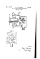
- Fig. 1 is a vertical section through a slip switch embodying my invention and through its enclosing casing and the adjacent part of an electric motor;
- Fig. 2 is a front elevation of the slip switch shown in Fig. 1, the casing being shown with the cover removed.
- the friction device is constructed and arranged the same as in my co-opending application hereinbefore referred to.
- a spindle 1 is threaded into the end of the shaft 2 of an electric motor a.
- a sleeve 3 is secured upon the spindle, and a cylinder of impregnated wood 4 is mounted so that it will turn upon the sleeve.
- Metal washers 5 and 6 are arranged at opposite sides of the cylinder, and these have tongues 5* and 6 respectively, which enter a keywa-y 7 in the sleeve, so that the washers will turn with the sleeve.
- the washer 5 fits against a shoulder 8 on the sleeve, and an endless helical spring 9 is held against the outer side of the washer 6 by a nut 10, which is threaded on. the sleeve and which has a conical outer surface on which the spring rests.
- a metal band 11 is afiixed to the periphery of the cylinder, and an arm 12 projects radially from the band and is adapted to engage fixed stops 13 and 14, which limit the movements of the cylinder and arm.
- a mercury switch I which, in Figs. 1 and 2 of the drawings, is secured to the band surrounding the wooden cylinder.
- This switch comprises a. curved glass tube 15, which is secured to the band 11 by metal clips 16, which extend around the ends of the tube.
- W'ire terminals 17 and 18 extend into the tube and these are connected by flexible conductors 17 and 18 to stationary binding posts 19 and 20, respectively.
- stops arranged to limit the movementoi said devicewith-the shaft to a partialrotatiom in either-directionof movement of the shaft and a mercury switchsecured to said device and adapted to rock therewith about the'axis of the shaft, when the direction of movement of the shaft is reversed.
Landscapes
- Engineering & Computer Science (AREA)
- Power Engineering (AREA)
- Stopping Of Electric Motors (AREA)
Description
' March 29, 1932. wHWTiNGHAM 1,851,227
FRICTION SW ITCH FOR ELECTRIC MOTOR CIRCUITS Filed necfzs, 1 929 Patented Mar. 29, 1932 UITED STATES PATENT OFFICE GEORGE H. WHITTINGHAM, OIE
BALTIMORE, MARYLAND, ASSIGN OR TO MONITOR CON- TROLLER COMPANY, OF BALTIMORE, MARYLAND,
A CORPORATION OF 'MARYLAND FRICTION SWITCH FOR ELECTRIC MOTOR CIRCUITS Application filed December 28, 1929. Serial No. 417,188.
This invention relates to a slip switch adapted for use in connection with alternating current induction motors, to control the circuit of a magnet which operates a reverse switch for reversing the current phases in the motor to cause the motor to stop quickly after the main switch has been opened. When the motor comes to a stop and starts to reverse, the slip switch opens the circuit of the magnet controlling the reverse switch and the lat- 'ter switch opens, cutting ofi' the braking current. A switch of this character is described in my co-pending application Serial Number 365,915; filed May 25, 1929. The friction de- 5- vice in the present application is substantially the same as that shown in the previous application, but in the present case the circuit closing and openings means consists of a mercury switch, which, is secured to the cylinder of 2 the friction device and rocks with it about the same axis.
In the accompanying drawings,
Fig. 1 is a vertical section through a slip switch embodying my invention and through its enclosing casing and the adjacent part of an electric motor; and
Fig. 2 is a front elevation of the slip switch shown in Fig. 1, the casing being shown with the cover removed.
In Fig. 1, the friction device is constructed and arranged the same as in my co-opending application hereinbefore referred to. A spindle 1 is threaded into the end of the shaft 2 of an electric motor a. A sleeve 3 is secured upon the spindle, and a cylinder of impregnated wood 4 is mounted so that it will turn upon the sleeve. Metal washers 5 and 6 are arranged at opposite sides of the cylinder, and these have tongues 5* and 6 respectively, which enter a keywa-y 7 in the sleeve, so that the washers will turn with the sleeve. The washer 5 fits against a shoulder 8 on the sleeve, and an endless helical spring 9 is held against the outer side of the washer 6 by a nut 10, which is threaded on. the sleeve and which has a conical outer surface on which the spring rests. By adjusting the nut in ward or outward, the spring pressure against the shoulder 6 may be varied, and the pressure or" the disks against the cylinder will be varied accordingly. A metal band 11 is afiixed to the periphery of the cylinder, and an arm 12 projects radially from the band and is adapted to engage fixed stops 13 and 14, which limit the movements of the cylinder and arm. With the arrangement described, when the motor is operated in one direction the arm 12 will engage the stop 14 and the washers will then slide on the cylinder, and when the motor turns in the opposite direction the cylinder will be moved, by its trictional engagement with the washers, until the arms engages the stop 13, when the movement of the cylinder will be arrested.
These limited movements of the friction device are utilized to make and break an electric circuit through the medium of a mercury switch I; which, in Figs. 1 and 2 of the drawings, is secured to the band surrounding the wooden cylinder. This switch comprises a. curved glass tube 15, which is secured to the band 11 by metal clips 16, which extend around the ends of the tube. W'ire terminals 17 and 18 extend into the tube and these are connected by flexible conductors 17 and 18 to stationary binding posts 19 and 20, respectively. When the motor is rotating in the direction indicated by the arrow in Fig. 2, the arm 12 rests against the stop 13, and in this position of the mercury switch the circuit is open between the terminals 17 and 18.
s soon as the motor starts to operate in the reverse direction, the frictionally driven cylinder turns until the arm 12 rests against the stop 14, and in this position of the cylinder the mercury in the tube electrically connects the terminals 17 and 18.
In stopping alternating current induction motors, it is common practice to open the main switch to disconnect the motor from the supply circuit and to then close a reverse current switch which reverses the current phases in the motor and causes a dynamic braking action which quickly slows the motor down. or before the time that the rotor of the motor comes to rest, it is necessary to open the reverse switch in order to prevent backward rotation of the motor. The reverse switch is usually closed by an electro magnet and the friction switch of my present invention is IOU utilized to cause the opening of the circuit of this magnet as soon as the motor commences I backward rotation after having been slowed down by dynamic brak ng.
What I claim is:
The; combination with ashaft adapted to be drivenby arreversible electric motor; ofa
device frictionally mounted on the shaft,
stopsarranged to limit the movementoi said devicewith-the shaft to a partialrotatiom in either-directionof movement of the shaft and a mercury switchsecured to said device and adapted to rock therewith about the'axis of the shaft, when the direction of movement of the shaft is reversed.
In testimony whereof I: affixmy signature.
I GEORGE H: WHIETIN-GHAM.
Priority Applications (1)
| Application Number | Priority Date | Filing Date | Title |
|---|---|---|---|
| US417188A US1851227A (en) | 1929-12-28 | 1929-12-28 | Friction switch for electric motor circuits |
Applications Claiming Priority (1)
| Application Number | Priority Date | Filing Date | Title |
|---|---|---|---|
| US417188A US1851227A (en) | 1929-12-28 | 1929-12-28 | Friction switch for electric motor circuits |
Publications (1)
| Publication Number | Publication Date |
|---|---|
| US1851227A true US1851227A (en) | 1932-03-29 |
Family
ID=23652940
Family Applications (1)
| Application Number | Title | Priority Date | Filing Date |
|---|---|---|---|
| US417188A Expired - Lifetime US1851227A (en) | 1929-12-28 | 1929-12-28 | Friction switch for electric motor circuits |
Country Status (1)
| Country | Link |
|---|---|
| US (1) | US1851227A (en) |
Cited By (4)
| Publication number | Priority date | Publication date | Assignee | Title |
|---|---|---|---|---|
| US2449799A (en) * | 1946-09-18 | 1948-09-21 | Alvarez Patent Corp | Switch arrangement |
| US2676717A (en) * | 1952-11-18 | 1954-04-27 | Joy Mfg Co | Centering mechanism for the shovel of shovel loaders |
| US2825776A (en) * | 1955-05-06 | 1958-03-04 | Guy A Curtis | Overload cutout switch |
| US3296403A (en) * | 1962-09-28 | 1967-01-03 | Ingram Maxwell | Means for operating a rotation indicating switch |
-
1929
- 1929-12-28 US US417188A patent/US1851227A/en not_active Expired - Lifetime
Cited By (4)
| Publication number | Priority date | Publication date | Assignee | Title |
|---|---|---|---|---|
| US2449799A (en) * | 1946-09-18 | 1948-09-21 | Alvarez Patent Corp | Switch arrangement |
| US2676717A (en) * | 1952-11-18 | 1954-04-27 | Joy Mfg Co | Centering mechanism for the shovel of shovel loaders |
| US2825776A (en) * | 1955-05-06 | 1958-03-04 | Guy A Curtis | Overload cutout switch |
| US3296403A (en) * | 1962-09-28 | 1967-01-03 | Ingram Maxwell | Means for operating a rotation indicating switch |
Similar Documents
| Publication | Publication Date | Title |
|---|---|---|
| US1851227A (en) | Friction switch for electric motor circuits | |
| US2528489A (en) | Indexing mechanism | |
| US1222720A (en) | Automatic switch. | |
| US2502167A (en) | Control system for electrical motors | |
| US2307204A (en) | Electric windshield wiper | |
| US2473244A (en) | Dynamoelectric machine | |
| US1754072A (en) | Extensible electric conductor | |
| US2327959A (en) | Valve operating means | |
| US2144416A (en) | Armature brake | |
| US1997690A (en) | Device for winding hair | |
| US2479975A (en) | Control device for turntables | |
| US1580161A (en) | Starting switch for motors | |
| US1549234A (en) | Winding device for spring motors | |
| US1794961A (en) | Control system | |
| US1781762A (en) | Variable-speed control for electric motors | |
| US2232363A (en) | Electric motor | |
| US1551794A (en) | Electrical apparatus | |
| US2181841A (en) | Motor and motor-operated apparatus | |
| US2330648A (en) | Reversing split phase motor control | |
| US1691433A (en) | Phase-failure and phase-reversal protector | |
| US1438891A (en) | Electrical control for winding spring motors | |
| US1870896A (en) | Automatic circuit breaking switch | |
| US1433707A (en) | Control switch for electric motors | |
| US2555097A (en) | Self-starting single-phase motor | |
| US2030277A (en) | Torque motor |