US1851221A - Apparatus for supplying fuel to internal combustion engines, etc. - Google Patents
Apparatus for supplying fuel to internal combustion engines, etc. Download PDFInfo
- Publication number
- US1851221A US1851221A US325958A US32595828A US1851221A US 1851221 A US1851221 A US 1851221A US 325958 A US325958 A US 325958A US 32595828 A US32595828 A US 32595828A US 1851221 A US1851221 A US 1851221A
- Authority
- US
- United States
- Prior art keywords
- fuel
- chamber
- float
- valve
- heated
- Prior art date
- Legal status (The legal status is an assumption and is not a legal conclusion. Google has not performed a legal analysis and makes no representation as to the accuracy of the status listed.)
- Expired - Lifetime
Links
- 239000000446 fuel Substances 0.000 title description 46
- 238000002485 combustion reaction Methods 0.000 title description 4
- 239000003350 kerosene Substances 0.000 description 12
- 238000010438 heat treatment Methods 0.000 description 9
- 238000005266 casting Methods 0.000 description 7
- 230000001276 controlling effect Effects 0.000 description 4
- OKTJSMMVPCPJKN-UHFFFAOYSA-N Carbon Chemical compound [C] OKTJSMMVPCPJKN-UHFFFAOYSA-N 0.000 description 1
- 229910052799 carbon Inorganic materials 0.000 description 1
- 230000007423 decrease Effects 0.000 description 1
- 239000007789 gas Substances 0.000 description 1
- 239000000203 mixture Substances 0.000 description 1
- 230000001105 regulatory effect Effects 0.000 description 1
- 230000000284 resting effect Effects 0.000 description 1
Images

Classifications
-
- F—MECHANICAL ENGINEERING; LIGHTING; HEATING; WEAPONS; BLASTING
- F02—COMBUSTION ENGINES; HOT-GAS OR COMBUSTION-PRODUCT ENGINE PLANTS
- F02M—SUPPLYING COMBUSTION ENGINES IN GENERAL WITH COMBUSTIBLE MIXTURES OR CONSTITUENTS THEREOF
- F02M1/00—Carburettors with means for facilitating engine's starting or its idling below operational temperatures
-
- F—MECHANICAL ENGINEERING; LIGHTING; HEATING; WEAPONS; BLASTING
- F02—COMBUSTION ENGINES; HOT-GAS OR COMBUSTION-PRODUCT ENGINE PLANTS
- F02M—SUPPLYING COMBUSTION ENGINES IN GENERAL WITH COMBUSTIBLE MIXTURES OR CONSTITUENTS THEREOF
- F02M13/00—Arrangements of two or more separate carburettors; Carburettors using more than one fuel
- F02M13/06—Arrangements of two or more separate carburettors; Carburettors using more than one fuel the carburettors using different fuels
-
- F—MECHANICAL ENGINEERING; LIGHTING; HEATING; WEAPONS; BLASTING
- F02—COMBUSTION ENGINES; HOT-GAS OR COMBUSTION-PRODUCT ENGINE PLANTS
- F02M—SUPPLYING COMBUSTION ENGINES IN GENERAL WITH COMBUSTIBLE MIXTURES OR CONSTITUENTS THEREOF
- F02M2700/00—Supplying, feeding or preparing air, fuel, fuel air mixtures or auxiliary fluids for a combustion engine; Use of exhaust gas; Compressors for piston engines
- F02M2700/43—Arrangements for supplying air, fuel or auxiliary fluids to a combustion space of mixture compressing engines working with liquid fuel
- F02M2700/4302—Arrangements for supplying air, fuel or auxiliary fluids to a combustion space of mixture compressing engines working with liquid fuel whereby air and fuel are sucked into the mixture conduit
- F02M2700/4314—Arrangements for supplying air, fuel or auxiliary fluids to a combustion space of mixture compressing engines working with liquid fuel whereby air and fuel are sucked into the mixture conduit with mixing chambers disposed in parallel
- F02M2700/4316—Arrangements for supplying air, fuel or auxiliary fluids to a combustion space of mixture compressing engines working with liquid fuel whereby air and fuel are sucked into the mixture conduit with mixing chambers disposed in parallel without mixing chambers disposed in parallel
Definitions
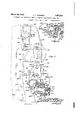
- Fig. 1 is a side elevation, parts being broken away to show the feeding and control mechanism for bothlight and heavy fuel;
- Fig. 2 is a plan view of the same, parts beconstruction and easy ing broken away;
- Fig. 3 is an end elevation, parts being sectional on the line 3-3 of Fig. 1;
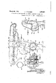
- Fig. 4 is 'a detail section of the regulatory valve connecting the gasoline and kerosene float-chambers with the mixing chamber;
- Fig. 5 is a side elevation of the manifold with the carbureter and other mechanism removed;
- Fig. 6 is a section on the line 66 of Fig. 5;
- Fig. 7 is a detail section of the kerosene float-chamber on the line 7 7 of Fig. 1; and FFig. 8 is a detail section on the line 88 'of
- the engine manifold (Figs. 2, 3 and 5) is provided with exhaust ports 92 and intake ports 91 and connected to the manifold at 86' is a casting comprising the vertical portion 94 through which the exhaust gases pass downwardly and a lateral branch 86 through which the fuel mixture flows to the intake ports 91 through the passageways 87 and 89 (Figs. 5 and 6).
- Surrounding the vertical portion 94 is an integral jacket forming an annular fuel heating chamber 96. Fuel is supplied to this chamber through pipe 98 and the chamber is vented through pipe 101 (Figs. 1, 2, 3 and 5). This heating chamber is provided with an uas'sacnusnrrs,
- the carbureter casting comprises a kerosene float-chamber 107, gasoline float chamber 137 and a mixing chamber 82. All of these chambers are cast integrally together, the chambers 82 and 107 being integrally connected at 164 and 163 (Figs. 1 and 8).
- the upper end 83 of the mixing chamber 82 is connected to the end 85 of the aforesaid portion 86 (Fig. 3). Air is introduced-into the mixing chamber through the air intake 80 (Figs. 1, 2 and 3) and the lower portion 81 (Fig. 2) of the carbureter casting.
- the kerosene float-chamber 107 is provided with a double wall thus forming a jacket chamber 108 which communicates with the heating chamber 96 through the opening through the jacket of the float-chamber in the direction indicated by the arrows in Fig. 7, thereby heating the float-chamber and maintaining a considerable supply of heated fuel at all times.
- Fuel flows from the jacket chamber 108 into the float-chamber through passageway (Fig. 7) controlledb nee le valve 105 which in turn is controlled by the float 100.
- Heated kerosene flows from the float-chamber to the mixing chamber through a duct 116 (Figs. 1, 4 and 8) thence through valve chamber 119 and thence through duct 124 (Figs. 3 and 4).
- Gasoline flows from the float-chamber 137 through the duct 140 (Figs 1 and 4) to the valve chamber 119 and thence through duct 124 to the mixing chamber.
- the valve shaft 123 is controlled by the three-arm member 114 (Fig. 1) on the outside of the valve chamber.
- the upper arm is connected through sprin 151 to lever 147 pivoted at 148 and norma ly resting against a stop 149.
- the lower arm of member 114 is connected with the choke control through arm 162, spring 161 and arm 158 mounted on the lower end of the choke valve shaft, this valve being controlled in the usual way through arm 156 and a connection 159 leading to the instrument board (Figs. 1 and 2).
- a cam lever 157 may also be associated with the choke to adjust the valve.
- the horizontal arm of member 114 (Fig. 1)
- thermostatic disk 111 is mounted in the lower portion of the jacket chamber 108 so that it is immersed in the heated fuel, openings through the disk being provided as shown in Fig. 1 to permit the fuel to flow therethrough and equalize the pressure on opp site sides of the disk. is so constructed that it normally cups downwardly in the middle and when heated to a predetermined temperature suddenly snaps upwardly to a position wherein it is cupped upwardly in the middle.
- valve 121 is held in the position shown in Fig. 4 wherein gasoline is admitted to the mixing chamber and the kerosene is shut off.
- the thermostatic disk 111 snaps upwardly thereby shifting the valve to its lower position (Fig. 4) whereupon the gasoline is shut off and heated kerosene is admitted to the mixing chamber.
- the springs 113, 151 and 161 actgasoline position independently of the position of the thermostat.
- the reservoir of kerosene Within the floatchamber is maintained in proper condition for delivery to the mixing chamber.
- the thermostat is immersed in the heated fuel and is therefore quickly responsive to change in the temperature of the fuel. All of the conduits for the heated fuel are inside the associated castings so that substantially no chilling takes place as in apparatus where the heated fuel is conducted through exposed pipes.
- Fuel supply apparatus comprising a fuel conduit including a float-chamber, means for heating the fuel before it leaves said float chamber, and a thermostat in heat-contacting relationship to said float-chamber for interrupting the flow of fuel from the chamber between full open and closed controlling the flow of fuel when the temperature of the fuel decreases below a predetermined point.
- Apparatus for supplying fuel to a device comprising a fuel reservoir, a conduit connecting said reservoir with said device, a float-chamber in said conduit, means for heating the fuel while it is in the float-chamr, and means responsve to the temperature of the fuel to the float-chamber and said device for controlling the flow'of fuel from the float-chamber to the device.
- Apparatus for supplying heated fuel to a device comprising a fuel reservoir, a floatchamber, a jacket for said chamber, a circuitous conduit including the space between said chamber and said jacket, means for conducting fuel from said reservoir to said conduit and thence through said float-chamber to said device, and thermo-syphon means for heating the fuel in said conduit and therey continuously circulating the heated fuel around said float-chamber.
- Apparatus for supplying heated fuel to a device comprising a fuel reservoir, a floatchamber, a jacket for said chamber, acircuitous conduit including the space between said chamber and said jacket, means for conducting fuel from said reservoir to said conduit and thence through said float-chamber to said device, thermal means the temperature of said fuel for controlling its flow to said device, and means for heating the fuel in said conduit and thereby continuously circulating the heated fuel through said circuitous conduit independently of fuel flow to said device.
Landscapes
- Engineering & Computer Science (AREA)
- Chemical & Material Sciences (AREA)
- Combustion & Propulsion (AREA)
- Mechanical Engineering (AREA)
- General Engineering & Computer Science (AREA)
- Output Control And Ontrol Of Special Type Engine (AREA)
Description
Man-ch29, 1932. 1.1-. THURBER' APPARATUS FOR SUPPLYING FUEL T0 INLIERNAL COIBUSTION ENGINES, ETC
P Original Filed Oct: 3, 192: a Sheets-Sheet 1 Medea? L. "r. THURBER' March 29, 1932,
APPARATUS FOR SUPPLYING FUEL TO INTERNALCOMBUSTION ENGINES, ETC
Original Filed Oct. 3, 1923 3 Sheets-Sheet 2 f 11 .2 W. ,erelor' L. T. THURBER March 29, 193.2.
APPARATUS FOR SUPPLYING FUEL TO INTERNAL cousus'riou memns, ETC
3 Sheets-Sheet 3 Original Filed Oct. 3, 1923 ill L111 ,lxl III III combustion engines and which is generally posit in the engine,
' application Patented Mar. 29,. 1932 HUMAN T. THUBBEB, OF BBOOKLINE,
ATOB. CORPORATION, OF EOCKLAND, MAINE, A CORPORATION APPARATUS Original application Objects of the present invention are to .provide apparatus for supplying fuel to internal which permits the use of heavy fuel, which conditions the fuel for eflicient combustion, which avoids carbon dewhich is economical in to install and repair, superior to apparatus heretofore proposed for the purpose. This is a division of my application, Serial No. 667,062, filed October 6, 1923, which has since matured into Patent No. 1,77 6,87 1 dated September 30, 1930.
For the purpose of illustrating the genus of the invention a concrete embodiment is shown in the accompanying drawings in which Fig. 1is a side elevation, parts being broken away to show the feeding and control mechanism for bothlight and heavy fuel;
Fig. 2 is a plan view of the same, parts beconstruction and easy ing broken away;
Fig. 3 is an end elevation, parts being sectional on the line 3-3 of Fig. 1;
Fig. 4 is 'a detail section of the regulatory valve connecting the gasoline and kerosene float-chambers with the mixing chamber;
Fig. 5 is a side elevation of the manifold with the carbureter and other mechanism removed;
Fig. 6 is a section on the line 66 of Fig. 5;
Fig. 7 is a detail section of the kerosene float-chamber on the line 7 7 of Fig. 1; and FFig. 8 is a detail section on the line 88 'of In the embodiment shown in the drawings the engine manifold (Figs. 2, 3 and 5) is provided with exhaust ports 92 and intake ports 91 and connected to the manifold at 86' is a casting comprising the vertical portion 94 through which the exhaust gases pass downwardly and a lateral branch 86 through which the fuel mixture flows to the intake ports 91 through the passageways 87 and 89 (Figs. 5 and 6). Surrounding the vertical portion 94 is an integral jacket forming an annular fuel heating chamber 96. Fuel is supplied to this chamber through pipe 98 and the chamber is vented through pipe 101 (Figs. 1, 2, 3 and 5). This heating chamber is provided with an uas'sacnusnrrs,
FOR SUPPLYING FUEL TO INTERNAL COMBUSTION ASSIGNOB TO THE THUBBER- OF MAINE ENGINES, n'rc.
filed October 6, 1923, Serial No. 667,062. Divided and this application filed December 14, 1928. Serial No. 325,958.
opening 104 on the outer side (Figs. 5 and 7) and the carbureter casting is mounted over this, opening at the joint 102 (Fig. 7), the ioint preferably being of the conical type as illustrated. The carbureter casting comprises a kerosene float-chamber 107, gasoline float chamber 137 and a mixing chamber 82. All of these chambers are cast integrally together, the chambers 82 and 107 being integrally connected at 164 and 163 (Figs. 1 and 8). The upper end 83 of the mixing chamber 82 is connected to the end 85 of the aforesaid portion 86 (Fig. 3). Air is introduced-into the mixing chamber through the air intake 80 (Figs. 1, 2 and 3) and the lower portion 81 (Fig. 2) of the carbureter casting.
The kerosene float-chamber 107 is provided with a double wall thus forming a jacket chamber 108 which communicates with the heating chamber 96 through the opening through the jacket of the float-chamber in the direction indicated by the arrows in Fig. 7, thereby heating the float-chamber and maintaining a considerable supply of heated fuel at all times. Fuel flows from the jacket chamber 108 into the float-chamber through passageway (Fig. 7) controlledb nee le valve 105 which in turn is controlled by the float 100. Heated kerosene flows from the float-chamber to the mixing chamber through a duct 116 (Figs. 1, 4 and 8) thence through valve chamber 119 and thence through duct 124 (Figs. 3 and 4).
Gasoline flows from the float-chamber 137 through the duct 140 (Figs 1 and 4) to the valve chamber 119 and thence through duct 124 to the mixing chamber. A valve 121 mounted on arm 122 (Fig. 4) which is pivoted at 123 controls the kerosene and gasoline outlet-s .118 and 141 to the valve chamoer 119, the kerosene being shut off when the valve is rotated in a counter-clockwise direction to the position shown in Fig. 4
and the gasoline being shut off when the valve is rotated in a clockwise direction. The valve shaft 123 is controlled by the three-arm member 114 (Fig. 1) on the outside of the valve chamber. The upper arm is connected through sprin 151 to lever 147 pivoted at 148 and norma ly resting against a stop 149. The lower arm of member 114 is connected with the choke control through arm 162, spring 161 and arm 158 mounted on the lower end of the choke valve shaft, this valve being controlled in the usual way through arm 156 and a connection 159 leading to the instrument board (Figs. 1 and 2). A cam lever 157 may also be associated with the choke to adjust the valve. The horizontal arm of member 114 (Fig. 1) is connected through the spring 113 to the lever 112' which is connected at its opposite end through pin 109 to a thermostatic disk 111. This disk, which is preferably of the concave-convex bimetallic type disclosed in the platent to Spencer No. 1,448,240, is mounted in the lower portion of the jacket chamber 108 so that it is immersed in the heated fuel, openings through the disk being provided as shown in Fig. 1 to permit the fuel to flow therethrough and equalize the pressure on opp site sides of the disk. is so constructed that it normally cups downwardly in the middle and when heated to a predetermined temperature suddenly snaps upwardly to a position wherein it is cupped upwardly in the middle. Thus in the normal position of the thermostat shown in Fig. 1 the valve 121 is held in the position shown in Fig. 4 wherein gasoline is admitted to the mixing chamber and the kerosene is shut off. However, after the engine is started and the kerosene in the float-chamber becomes heated to the desired temperature the thermostatic disk 111 snaps upwardly thereby shifting the valve to its lower position (Fig. 4) whereupon the gasoline is shut off and heated kerosene is admitted to the mixing chamber. The springs 113, 151 and 161 actgasoline position independently of the position of the thermostat.
wing to the continuous circulation of heated fuel around the kerosene float-chamber, the reservoir of kerosene Within the floatchamber is maintained in proper condition for delivery to the mixing chamber. to the close juxtaposition and direct connection between the exhaust casting 94 and the carbnreter casting, the latter heats up quicker and is more easily maintained in heated condition. The thermostat is immersed in the heated fuel and is therefore quickly responsive to change in the temperature of the fuel. All of the conduits for the heated fuel are inside the associated castings so that substantially no chilling takes place as in apparatus where the heated fuel is conducted through exposed pipes.
1. ue su a ara us com rism aconduit includiiigzi f l at chambei' mefns for heating the fuel while it is in the float chamber, a valve for controlling the flow of fuel from the float chamber, this valve being operable between full open and closed positions, and means responsive to the temperaing the valve positions for therefrom.
2. Fuel supply apparatus comprising a fuel conduit including a float-chamber, means for heating the fuel before it leaves said float chamber, and a thermostat in heat-contacting relationship to said float-chamber for interrupting the flow of fuel from the chamber between full open and closed controlling the flow of fuel when the temperature of the fuel decreases below a predetermined point.
3. Apparatus for supplying fuel to a device comprising a fuel reservoir, a conduit connecting said reservoir with said device, a float-chamber in said conduit, means for heating the fuel while it is in the float-chamr, and means responsve to the temperature of the fuel to the float-chamber and said device for controlling the flow'of fuel from the float-chamber to the device.
4. Apparatus for supplying heated fuel to a device comprising a fuel reservoir,a floatchamber, a jacket for said chamber, a circuitous conduit including the space between said chamber and said jacket, means for conducting fuel from said reservoir to said conduit and thence through said float-chamber to said device, and thermo-syphon means for heating the fuel in said conduit and therey continuously circulating the heated fuel around said float-chamber.
5. Apparatus for supplying heated fuel to a device comprising a fuel reservoir, a floatchamber, a jacket for said chamber, acircuitous conduit including the space between said chamber and said jacket, means for conducting fuel from said reservoir to said conduit and thence through said float-chamber to said device, thermal means the temperature of said fuel for controlling its flow to said device, and means for heating the fuel in said conduit and thereby continuously circulating the heated fuel through said circuitous conduit independently of fuel flow to said device.
Signed by me at Boston, Massachusetts, this 24th day of November, 1928.
UMAN T. THURBER.
at a point between the inlet responsive to
Priority Applications (1)
| Application Number | Priority Date | Filing Date | Title |
|---|---|---|---|
| US325958A US1851221A (en) | 1923-10-06 | 1928-12-14 | Apparatus for supplying fuel to internal combustion engines, etc. |
Applications Claiming Priority (2)
| Application Number | Priority Date | Filing Date | Title |
|---|---|---|---|
| US667062A US1776871A (en) | 1923-10-06 | 1923-10-06 | Apparatus for supplying fuel to internal-combustion engines |
| US325958A US1851221A (en) | 1923-10-06 | 1928-12-14 | Apparatus for supplying fuel to internal combustion engines, etc. |
Publications (1)
| Publication Number | Publication Date |
|---|---|
| US1851221A true US1851221A (en) | 1932-03-29 |
Family
ID=26985182
Family Applications (1)
| Application Number | Title | Priority Date | Filing Date |
|---|---|---|---|
| US325958A Expired - Lifetime US1851221A (en) | 1923-10-06 | 1928-12-14 | Apparatus for supplying fuel to internal combustion engines, etc. |
Country Status (1)
| Country | Link |
|---|---|
| US (1) | US1851221A (en) |
-
1928
- 1928-12-14 US US325958A patent/US1851221A/en not_active Expired - Lifetime
Similar Documents
| Publication | Publication Date | Title |
|---|---|---|
| US1966345A (en) | Hydrogen generator for internal combustion engines | |
| US1448008A (en) | Heat control of mixture for internal-combustion engines | |
| US2074471A (en) | Thermostatic control of automobile engine fuel | |
| US1851221A (en) | Apparatus for supplying fuel to internal combustion engines, etc. | |
| US1776871A (en) | Apparatus for supplying fuel to internal-combustion engines | |
| US2702536A (en) | Automatic choke control | |
| US2715520A (en) | Carburetor de-icing means | |
| US1413985A (en) | Carburetor air-control device | |
| US2236032A (en) | Automatic fuel control for internal combustion engines | |
| US2030331A (en) | Carburetor | |
| US2093961A (en) | Automatic carburetor | |
| US1781356A (en) | Vapor-supplying attachment | |
| US2098575A (en) | System for feeding fuels to internal combustion machines | |
| US1221956A (en) | Carbureter. | |
| US1998497A (en) | Automatic heat control for carburetors | |
| US1694759A (en) | Thermostatic control of carburetors | |
| US1304888A (en) | Automatic control for internal-combustion engines | |
| US1867457A (en) | Charge forming device for internal combustion engines | |
| US1635266A (en) | davenport | |
| US1487234A (en) | Carburetor | |
| US1408671A (en) | Charge-forming device | |
| US1278900A (en) | Auxiliary hot-air and moisture device. | |
| US1580962A (en) | Vapor-supply system for internal-combustion engines | |
| US1800426A (en) | Heat-control apparatus for intake gases of internal-combustion engines | |
| US1467225A (en) | Fuel heater for internal-combustion engines |