US1851213A - Safety screw with tightening pressure - Google Patents
Safety screw with tightening pressure Download PDFInfo
- Publication number
- US1851213A US1851213A US394885A US39488529A US1851213A US 1851213 A US1851213 A US 1851213A US 394885 A US394885 A US 394885A US 39488529 A US39488529 A US 39488529A US 1851213 A US1851213 A US 1851213A
- Authority
- US
- United States
- Prior art keywords
- nut
- ring
- pin
- sliding way
- slit
- Prior art date
- Legal status (The legal status is an assumption and is not a legal conclusion. Google has not performed a legal analysis and makes no representation as to the accuracy of the status listed.)
- Expired - Lifetime
Links
- 208000032825 Ring chromosome 2 syndrome Diseases 0.000 description 19
- 238000010276 construction Methods 0.000 description 9
- 239000003659 bee venom Substances 0.000 description 1
- VDXZNPDIRNWWCW-JFTDCZMZSA-N melittin Chemical compound NCC(=O)N[C@@H]([C@@H](C)CC)C(=O)NCC(=O)N[C@@H](C)C(=O)N[C@@H](C(C)C)C(=O)N[C@@H](CC(C)C)C(=O)N[C@@H](CCCCN)C(=O)N[C@@H](C(C)C)C(=O)N[C@@H](CC(C)C)C(=O)N[C@@H]([C@@H](C)O)C(=O)N[C@@H]([C@@H](C)O)C(=O)NCC(=O)N[C@@H](CC(C)C)C(=O)N1CCC[C@H]1C(=O)N[C@@H](C)C(=O)N[C@@H](CC(C)C)C(=O)N[C@@H]([C@@H](C)CC)C(=O)N[C@@H](CO)C(=O)N[C@H](C(=O)N[C@@H]([C@@H](C)CC)C(=O)N[C@@H](CCCCN)C(=O)N[C@@H](CCCNC(N)=N)C(=O)N[C@@H](CCCCN)C(=O)N[C@@H](CCCNC(N)=N)C(=O)N[C@@H](CCC(N)=O)C(=O)N[C@@H](CCC(N)=O)C(N)=O)CC1=CNC2=CC=CC=C12 VDXZNPDIRNWWCW-JFTDCZMZSA-N 0.000 description 1
- 238000010079 rubber tapping Methods 0.000 description 1
Images
Classifications
-
- F—MECHANICAL ENGINEERING; LIGHTING; HEATING; WEAPONS; BLASTING
- F16—ENGINEERING ELEMENTS AND UNITS; GENERAL MEASURES FOR PRODUCING AND MAINTAINING EFFECTIVE FUNCTIONING OF MACHINES OR INSTALLATIONS; THERMAL INSULATION IN GENERAL
- F16B—DEVICES FOR FASTENING OR SECURING CONSTRUCTIONAL ELEMENTS OR MACHINE PARTS TOGETHER, e.g. NAILS, BOLTS, CIRCLIPS, CLAMPS, CLIPS OR WEDGES; JOINTS OR JOINTING
- F16B39/00—Locking of screws, bolts or nuts
- F16B39/02—Locking of screws, bolts or nuts in which the locking takes place after screwing down
-
- Y—GENERAL TAGGING OF NEW TECHNOLOGICAL DEVELOPMENTS; GENERAL TAGGING OF CROSS-SECTIONAL TECHNOLOGIES SPANNING OVER SEVERAL SECTIONS OF THE IPC; TECHNICAL SUBJECTS COVERED BY FORMER USPC CROSS-REFERENCE ART COLLECTIONS [XRACs] AND DIGESTS
- Y10—TECHNICAL SUBJECTS COVERED BY FORMER USPC
- Y10S—TECHNICAL SUBJECTS COVERED BY FORMER USPC CROSS-REFERENCE ART COLLECTIONS [XRACs] AND DIGESTS
- Y10S411/00—Expanded, threaded, driven, headed, tool-deformed, or locked-threaded fastener
- Y10S411/955—Locked bolthead or nut
Definitions
- the invention refers to a safety nut which can also be used as a lock-nut.
- the novelty of the invention consists in the fact that a ring,,tapped and slit, is fitted ifil'into an annular groove provided at the bottom face of the nut in such a way that it exceeds the groove, the ring being provided,
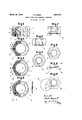
- Fig. 1 shows a view inclevation and the left half shows a section through the whole of the nut.
- Fig.2 shows on the right side, the plan ofthe nut seen from the top and on the left side, a section according to the line I of Fig. 1 with Fig. 3 shows onthe right side the plan of the nut seen from'the bottom and on the left side a section similarto that of Fig. 2 with the'ring placed inthe, position of a lock-nut.
- Fig. 4 is a draught showing the nut in an intermediate position, the right half of it being the plan seen from the. top and the left half, a ring similar to that of Fig. 3.
- the Figs. 5 to 10 s how,'on a differentscale, two other forms of construction of the joining device of the body ofthe nut with the ring.
- I Fig. 5 is an elevation and Fig. 6 a plane view of a nut providedwith a joining device by radial split-pin. a I
- Figs. 7 to 10 show another formof construction of a joining device.
- aislidingway 3 is fitted, formed, the bottom of which is eccentric and extendsprogressively from the inner periphery of the annular groove of the body ofthe nut, from a point near" the slit to the end or the sliding way.
- the height of the i ring slightly exceeds the depthof the'groove in which it is fitted, so that the ring projects slightly beyond the inner face of the nut.
- a locking pin at is fitted .inthe body of the nutpoverstriding the latter and the "sliding way.
- the slit 5 mentioned above divides the ring'2, making it thus” elastic. It is placed quite near the beginning of the slid- V ing way 3.
- the nut can beused either as a safety nut or as a lock-nut according to whether the ring.
- the ring-2 is placed in the groove of the body of the nut withthe slit 5 in front of the sliding way 3, with regard to'the direction of rotation of the nut shown by the arrow 6.
- the bodyl of the screw goes on screwing in the direction of the arrow 6 and the pin 4 movesforward on the sliding way 3 until it reaches the end of the 9 ring 2,-quite near'the slit 5.
- the pressure exerted by the pin 4 on that end of the ring engages said end with the thread of the bolt and also looks the ring 2 to the bodyof the nut.
- the nut is thus screwed onto the bolt and can by no means get casually unscrewed.
- the ring 2 acts in some degree like an elastic washer (ring of Grower) with the difference that in the present case, the fastening is done laterally. This lateral pressure being done in full, produces a complete fixation of the nut which cannot be unlocked.
- the position of the ring 2 is reverse in the annular groove of the body 1, that is to say the ring 2 is put in such a way that the sliding way will be in front of the slit 5 when the nut is viewed as before, in the direction of the arrow 6.
- the ring 2 can easily be taken off in screwing it to a bolt, for instance at the height of one thread and by hitting slightly against it in order to release it.
- a stop-recess can be provided at the end of the sliding way and near the slit 5 5, this recess keeps back the pin 4 in the ti htened position of the nut.
- the sliding way can be provided with one or more recesses 3, so that when there is a small play between the nut and the bolt or when the fastening cannot be carried out until the last recess,'the pin 4 can be held back by one of these recesses.
- a joining device is to be provided allowing the joining of the ring with the body of the screw, in order to unscrew them together.
- FIG. 3 A first form of construction of such a device is shown in Figs. 3 and 4.
- holes 7 and 8 are bored through and through; for instance at an angle of 120 or180 with the pin 4,
- a pin 1O is introduced into the holes 7 and 8 and the two devices 1 and 2 are thus joined.
- the ring can be unfastened by unscrewing the nut with a wrench, in the opposite direction of the arrow 9 and the nut 1 may be taken off with its inner ring 2 without damaging the threads of the bolt or of the nut.
- the holes 7 and 8 instead of being axial, can be bored in the radial direction, as shown in Figs. 5 and 6. Sufficient that this boring should pass through the body of the screw and the ring in their initial positions.
- the holes 11 and 12 have to receive the joining-pin which enables them to join and to unfasten them together in the same way as described in the precedent form of construction.
- a screw-nail can be used instead of the pin 10.
- the tapping must pass through the holes 7 and 8, respectively, 11 and 12.
- the length of the screw-nail can be equal to the length of the two holes 7 and 8 or only a part of those, so that when joining the two devices, there is but to screw the pin into the 'I he Figs. 7 to 10 show another form of construction of the joining device, based on the form given to the elastic ring.
- the projecting part of the ring exceeding the bottom face of the nut can have the shape of a hexagon bridle 0r washer 13, of the same dimensions as the hexagon nut.
- the part 14 bearing the sliding way, is separated from the bottom of the ring, which can be very easily obtained by means of a shim 15, shown in Fig. 10.
- the slit 16 (Fig. 9) thus obtained, gives the part 14 the necessary elasticity.
- the body of the nut will be blocked as for the precedent form of construction, until it is brought back to its initial position, in which the hexagon nut corresponds to that of the rin
- the wrench is applied simultaneously on lioth'parts and the whole of the nut and its ring can be easily unfastened.
- a nut having a threaded bore and an annular groove on its inner side concentric with the bore and a stop recess at one side of said groove in combination with a split ring revolubly fitted in said, groove, having an 1nterior thread corresponding with that of the nut and also having in'its outer periphery a sliding way spaced from the split portion of the ring and the bottomof which is eccentric 1 when the nut is turned against resistance of with the ring so that said sliding way deepens in one direction and a pin fitted in said recess of the nut and insaid sliding way, so that the ringathe end of said ring provided with said sliding way is moved by the camming action of the pin and the eccentric bottom of the sliding way radially inwardly and hence caused to lock the ring and the nut on a bolt onwhich the nut is screwed.
Landscapes
- Engineering & Computer Science (AREA)
- General Engineering & Computer Science (AREA)
- Mechanical Engineering (AREA)
- Details Of Spanners, Wrenches, And Screw Drivers And Accessories (AREA)
Description
' March 29, 1932.
P. ROSSET SAFETY SCREW WITH TIGHTENING .PRESSURE Filed Sept. 24, 1929 Patented. Mar. '29, 1932 PATENT SAFETY SCREW WITH TIGHTENIIN'G PRESSURE Application filed September -24, 1929,,Seria1 No. 394,885, and inswitzeriana ombu- ;1, 1 92s.
- The invention refers to a safety nut which can also be used as a lock-nut. o
The novelty of the invention consists in the fact that a ring,,tapped and slit, is fitted ifil'into an annular groove provided at the bottom face of the nut in such a way that it exceeds the groove, the ring being provided,
near the slit, with a's'liding way fora pin.
.the'ring 2 is fitted, this ring-being threaded The 60 threadingof the ring is the same as that of 7 fitted between the groove and the ring,'this way straying progressively from theslit, from the annular groove, all'those devices being assembled in such a way that a safety nut is obtained when theelastic ring is placed in the annular groove of the body of the nut, with the slit preceding the slidingway-w ith regard to'the direction of fastening, while, placing the ring in such a way that the slit is behind the sliding way, always with regard to the direction of fastening, a lock-nut F is obtained, which canbe unscrewed only by destroying the threadof the bolt, unless employing a joining device which allows the simultaneous unscrewing of thebody of the nut and the ring. g V
The annexeddrawings, given for example, show several forms of construction of .theinvention. V o
Therig'ht half of Fig. 1 shows a view inclevation and the left half shows a section through the whole of the nut.
Fig.2 shows on the right side, the plan ofthe nut seen from the top and on the left side, a section according to the line I of Fig. 1 with Fig. 3 shows onthe right side the plan of the nut seen from'the bottom and on the left side a section similarto that of Fig. 2 with the'ring placed inthe, position of a lock-nut. "Fig. 4: is a draught showing the nut in an intermediate position, the right half of it being the plan seen from the. top and the left half, a ring similar to that of Fig. 3. p The Figs. 5 to 10 s how,'on a differentscale, two other forms of construction of the joining device of the body ofthe nut with the ring. I Fig. 5 is an elevation and Fig. 6 a plane view of a nut providedwith a joining device by radial split-pin. a I
The Figs. 7 to 10 show another formof construction of a joining device. I
the ring placed in the position of a safety nut.
10 a plan of the elastic ring.
' In the form of "construction showedflin Figs. 1 to gum safety nut consists in abody properly'so called 1, the bottom of which .is provided withan annular groove .iinwhich' and slit in orderto becomeelastic.
the body of the nut. On one part'of the cylindrical face of the ring, aislidingway 3is fitted, formed, the bottom of which is eccentric and extendsprogressively from the inner periphery of the annular groove of the body ofthe nut, from a point near" the slit to the end or the sliding way. The height of the i ring slightly exceeds the depthof the'groove in which it is fitted, so that the ring projects slightly beyond the inner face of the nut. I
A locking pin at is fitted .inthe body of the nutpoverstriding the latter and the "sliding way. The slit 5 mentioned above divides the ring'2, making it thus" elastic. It is placed quite near the beginning of the slid- V ing way 3.
r The nut can beused either as a safety nut or as a lock-nut according to whether the ring.
2 isplacedin the annular groove .of thebody 80. of the nut 1, with the slit 5 before or behind the sliding way 3, with regardto the direction of tightening showed in Fig. 2 by the arrow 6. I
In the first caseshown in Fig. 2, the ring-2 is placed in the groove of the body of the nut withthe slit 5 in front of the sliding way 3, with regard to'the direction of rotation of the nut shown by the arrow 6. After the opposing face 'of the ring 2, while screwing, comes next tothe bottom surface of the object which is tobe fastened,.the bodyl of the screw goes on screwing in the direction of the arrow 6 and the pin 4 movesforward on the sliding way 3 until it reaches the end of the 9 ring 2,-quite near'the slit 5. The pressure exerted by the pin 4 on that end of the ring, engages said end with the thread of the bolt and also looks the ring 2 to the bodyof the nut. The nut is thus screwed onto the bolt and can by no means get casually unscrewed. The ring 2 acts in some degree like an elastic washer (ring of Grower) with the difference that in the present case, the fastening is done laterally. This lateral pressure being done in full, produces a complete fixation of the nut which cannot be unlocked.
In unlocking the nut 1 with a nut-key, in the direction opposite to that of the arrow 6, the body of the nut 1 turns round the ring 2 and the pin 4 comes back on to the sliding way, to its initial position in the deepest end portion thereof, and thereafter draws the ring 2 with it and hence unfastens the whole nut.
To use the nut as a lock-nut, the position of the ring 2 is reverse in the annular groove of the body 1, that is to say the ring 2 is put in such a way that the sliding way will be in front of the slit 5 when the nut is viewed as before, in the direction of the arrow 6.
The ring 2 can easily be taken off in screwing it to a bolt, for instance at the height of one thread and by hitting slightly against it in order to release it.
In screwing, the ring 2 is drawn along as described above, the pin 4 tightens the ring 2' on one side against the threads of the bolt and on the other side against the body 1 of the nut, the nut thus tightened can be no longer unscrewed. In unscrewing by means of a wrench in the direction of the arrow 6 of Fig. 3, the body 1 as well as the pin 4 fitted in it, will turn in the same direction, thus the pin will come to the sliding way 3 of the ring 2 in pressing progressively on the end of the ring 2 and in tightening so much the more strongly on the threading of the bolt, that the unfastening stress of the wrench will be exerted on the nut. Unfastening will then be impossible and the nut can be taken off only by destroying the thread.
In order to secure the degree of tightening of this device, a stop-recess can be provided at the end of the sliding way and near the slit 5 5, this recess keeps back the pin 4 in the ti htened position of the nut.
or the same purpose, the sliding way can be provided with one or more recesses 3, so that when there is a small play between the nut and the bolt or when the fastening cannot be carried out until the last recess,'the pin 4 can be held back by one of these recesses.
In order to permit the possibility of unfastening the nut and the ring when the latter 1S placed in the position of a lock-nut, without destroying the thread of the bolt, a joining device is to be provided allowing the joining of the ring with the body of the screw, in order to unscrew them together.
A first form of construction of such a device is shown in Figs. 3 and 4.
At the same distance of the centre to the pin 4 and parallel to the latter, holes 7 and 8 are bored through and through; for instance at an angle of 120 or180 with the pin 4,
holes which go through the body of the screw 1 and the ring 2, passing in the part of the annular groove half through the ring 2 and half through the body of the nut. In Fig. 4, the blocked nut is shown in mixed lines. In this position, the hole 7 of the body 1 corresponds withthe hole 8 of the ring 2. \Vhen, for some reason, in case of trepidations or untimely unscrewing, the body of the screw unfastens in the direction of the arrow 9, the pin 4 gets up on the sliding way 3 and strongly fastens the free end of the ring against the thread of the bolt, as shown in an intermediate position of Fig. 4, in full lines. When the nut is to be unfastened, the joining device is put to work. For this purpose, the nut 1 must first be brought back in its blocked position drawn in dotted lines, in order that the hole 7 corresponds to the hole 8 of the ring.
In this position, shown in Fig. 3, a pin 1O is introduced into the holes 7 and 8 and the two devices 1 and 2 are thus joined. Now the ring can be unfastened by unscrewing the nut with a wrench, in the opposite direction of the arrow 9 and the nut 1 may be taken off with its inner ring 2 without damaging the threads of the bolt or of the nut.
The holes 7 and 8, instead of being axial, can be bored in the radial direction, as shown in Figs. 5 and 6. Sufficient that this boring should pass through the body of the screw and the ring in their initial positions. In this form of construction, the holes 11 and 12 have to receive the joining-pin which enables them to join and to unfasten them together in the same way as described in the precedent form of construction.
. Instead of the pin 10, a screw-nail can be used. In this case, the tapping must pass through the holes 7 and 8, respectively, 11 and 12. The length of the screw-nail can be equal to the length of the two holes 7 and 8 or only a part of those, so that when joining the two devices, there is but to screw the pin into the 'I he Figs. 7 to 10 show another form of construction of the joining device, based on the form given to the elastic ring. The projecting part of the ring exceeding the bottom face of the nut can have the shape of a hexagon bridle 0r washer 13, of the same dimensions as the hexagon nut.
In order to give the necessary elasticity to the part of the ring drawn in the body of the nut, in order that the pin 4 can work efiicaciously when unscrewing, in pressing the ring against the thread of the bolt, the part 14, bearing the sliding way, is separated from the bottom of the ring, which can be very easily obtained by means of a shim 15, shown in Fig. 10. The slit 16 (Fig. 9) thus obtained, gives the part 14 the necessary elasticity.
To unfasten the nut, the body of the nut will be blocked as for the precedent form of construction, until it is brought back to its initial position, in which the hexagon nut corresponds to that of the rin The wrench is applied simultaneously on lioth'parts and the whole of the nut and its ring can be easily unfastened.
Having now particularly described and ascertainedthe nature of my inventionand in what manner the same is to be performed, I
declare that what I claim is 1. A nut having a threaded bore and an annular groove on its inner side concentric with the bore and a stop recess at one side of said groove in combination with a split ring revolubly fitted in said, groove, having an 1nterior thread corresponding with that of the nut and also having in'its outer periphery a sliding way spaced from the split portion of the ring and the bottomof which is eccentric 1 when the nut is turned against resistance of with the ring so that said sliding way deepens in one direction and a pin fitted in said recess of the nut and insaid sliding way, so that the ringathe end of said ring provided with said sliding way is moved by the camming action of the pin and the eccentric bottom of the sliding way radially inwardly and hence caused to lock the ring and the nut on a bolt onwhich the nut is screwed.
2. A nut split ring and pin as claimed in claim 1, in which the-split ring is provided with a recess located at a point in the sliding wayto receive the pin after partial annular movement betweenthe nut and the ring.
3. A nut ring and pin as claimed in claim 1, in which the depth of the annular groove in the nut is less than that of the ring, so that the ring projects slightly beyond the inner face of the nut to frictionally engage an op:
posing surface when the nut is used.
In witness whereof I aflix my signature.
' vPAUL ROSSET.
Applications Claiming Priority (1)
| Application Number | Priority Date | Filing Date | Title |
|---|---|---|---|
| CH44115X | 1928-10-01 |
Publications (1)
| Publication Number | Publication Date |
|---|---|
| US1851213A true US1851213A (en) | 1932-03-29 |
Family
ID=4275623
Family Applications (1)
| Application Number | Title | Priority Date | Filing Date |
|---|---|---|---|
| US394885A Expired - Lifetime US1851213A (en) | 1928-10-01 | 1929-09-24 | Safety screw with tightening pressure |
Country Status (1)
| Country | Link |
|---|---|
| US (1) | US1851213A (en) |
Cited By (2)
| Publication number | Priority date | Publication date | Assignee | Title |
|---|---|---|---|---|
| US3150505A (en) * | 1962-07-06 | 1964-09-29 | Carl A Olson | Finger ring having an adjustable ring guard |
| US20230030567A1 (en) * | 2021-07-29 | 2023-02-02 | Ming-Cheng Pai | Screw member |
-
1929
- 1929-09-24 US US394885A patent/US1851213A/en not_active Expired - Lifetime
Cited By (2)
| Publication number | Priority date | Publication date | Assignee | Title |
|---|---|---|---|---|
| US3150505A (en) * | 1962-07-06 | 1964-09-29 | Carl A Olson | Finger ring having an adjustable ring guard |
| US20230030567A1 (en) * | 2021-07-29 | 2023-02-02 | Ming-Cheng Pai | Screw member |
Similar Documents
| Publication | Publication Date | Title |
|---|---|---|
| US3480311A (en) | Quick-release fastener means | |
| US1755807A (en) | Lock nut | |
| US3222977A (en) | Three piece blind fastener | |
| US2558379A (en) | Self-locking fastener | |
| US1077119A (en) | Nut-lock. | |
| US1851213A (en) | Safety screw with tightening pressure | |
| US869086A (en) | Safety set-screw. | |
| US1576413A (en) | Locking screw and the like | |
| US2358005A (en) | Self-tightening fastener | |
| US955054A (en) | Nut-lock. | |
| US1779896A (en) | Screw composed of several parts | |
| US1353382A (en) | Nut-lock | |
| US1464591A (en) | Lock nut | |
| US2439415A (en) | Lock nut | |
| US1144645A (en) | Nut-lock. | |
| US993371A (en) | Nut-lock. | |
| US1334227A (en) | Nut-lock | |
| US1350545A (en) | Combined nut and washer | |
| US611847A (en) | Belon bee smith | |
| US2371595A (en) | Locking for screw threaded male parts | |
| US2404128A (en) | Lock to secure nuts on bolts | |
| US1218168A (en) | Lock-nut. | |
| US1216431A (en) | Nut-lock. | |
| US1376624A (en) | Nut lock or fastener | |
| US1524099A (en) | Loose-lug lock nut |