US1851209A - Yarn carrier stop control mechanism for flat knitting machines - Google Patents
Yarn carrier stop control mechanism for flat knitting machines Download PDFInfo
- Publication number
- US1851209A US1851209A US417430A US41743029A US1851209A US 1851209 A US1851209 A US 1851209A US 417430 A US417430 A US 417430A US 41743029 A US41743029 A US 41743029A US 1851209 A US1851209 A US 1851209A
- Authority
- US
- United States
- Prior art keywords
- yarn carrier
- shaft
- control mechanism
- machine
- flat knitting
- Prior art date
- Legal status (The legal status is an assumption and is not a legal conclusion. Google has not performed a legal analysis and makes no representation as to the accuracy of the status listed.)
- Expired - Lifetime
Links
- 238000009940 knitting Methods 0.000 title description 19
- 239000000969 carrier Substances 0.000 description 3
- 230000000153 supplemental effect Effects 0.000 description 3
- 230000000694 effects Effects 0.000 description 2
- 238000004519 manufacturing process Methods 0.000 description 2
- 230000004075 alteration Effects 0.000 description 1
- 238000010276 construction Methods 0.000 description 1
- 210000005069 ears Anatomy 0.000 description 1
- 230000002452 interceptive effect Effects 0.000 description 1
- 238000006467 substitution reaction Methods 0.000 description 1
Images

Classifications
-
- D—TEXTILES; PAPER
- D04—BRAIDING; LACE-MAKING; KNITTING; TRIMMINGS; NON-WOVEN FABRICS
- D04B—KNITTING
- D04B15/00—Details of, or auxiliary devices incorporated in, weft knitting machines, restricted to machines of this kind
- D04B15/38—Devices for supplying, feeding, or guiding threads to needles
- D04B15/54—Thread guides
Definitions
- FIG. 1 YARN CARRIER STOP CONTRQL MECHANISM FOR FLAT KNITTING MACHINES Filed Dec, 50, 1929 5 Sheets-Sheet 2 FIG. 1
- This invention relates to yarn stop carrier control mechanlsm useful 1n connection with flat knittingmachines such as are employed in the manufacture of full fashioned hosiery and the like.
- Flat knitting machines of the type referred to are ordinarily equipped with aV number of carriers for feeding different of yarn to the needles, said carriers being secured to individual longitudinally extendigng slide rods whereto reciprocatory motion is imparted, through friction boxes, from what is known as'the friction box rod which has a fixed throw.
- the movement of the carrier rods is variously limited by individually associated end stops. on screw operated nuts of narrowing heads Vat opposite extremities of the machine. To permit vselection as between the yarn carriervstops,""the latter are pivotally mounted on the narrowing head nuts so that they can be manually swlmg.
- the purpose of my present invention is to overcomeI the drawbacks to which attentlon has been directed through provision of means whereby the selection of the yarn carri'ers is accomplished entirely automatically and with the machine in operation.
- a further aim of my invention is to secure the foregoing desiderata with a simple mechanism in the form of an attachment capable of being readily-applied to standard knitting machines without necessitating any alteration whatever in them nor interfering with 'l their normal mode of operation.
- Fig, II is a fragmentary end elevation of the carrier rod stops modified for the purpose of my invention.
- the knitting machine partly shown in the several illustrations is, generally spealn'ng, of standard construction in that it embodies a multiplicity of longitudinally extending yarn carrier rods 10. These yarn carrier rods are supported for endwise sliding movement by suitable brackets (not shown) afforded by the machine frame which is yldesignated 11, and receive movement by virtue of connection,
- the machine is provided with narrowing heads at opposite ends, one such head being-shown-and comprehensively indicated by the numeral 12 in Figs. I and II.
- Each such narrowing head comprises among other parts, a lead screw 13 for thecarrier rod stop nut 14, said screw being rotatable in bearings 15 which are provided by brackets 17, 18 bolted to a horizontal su porting bar 19 of the machine frame.
- the nut v14E is formed with spaced angularly projectingears 20, 21' (Fig. II) that supv port between them a transverse axis rod 22, whereon are lmounted for independent moveinepta series of gravity-influenced stop 1evers 23, in this case four, which are properly allocated toco-operate with certain of the yarn carrier rods 10, and fitted on their free ends with adjustable stop screws 24.
- the stop levers 23 By means of integrally formed handles 25, the stop levers 23am swingablemanually on the axis rod 22 into and out of active position relative to checo-ordinated carrier rods 10-fin a manner well understood.
- the chief aim of my present invention is to control the yarn carrier sto levers 10 of a knitting machine such as just riely described, automatically.
- the mechanism which is provided for this purpose includes a shaft 26 having support in supplemental bearing arms 27, 28 bolted or otherwise fastened to the ears 20, 21 on the nut 14 of the narrowing head 12.
- On this shaft 26 are secured, with capacity for rotative adjustment by means of screws 29, a number of collars 30 to align with the stop levers 23.
- the heads of the screws 29 are adapted, when the shaft 26 is turned, to engage lugs 3l secured to the bosses of said stop levers, see Figs. IV, V and VI, more particularly. From these illustrations it will be noted that the lugs 31 are adjustably secured to the stop levers 23 by means of screws 32 which pass through longitudinal slots in the tails 31a .of A
- the collars 30 constitute adjustable sections of a rotary drum element with circumferentially spaced radial projections-the screw heads 29-which are influential individually upon the stop levers 10' '.ing outward from the ear 21 of the nut 14.
- a miter pinion 35 which in turn meshes with a miter pinion 36 on a positionally fixed shaft 37 that extends parallel with the lead screw 13 and has journal support in outwardly reaching bearing arms 38, 39 of the brackets 17, 18.
- a miter pinion 36 To predetermine travel of the miter pinion 36 along the shaft 37 under influence ofthe nut 14, its hub is circumferentially grooved as at 40 in Fig. I for engagement by a forked arm 41 rigidly secured to the ear 21 of the nut 14. Incident to sliding after. the manner just explained. the pinion 36 is obliged to rotatey with the shaft 37 by virtue 'of a spline connection 42.
- a lratchet wheel 43 which is arranged to be picked by a spring influenced pawl 44 on a lever 45 free to'swing on said shaft.
- This le ⁇ ver 45 is coordinated, through the medium of a downward link 46, to the longer extremity 47a of a bellcrank lever 47 with fulcrum attachment at 48 on a supplemental bearing ,bracket 49 secured to the longitudinal channel rail 50 at the back of the machine frame. .
- any suitable means may be employed for rotating the auxiliary shaft 54' intermittently to bring about the above described operation, but it is preferred to govern its movements from the measuring chain of the machine which is partly shown at 56 in Figs. I and III.
- the chain 56 is fitted with a series of special lugs or buttons 57 for engaging a roller 58 on an arm 59 secured toone end of a shaft 60.
- This shaft 60 extends crosswise of the machine and is journalled in supplemental bearings 61, 62 bolted respectively to the longitudinal channel rail 50 at the back of the machine and the angle rail 63 at the front.
- the shaft 60 has secured to it an arm 64 which is coupled, through the medium of an upward- ⁇ ly extending link 65, with the laterally extending arm 66a 'of a pawl guard 66 free to saving on the auxiliary cam shaft 54.
- the segmental portion 66() of the pawl guard 66 operates to control picking of a ratchet wheel 67 secured to the auxiliary cam shaft 54, by a pawl 68 which is pivoted to the end of another arm 69 free on said cam shaft along side the pawl guard 66, see Figs. I and III.
- the pawl arm 69 is constantly vibrated byA virtue of connection to the rod 70 of an eccentric 71 mounted on the main shaft of the machine shown at 72 in Figs. I and III.
- the shaft 37 is rotated through an angular extent corresponding to the pitch of the teeth of the ratchet -wheel 43; and this motion is transmitted, through the bevel Wheel 43 on the shaft 37: Under these ciry predetermined for the end stop levers 23 as Y gears 36, 35 and the spur gears 34, 33, to the shaft 26 on the yarn carrier stop nut 14 carrying the drum collars for actuating the swingable stop levers 23.
- any desired sequence or order of selection may obviously be required incident to interchange ofdierent yarn carriers during the knitting of the stockings on the machine in proper timed relation to other events in the cycle.
- My automatic control mechanism is thus highly advantageous not/only in that it obviates mistakes common to substitution of one carrier rods and a series of independently ⁇ pivoted end stops for the yarn carrier rods; of control mechanism for the end stops including a rotatable drum element having circumferentially spaced adjustable projections influential upon said end stops in selectively operating them, and means to intermittently rotate the drum element.
- a gear wheel on the drum element in mesh with a gear slidable on a positionally fixed shaft extending parallel to the screw for the nut aforesaid, a ratchet Wheel on the Y shaft, an auxiliary cam shaft with a rotary A cam thereon for actuating a pawl to pick the l En ratchet wheel, a ratchet wheel on said auxiliary shaft, another pawl constantly vibrated through an eccentric. connection with the main cam shaft of the machine, a pawl guard to control the action of the last mentioned pawl, and interposed means whereby said pawl guard is governed from the measuring chain.
Landscapes
- Engineering & Computer Science (AREA)
- Textile Engineering (AREA)
- Knitting Machines (AREA)
Description
March 29, 1932. H. F PAGET A '1,851,209
YARN CARRIER STOP CoNTRoL MECHANISM FOR FLAT KNITTING MACHINES Filed Dec. 50l 1929 3 Sheets-Sheet l WITNESSES INVENTOR.- E'
' ,M Hamm?- l'llagei;
A ATTORNEYS.
March 29, 1932. f H, F. PAGET I 1,851,209
YARN CARRIER STOP CONTRQL MECHANISM FOR FLAT KNITTING MACHINES Filed Dec, 50, 1929 5 Sheets-Sheet 2 FIG. 1
WI TN ESSES I N VEN TOR:
WWW-M l E* H. F. PAGET 1,851,209
YARN CARRIER STOP CONTROL MECHANISM FOR FLAT KNITTING MACHINES March 29, 1932.
Filed'Deo. 30, 1929 3 Sheets-Sheet 5 x li A TTORNEYS.
1&7 Tw mf mi m .m H Y B WIINESSES l l l' M Patented Mar. 29, 1932 UNITED STATES PATENT OFFICE HAROLD F. PAGET, F PHILADELPHIA, PENNSYLVANIA, ASSIGNOR TO HOSIEEY MILLS INC., OF PHILADELPHIA, PENNSYLVANIA, A CORPORATION OF PENNSYLVANIA.
YEN CARRIER STOP coNTEoI. MEcHAiTsm ron FLAT mirarme momie-Es Application filed December 30, 1929. Serial 110.417,430.
This invention relates to yarn stop carrier control mechanlsm useful 1n connection with flat knittingmachines such as are employed in the manufacture of full fashioned hosiery and the like.
Flat knitting machines of the type referred to, are ordinarily equipped with aV number of carriers for feeding different of yarn to the needles, said carriers being secured to individual longitudinally extendigng slide rods whereto reciprocatory motion is imparted, through friction boxes, from what is known as'the friction box rod which has a fixed throw. `Incidental to fashioning of the stockings, the movement of the carrier rods is variously limited by individually associated end stops. on screw operated nuts of narrowing heads Vat opposite extremities of the machine. To permit vselection as between the yarn carriervstops,""the latter are pivotally mounted on the narrowing head nuts so that they can be manually swlmg.
into and out of action. rlhis operation entails stoppage of the machine and therefore retards v production, and, moreover, requires the exercise of skill on the partl of high salaried attendants.
The purpose of my present invention is to overcomeI the drawbacks to which attentlon has been directed through provision of means whereby the selection of the yarn carri'ers is accomplished entirely automatically and with the machine in operation.
A further aim of my invention is to secure the foregoing desiderata with a simple mechanism in the form of an attachment capable of being readily-applied to standard knitting machines without necessitating any alteration whatever in them nor interfering with 'l their normal mode of operation.
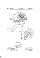
Still other objects and attendant advantages will be manifest from the detailed description of the attached drawings, whereof Fig. Lis a skeletonized partialfrear elevatio'n of a full fashioned stocking knitting machine conveniently embodying the stop control mechanism'of my invention, with certain portions broken out and others shown -in section to expose important `details.
"Fig, II is a fragmentary end elevation of the carrier rod stops modified for the purpose of my invention.
The knitting machine partly shown in the several illustrations is, generally spealn'ng, of standard construction in that it embodies a multiplicity of longitudinally extending yarn carrier rods 10. These yarn carrier rods are supported for endwise sliding movement by suitable brackets (not shown) afforded by the machine frame which is yldesignated 11, and receive movement by virtue of connection,
'through friction boxes, from the friction rod (not shown) of the machine, all in a wellknown manner. As usual, the machine is provided with narrowing heads at opposite ends, one such head being-shown-and comprehensively indicated by the numeral 12 in Figs. I and II. Each such narrowing head comprises among other parts, a lead screw 13 for thecarrier rod stop nut 14, said screw being rotatable in bearings 15 which are provided by brackets 17, 18 bolted to a horizontal su porting bar 19 of the machine frame.
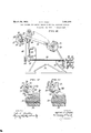
usual, the nut v14E is formed with spaced angularly projectingears 20, 21' (Fig. II) that supv port between them a transverse axis rod 22, whereon are lmounted for independent moveinepta series of gravity-influenced stop 1evers 23, in this case four, which are properly allocated toco-operate with certain of the yarn carrier rods 10, and fitted on their free ends with adjustable stop screws 24. By means of integrally formed handles 25, the stop levers 23am swingablemanually on the axis rod 22 into and out of active position relative to checo-ordinated carrier rods 10-fin a manner well understood.
Sli
As hereinbefore stated, the chief aim of my present invention is to control the yarn carrier sto levers 10 of a knitting machine such as just riely described, automatically. The mechanism which is provided for this purpose includes a shaft 26 having support in supplemental bearing arms 27, 28 bolted or otherwise fastened to the ears 20, 21 on the nut 14 of the narrowing head 12. On this shaft 26 are secured, with capacity for rotative adjustment by means of screws 29, a number of collars 30 to align with the stop levers 23. The heads of the screws 29 are adapted, when the shaft 26 is turned, to engage lugs 3l secured to the bosses of said stop levers, see Figs. IV, V and VI, more particularly. From these illustrations it will be noted that the lugs 31 are adjustably secured to the stop levers 23 by means of screws 32 which pass through longitudinal slots in the tails 31a .of A
` said lugs. In effect, the collars 30 constitute adjustable sections of a rotary drum element with circumferentially spaced radial projections-the screw heads 29-which are influential individually upon the stop levers 10' '.ing outward from the ear 21 of the nut 14.
Rigidly fastened to the gear 34 is a miter pinion 35 which in turn meshes with a miter pinion 36 on a positionally fixed shaft 37 that extends parallel with the lead screw 13 and has journal support in outwardly reaching bearing arms 38, 39 of the brackets 17, 18. To predetermine travel of the miter pinion 36 along the shaft 37 under influence ofthe nut 14, its hub is circumferentially grooved as at 40 in Fig. I for engagement by a forked arm 41 rigidly secured to the ear 21 of the nut 14. Incident to sliding after. the manner just explained. the pinion 36 is obliged to rotatey with the shaft 37 by virtue 'of a spline connection 42. For intermittently rotating the shaft 37 in order to effect successive actuation of the carrier rod stop levers 23 as more fully explained later, I secure adjacent the bearing 39. a lratchet wheel 43 which is arranged to be picked by a spring influenced pawl 44 on a lever 45 free to'swing on said shaft. This le` ver 45 is coordinated, through the medium of a downward link 46, to the longer extremity 47a of a bellcrank lever 47 with fulcrum attachment at 48 on a supplemental bearing ,bracket 49 secured to the longitudinal channel rail 50 at the back of the machine frame. .The
tudinally of the back of the machine where it is supported in bearings having capacity for vertical as well` as." horizontal adjustment relative to the machine frame 11, one of such Y 47, and, through the connections previously described in effecting picking of a'tooth 0f the ratchet wheel 43 on the shaft 37 at each actuatioln It is to be understood that the parts thus far described are duplicated in connection with the narrowing head at the opposite extremity of the machine.
Any suitable means may be employed for rotating the auxiliary shaft 54' intermittently to bring about the above described operation, but it is preferred to govern its movements from the measuring chain of the machine which is partly shown at 56 in Figs. I and III. To this end the chain 56 is fitted with a series of special lugs or buttons 57 for engaging a roller 58 on an arm 59 secured toone end of a shaft 60. This shaft 60 extends crosswise of the machine and is journalled in supplemental bearings 61, 62 bolted respectively to the longitudinal channel rail 50 at the back of the machine and the angle rail 63 at the front. At its opposite end, the shaft 60 has secured to it an arm 64 which is coupled, through the medium of an upward-` ly extending link 65, with the laterally extending arm 66a 'of a pawl guard 66 free to saving on the auxiliary cam shaft 54. The segmental portion 66() of the pawl guard 66 operates to control picking of a ratchet wheel 67 secured to the auxiliary cam shaft 54, by a pawl 68 which is pivoted to the end of another arm 69 free on said cam shaft along side the pawl guard 66, see Figs. I and III.
The pawl arm 69 is constantly vibrated byA virtue of connection to the rod 70 of an eccentric 71 mounted on the main shaft of the machine shown at 72 in Figs. I and III.
The operation of my invention is as follows: Each time that one of the special buttons 57 on the measuring chain 56 passes beneath the roller arm 59 (Fig. I), the transverse shaft 60 is slightly rotated and movement communicated, through the arm 64 and the link 65, to .the pawl guard 66. The sector 666 of the pawl guard 66 is consequently retracted to permit picking of one tooth of the ratchet wheel 67 by the pawl 68. Due
to the movenient thus induced in the auxiliary cam shaft 54, one of the rises 52al of .the groove 52 in the rotary cani 53 is brought into line with the roller-51 on the bell crank lever 47 and motion thereby imparted, to said bell crank lever for communication, through. the link 46to the arm 45 serving the pawl 44 which is coordinated with the vratchet cumstances, the shaft 37 is rotated through an angular extent corresponding to the pitch of the teeth of the ratchet -wheel 43; and this motion is transmitted, through the bevel Wheel 43 on the shaft 37: Under these ciry predetermined for the end stop levers 23 as Y gears 36, 35 and the spur gears 34, 33, to the shaft 26 on the yarn carrier stop nut 14 carrying the drum collars for actuating the swingable stop levers 23.
By suitably adjusting the drum collars 30 on the axis 26 to variously allocate the projecting heads of the screws 29 angularly and 'by correspondingly arranging the buttons' 57 on the measuring chain 56, any desired sequence or order of selection may obviously be required incident to interchange ofdierent yarn carriers during the knitting of the stockings on the machine in proper timed relation to other events in the cycle.
My automatic control mechanism is thus highly advantageous not/only in that it obviates mistakes common to substitution of one carrier rods and a series of independently\ pivoted end stops for the yarn carrier rods; of control mechanism for the end stops including a rotatable drum element having circumferentially spaced adjustable projections influential upon said end stops in selectively operating them, and means to intermittently rotate the drum element.
` 2. The combination in a iat knitting machine embodying a multiplicity ofy'sliding yarn carrier rods, and a series of independently pivoted Aend stops with adjustable lugs for the carrier rods; of control mechanism for the end stops including a rotatable drum element having spaced circumferential projections to cooperate with the adjustable lugs on said end stops in selectively swinging the latter and means for rotating vthe drum element. 3. The combination in a flat knitting machine embodying a multiplicity of sliding yarn carrier rods and a series of independently pivoted endstops; Qof control mechanism for ,the end stops comprising a `shaft supporting a rotatable drum element, said element including component sections capable of separate adjustment"on the supporting shaft and affording a series of circumferentially spaced projections for engaging the end stops aforesaid in selectively swinging n them, and means for rotating the shaft.
4. The combination in a flat knitting machine comprising ameasuring chain, a multiplicity of sliding yarn carrier rods, and individually-pivoted end stops for the carrier mods; of automatic control mechanism governed by the measuring chain for selectively swinging the end stops aforesaid into and out of action.
5. The combination in a flat knitting Vmachine with a multi licity of sliding yarn carrier rods, and independently pivoted individual end stops for the carrier rods; of automatic control mechanism, including a rotative element having circumferentially-spaced relatively-adjustable projections, governed by the measuring chain for selectively operating the end stopsaforesaid.
6. The combination in a liat knitting machine embodying a measuring chain, a multiplicity of sliding yarn carrier rods, and a series of independently pivoted end stops 30 for the yarn carrier rods; of control mechanism for 'the end stops including a rotata-V ble drum element having circumferentially spaced adjustable projections influential in selectively swinging said end stops into and out of action, and means governed by the measuring chain of the machine for rotating the drum element.
7. The combination in a flat knitting ma chine embodying a multiplicity of sliding yarn carrier rods, and narrowing mechanism comprising a screw operated nut fitted with a series of independently pivoted end stops for the yarn carrier rods; of control mecha- Y nism for the, end stops including a drum 'J5 element rotatably supported by the nut aforesaid and having circumferentially spaced adjustable projections influential in selectively swinging the end stops into and out of action, and means for rotating the drum element. 133 8. The combination in a fiat knitting mai i `chine embodying a measuring chain, a nultiplicity `of sliding yarn carrier rods, and narrowing mechanism comprising a screw op-- erated nut fitted with a series of independ- P35 ently pivoted end' stops for the yarn carrier rods; of control mechanism for the end stops including a drum element rotatably mounted on the nut and having circumferentially spaced adjustable projections influential in selectively swinging said end stops into and out of action, and means governed vby the measuring chain of thmnachine for rotating the drum element. 9. The combination in al flat knitting ma- H5 chine 7embodying -a multiplicity of sliding yarn carrier rods, and narrowingmechanism r comprising a screw operated nut fitted with t a ,series of independently pivoted end stops f cam shaft with av rotary cam thereon foi' actuating a pawl to pick the ratchet lWheel.
10.v The combination in a flat knittmg machine embodying'- a measuring chain, a multiplicity of sliding yarn carrier rods, andvnarrowing mechanism comprising a screw operated nut fitted with a series of independently pivoted end stopsi for the yarn carrier i rods; of mechanism to control the yarn carrier end stops including a drum element rotatably mounted on the nut aforesaid and having circumferentially spaced adjustable projections influential inI selectively swinglng the yarn carrier rod end stops into and out of action, a gear wheel on the drum element inr mesh with a gear slidable on a positionally'fixed shaft extending parallel to the screw for the nut aforesaid, a ratchet wheelA Ion the shaft, an auxiliary cam shaft with a rotary cam thereon for actuating a pawl tof pick` the ratchet wheel; and means governed by the measuring chain of the machine to impart intermittent rotary movement-to the auxiliary shaft. Y
11. The combination in a flat knitting machine embodying a measuring chain, a multiplicity of sliding yarn /carrier rods, and narrowing mechanism comprising a screw operated nut fitted with a series of independently pivoted end stops for the yarn* carrier rods; of mechanism to control the yarn Carrier end stops including a drum element rotatably mounted on the nut and having circumferentially spaced/adjustable projections iniuential in selectively swinging the.
yarn carrier rod end stopsfnto and out of action, a gear wheel on the drum element in mesh with a gear slidable on a positionally fixed shaft extending parallel to the screw for the nut aforesaid, a ratchet Wheel on the Y shaft, an auxiliary cam shaft with a rotary A cam thereon for actuating a pawl to pick the l En ratchet wheel, a ratchet wheel on said auxiliary shaft, another pawl constantly vibrated through an eccentric. connection with the main cam shaft of the machine, a pawl guard to control the action of the last mentioned pawl, and interposed means whereby said pawl guard is governed from the measuring chain. y
In testimony: whereof, I have hereunto signed my name at Philadelphia, Pennsylvani,"this 26th day of December, 1929.
- HAROLD'F. PAGET.
Priority Applications (1)
| Application Number | Priority Date | Filing Date | Title |
|---|---|---|---|
| US417430A US1851209A (en) | 1929-12-30 | 1929-12-30 | Yarn carrier stop control mechanism for flat knitting machines |
Applications Claiming Priority (1)
| Application Number | Priority Date | Filing Date | Title |
|---|---|---|---|
| US417430A US1851209A (en) | 1929-12-30 | 1929-12-30 | Yarn carrier stop control mechanism for flat knitting machines |
Publications (1)
| Publication Number | Publication Date |
|---|---|
| US1851209A true US1851209A (en) | 1932-03-29 |
Family
ID=23654008
Family Applications (1)
| Application Number | Title | Priority Date | Filing Date |
|---|---|---|---|
| US417430A Expired - Lifetime US1851209A (en) | 1929-12-30 | 1929-12-30 | Yarn carrier stop control mechanism for flat knitting machines |
Country Status (1)
| Country | Link |
|---|---|
| US (1) | US1851209A (en) |
-
1929
- 1929-12-30 US US417430A patent/US1851209A/en not_active Expired - Lifetime
Similar Documents
| Publication | Publication Date | Title |
|---|---|---|
| US2164118A (en) | Knitting machine | |
| US2330681A (en) | Machine and process for knitting hosiery blanks | |
| US2185963A (en) | Tension-regulating device for the draw-off mechanism of full-fashioned knitting machines | |
| US1851209A (en) | Yarn carrier stop control mechanism for flat knitting machines | |
| US1191592A (en) | Bunch-forming device for cigar-machines. | |
| US2084732A (en) | Flat knitting machine | |
| US2186023A (en) | Knitting machine | |
| US1505028A (en) | Banding-machine attachment | |
| US2667053A (en) | Mechanism for double sole trimming | |
| US1850520A (en) | Friction box control mechanism for flat knitting machines | |
| US2221713A (en) | Knitting machine | |
| US1809063A (en) | Pattern mechanism for straight knitting machines | |
| US2175989A (en) | Loop length regulating mechanism for straight knitting machines | |
| GB385946A (en) | Improvements in or relating to tobacco-feeding machines | |
| US1194584A (en) | Pattern mechanism eos knitting-machines | |
| US2104232A (en) | Knitting machine | |
| US2002116A (en) | Knitting machinery | |
| US1523915A (en) | Take-up for knitting machines | |
| US2426010A (en) | Wrap spindle | |
| US962291A (en) | Circular-fashioning knitting-machine. | |
| US1127769A (en) | Circular-knitting machine. | |
| US1881373A (en) | Yarn carrier stop block control mechanism for flat knitting machines | |
| US1826660A (en) | Loop regulating mechanism for full fashioned hosiery knitting machines | |
| US1622345A (en) | Pattern mechanism for dobbies | |
| US2239810A (en) | Device for locking the thread carrier bars of flat knitting machines |