US1851202A - Device for preventing vessels from bursting - Google Patents
Device for preventing vessels from bursting Download PDFInfo
- Publication number
- US1851202A US1851202A US411926A US41192629A US1851202A US 1851202 A US1851202 A US 1851202A US 411926 A US411926 A US 411926A US 41192629 A US41192629 A US 41192629A US 1851202 A US1851202 A US 1851202A
- Authority
- US
- United States
- Prior art keywords
- valve
- liquid
- movable
- seat
- freezing
- Prior art date
- Legal status (The legal status is an assumption and is not a legal conclusion. Google has not performed a legal analysis and makes no representation as to the accuracy of the status listed.)
- Expired - Lifetime
Links
- 230000009172 bursting Effects 0.000 title description 3
- 239000007788 liquid Substances 0.000 description 18
- 230000008014 freezing Effects 0.000 description 10
- 238000007710 freezing Methods 0.000 description 10
- 238000007789 sealing Methods 0.000 description 8
- 230000001050 lubricating effect Effects 0.000 description 6
- 239000004519 grease Substances 0.000 description 5
- 239000000463 material Substances 0.000 description 5
- 238000010276 construction Methods 0.000 description 3
- 238000005461 lubrication Methods 0.000 description 2
- XLYOFNOQVPJJNP-UHFFFAOYSA-N water Substances O XLYOFNOQVPJJNP-UHFFFAOYSA-N 0.000 description 2
- 101100441413 Caenorhabditis elegans cup-15 gene Proteins 0.000 description 1
- 102000012152 Securin Human genes 0.000 description 1
- 108010061477 Securin Proteins 0.000 description 1
- 230000006835 compression Effects 0.000 description 1
- 238000007906 compression Methods 0.000 description 1
- 230000006866 deterioration Effects 0.000 description 1
- 239000012530 fluid Substances 0.000 description 1
- KRTSDMXIXPKRQR-AATRIKPKSA-N monocrotophos Chemical compound CNC(=O)\C=C(/C)OP(=O)(OC)OC KRTSDMXIXPKRQR-AATRIKPKSA-N 0.000 description 1
- 230000003647 oxidation Effects 0.000 description 1
- 238000007254 oxidation reaction Methods 0.000 description 1
- YNWDKZIIWCEDEE-UHFFFAOYSA-N pantoprazole sodium Chemical class [Na+].COC1=CC=NC(CS(=O)C=2[N-]C3=CC=C(OC(F)F)C=C3N=2)=C1OC YNWDKZIIWCEDEE-UHFFFAOYSA-N 0.000 description 1
- 235000002020 sage Nutrition 0.000 description 1
- 239000007787 solid Substances 0.000 description 1
Images
Classifications
-
- F—MECHANICAL ENGINEERING; LIGHTING; HEATING; WEAPONS; BLASTING
- F16—ENGINEERING ELEMENTS AND UNITS; GENERAL MEASURES FOR PRODUCING AND MAINTAINING EFFECTIVE FUNCTIONING OF MACHINES OR INSTALLATIONS; THERMAL INSULATION IN GENERAL
- F16K—VALVES; TAPS; COCKS; ACTUATING-FLOATS; DEVICES FOR VENTING OR AERATING
- F16K17/00—Safety valves; Equalising valves, e.g. pressure relief valves
- F16K17/36—Safety valves; Equalising valves, e.g. pressure relief valves actuated in consequence of extraneous circumstances, e.g. shock, change of position
- F16K17/38—Safety valves; Equalising valves, e.g. pressure relief valves actuated in consequence of extraneous circumstances, e.g. shock, change of position of excessive temperature
-
- F—MECHANICAL ENGINEERING; LIGHTING; HEATING; WEAPONS; BLASTING
- F16—ENGINEERING ELEMENTS AND UNITS; GENERAL MEASURES FOR PRODUCING AND MAINTAINING EFFECTIVE FUNCTIONING OF MACHINES OR INSTALLATIONS; THERMAL INSULATION IN GENERAL
- F16K—VALVES; TAPS; COCKS; ACTUATING-FLOATS; DEVICES FOR VENTING OR AERATING
- F16K17/00—Safety valves; Equalising valves, e.g. pressure relief valves
- F16K17/003—Safety valves; Equalising valves, e.g. pressure relief valves reacting to pressure and temperature
-
- Y—GENERAL TAGGING OF NEW TECHNOLOGICAL DEVELOPMENTS; GENERAL TAGGING OF CROSS-SECTIONAL TECHNOLOGIES SPANNING OVER SEVERAL SECTIONS OF THE IPC; TECHNICAL SUBJECTS COVERED BY FORMER USPC CROSS-REFERENCE ART COLLECTIONS [XRACs] AND DIGESTS
- Y10—TECHNICAL SUBJECTS COVERED BY FORMER USPC
- Y10T—TECHNICAL SUBJECTS COVERED BY FORMER US CLASSIFICATION
- Y10T137/00—Fluid handling
- Y10T137/1189—Freeze condition responsive safety systems
- Y10T137/1353—Low temperature responsive drains
-
- Y—GENERAL TAGGING OF NEW TECHNOLOGICAL DEVELOPMENTS; GENERAL TAGGING OF CROSS-SECTIONAL TECHNOLOGIES SPANNING OVER SEVERAL SECTIONS OF THE IPC; TECHNICAL SUBJECTS COVERED BY FORMER USPC CROSS-REFERENCE ART COLLECTIONS [XRACs] AND DIGESTS
- Y10—TECHNICAL SUBJECTS COVERED BY FORMER USPC
- Y10T—TECHNICAL SUBJECTS COVERED BY FORMER US CLASSIFICATION
- Y10T137/00—Fluid handling
- Y10T137/4238—With cleaner, lubrication added to fluid or liquid sealing at valve interface
- Y10T137/4358—Liquid supplied at valve interface
- Y10T137/4372—Line pressure feed
-
- Y—GENERAL TAGGING OF NEW TECHNOLOGICAL DEVELOPMENTS; GENERAL TAGGING OF CROSS-SECTIONAL TECHNOLOGIES SPANNING OVER SEVERAL SECTIONS OF THE IPC; TECHNICAL SUBJECTS COVERED BY FORMER USPC CROSS-REFERENCE ART COLLECTIONS [XRACs] AND DIGESTS
- Y10—TECHNICAL SUBJECTS COVERED BY FORMER USPC
- Y10T—TECHNICAL SUBJECTS COVERED BY FORMER US CLASSIFICATION
- Y10T137/00—Fluid handling
- Y10T137/7722—Line condition change responsive valves
- Y10T137/7837—Direct response valves [i.e., check valve type]
- Y10T137/7879—Resilient material valve
-
- Y—GENERAL TAGGING OF NEW TECHNOLOGICAL DEVELOPMENTS; GENERAL TAGGING OF CROSS-SECTIONAL TECHNOLOGIES SPANNING OVER SEVERAL SECTIONS OF THE IPC; TECHNICAL SUBJECTS COVERED BY FORMER USPC CROSS-REFERENCE ART COLLECTIONS [XRACs] AND DIGESTS
- Y10—TECHNICAL SUBJECTS COVERED BY FORMER USPC
- Y10T—TECHNICAL SUBJECTS COVERED BY FORMER US CLASSIFICATION
- Y10T137/00—Fluid handling
- Y10T137/7722—Line condition change responsive valves
- Y10T137/7837—Direct response valves [i.e., check valve type]
- Y10T137/7904—Reciprocating valves
- Y10T137/7922—Spring biased
- Y10T137/7929—Spring coaxial with valve
- Y10T137/7932—Valve stem extends through fixed spring abutment
Definitions
- y i f klblef f l ilt erohject :of the invention is to ⁇ prov A,djacentfthe. inner yend of this housing V ⁇ vide a device of the ,class'described which there are provided thesemicircular:ports?
- a further ob'ectfof the invention is to pro-f A p *n Engager;lole in kthen-valve seat member lis Y vide a simple means for the lubrication of the y a valve 9 of truncated cone-shape adapted to f 25 movable parts of; the device as well as to ex snugly engage its seat.
- the valve 9 is provid- 75 clude the freezing liquid fromrr Contact witlied with the outwardly extending cylindrical Y those portions of the device that might he portion l0 forengagement with pistonmeans ienderedinoperablehysaid frozen liquid.
- Y -ll constituting a portionfof the means for Afm-ther Objecgofmyinvention is to pro-4 lubrication by the supply of grease inthe [which isjof simple construction, hasfew nninicating with the'cylindrical portion lO'is ipartsand' is not liable tto easily get out of a passageway l2 leading ⁇ toy the .passagefl2a order.V K v and thence to the 'circular reduced portion 13 @there objects andadvantages of the in- Yin tlleloody of thevvalve.y lThejpiston llis fication and the novel features will' be parpassagek 14 communicating Withfthe grease ⁇ ticula-rly pointed out in the appended claims Cup means 'l'monnted rOntheendyof the @K+ My invention 'is illustrated" in the 'accomtension I6 of thepiston. For forcing the ⁇ pis
- This device as has been previously stated is designed to be mounted upon a container for liquids subjected to freezingtemperatures and should be so mounted on said container as to present the inner portion of the truncated cone member in that place in said container in which the Water freezes last. This positionis ordinarily the center of said container. As the liquid expands, due to the freezing thereof, theyalve member 9 is forced outwardly upon its seat lpermitting the flow of liquid between the truncated cone portion and said seat to the semi-circular-shaped ports 7 which constitutetheexitfor said-liquid.
- the pressure of the ⁇ spring 17y serves to insure a ready supply of "said"grease.' This 'greasefprevents 'seepage yof, Waterby capillary'attraction between'y t e wallsiof the 'members-l and 9 when the-'valve "is in closed position. It also serves to lubricate the Valve with relation to its seat for ⁇ easyl operationthereof which is especially ,effective in my "device, since ice will not adhere to the parts so lubricated. lt-is ⁇ therefore easy to be seen ⁇ that a de vice is provided which will accommodatedilypermit theliquid to flowfrom the container when l thesame expands, due to freezing, thereby Apreventing the container or vessel from ursting.
- This annulus 22 Vhas ports 25 ofany suitablev construction andwhich may yformedy inan enlargediportion of the annulus as in the preceding form.
- the movable member26 of the valve is of substantially 6o'similarcon'struction to that of the preceding form except that it has a reduced portion27, projecting portions 28, and a solid stemr26 ⁇ surrounded by spring'26b, which engages-cap 24 and shoulder 26cvto normally urgevalve member. 26 to closedy position.
- Surrounding -cooperates for securin the portions of the movable member 26, which engage the walls of the valve seat member is a jacket composed of any suitable material to which ice will not adhere, such as rubber.
- the neck 31 of this jacket is made 0f a 70 smaller circumference than the reduced p0rtion 27 of the movable valve 26 with which it the said jacket in close, fixed relation wlth said reduced portion. Since ice will not adhere to this material 'and' therebytend to freeze the same to the valve seat, the sensitiveness of the valve is greatly increased overy those forms of freeze valves using Vmaterial in the valve engaging surfaces' to which iceadheres.
- Afvalve responsive totheV pressure exerted by a freezing 'liquid comprising a valve seat member, a movable'valve member engag-y 100 f ing the valve seat, and means for lubricating Lthe engaging walls of said members andfor sealing the space between said wallsywhereby the seepage ofliquid past said valve and consequentfreezing between the valve and ⁇ seat member isv prevented whenY the Valveis seated.
- a sealingand lubricatingv means'for the engagingWalls of a movable member 'anda stationary member ina valve comprisA no in'g a reduced portion onv saidlmovab'le member, a passagewayin vsaid movable member 'commumcating with said reduced portion,
- a sealing ⁇ and lubricating means ⁇ for. the engaging Walls of amo-Vahlemember and a stationary member in a valve, comprising a Vreducedportion'on said movable member, a passageway in said/movabley member communicating with said reduced portion, resilient pressure meansV for forcing sealing and lubricating material through said passagewayand into said reducedportion, saidk means comprising Va cylinder formed onv the top of Vsaid movable means l and communicating with saidpassageway,-
- said forcing meansk comprising apassageway extending through ing vessel, a reciprocableV valvev mounted said piston and communicatingwith said cylinder and provided With a source of supply of the sealing and lubricating material for the purpose described.
- a pressure valve for the release of liquid from a liquid containing( vessel sub? jected yto freezing temperatures comprising..
- a casing having anrelongated valve seat member detachably mounted upon one end thereof, external screwy threads formed at the -junctionof said casing and vvalve, seat member for mounting in the liquid contain- Within said casing kand adapted to seat in said valvefseat member, sprmg means for holding said valve in seated engagement, ⁇ j
- a pressure valve for release ofliquid from a liquid containing vessel ysubjected to freezing temperatures comprising ⁇ a casingk having an elongated valve seat member upon p one end thereof, externalfscrew vthreads upon said casingforV mounting in the ⁇ liquidconV ⁇ taining vessel, said threads being Vformed at a Vpointupon said casing to dispose the major portion of said valve seat member Within said vessel, a reciprocable valve mounted Within said casing and adaptedto seat in said valve seat member, spring means for holding said valve in seated engagement, and said casing having l ports ⁇ extendingy outward from said seat member, whereby free movement of liquid through said valve Will be permitted.
Landscapes
- Engineering & Computer Science (AREA)
- General Engineering & Computer Science (AREA)
- Mechanical Engineering (AREA)
- Safety Valves (AREA)
Description
March 29, 1932.
V.MERRWT DEVICE FOR PREVENTING VESSELS FROM BURSTING.
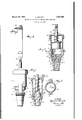
Filed bec. 5;- 192s lNvENToR grnan rrz YMF@ y ATTORNEY eoledengines, etc. ,rand it consists in the c om-A In carrying out rn'y invention infaccord-w55l iprov'e'mentover my invention disclosed in a a reducedfportionQ 1withthreads 3 thereon eo p il ilyV bemounted onor incorporated in a -con- 6 adapted to engage thethreads in the ywall '65 l if 30 'vide la device joffthe character described manner to bel described hereinafter. Com-v 8o 7;-35 "vention will appear in the following speci?y pfOVCled With 31011gti1flinally extending 8x5k plication, in which: v kspring 1T is provided Vsurrounding the exteni 9G,
355455-11157 jdevice suhstantially'on the line 242 of'. sion lli-of the piston member 1l is slidably'f95 Patented Mar.i29f,` 1932 Y j i A c UNHTED STATES Arefllfiffii*if @FE-*ice f l l Y 'i y y ,l MERRITT, or MONTGOMERY, tanning i .A l *Y i, nnvion FOR rnnvnnrindvnssnns'nnoivrYBURSTING i ppliafion filed December 5,11929. serial No. iiiza i Y inveiltion'relates to 'improvements in ingr my device mounted'foroperation onthey "fdevicesfor' thepurpose of-preventing' the' Vradiator of an automobile, and i Y "burstingfby freezing of inetalpiping or other ignre is a sectionalview of a modified Y containers, such asl steamf fittings," water form of my device. l i' f vhinations," construction and arrangement of ance with they form of l'Fig'uresl to 4 inclus,-
pafts as vvill he' hereinafter more fully desive, I make use of an? extended valvev seat 'Y scribed 'and claimed, i ".memloer lof trnncated'cone shaped forni. The'present invention is designed as anfini provided atthe outer extremity thereof vwith copendi'ng application Serial No. 348,856', for engagement with vthe threads 4 upon the rfiled MarchV 21,1929; harrelhonsing portion 5. y Y Y i )loject ofthe invention is to provide a Tliis'harrel housing is provided attheflower f device of the class Set'forthwhich can readextremity thereof 4with tlieexternal threads tainer or piping containingliqnid subject to of the container in'whichthe device is oper- 'freezin temperature. y i f klblef f l ilt erohject :of the invention is to `prov A,djacentfthe. inner yend of this housing V`vide a device of the ,class'described which there are provided thesemicircular:ports? 20 `will not be'rendered inoperable byclogging separatedhy the supporting portions of said 7C ofthe parts Vthereof: withl ice jfornfied'v from housing, indicatedat y8, forapnrpose presentthe free'zinglliquid, Y 'y f ly to bedescjriloed. l
A further ob'ectfof the invention is to pro-f A p *n Engager;lole in kthen-valve seat member lis Y vide a simple means for the lubrication of the y a valve 9 of truncated cone-shape adapted to f 25 movable parts of; the device as well as to ex snugly engage its seat. The valve 9 is provid- 75 clude the freezing liquid fromrr Contact witlied with the outwardly extending cylindrical Y those portions of the device that might he portion l0 forengagement with pistonmeans ienderedinoperablehysaid frozen liquid. Y -ll constituting a portionfof the means for Afm-ther Objecgofmyinvention is to pro-4 lubrication by the supply of grease inthe [which isjof simple construction, hasfew nninicating with the'cylindrical portion lO'is ipartsand' is not liable tto easily get out of a passageway l2 leading` toy the .passagefl2a order.V K v and thence to the 'circular reduced portion 13 @there objects andadvantages of the in- Yin tlleloody of thevvalve.y lThejpiston llis fication and the novel features will' be parpassagek 14 communicating Withfthe grease` ticula-rly pointed out in the appended claims Cup means 'l'monnted rOntheendyof the @K+ My invention 'is illustrated" in the 'accomtension I6 of thepiston. For forcing the `pispanying drawings forming a part ofthis apton into engagementwith the cylinder 10, the
, I' Figure'l is an elevational View vof the in# sionofsaidpiston and operably engaging the 'y vention, `showingmeai'is for inounting the `upper portion` of said piston and the innerside f same upon a yliquid container; yof the cap member 1S threadedlymounted on; i Figure 2 is a sectional elevational'view of therbarrelhousing and in which the exten- VUFigure 1,/vvitlipartsthereofheingshowninengagedH f i YVf'elev'ation; Q y f Q l f Figure 4fshows-my1device nfiountedy hy,v Figure-3"isa-transverse sectional viewofmeansiof its -mountingthreadsgr in therai* my devi'ceon'the line r-*Sof Figure; f *diator of jan automobile. 'i If positioned at 150 yFigure 4fisf9any end elevational view, show? Athe-c'renter ofthe lastplace to freeze inV said'i radiator, the valve will operate to release the excess liquid, which will be forced through said valve and from the radiator due to the pressure exerted bythe freezing liquid on the liquid in engagement with my device.
From the foregoing description of the various parts of the device the operation thereof may be readily understood. This device as has been previously stated is designed to be mounted upon a container for liquids subjected to freezingtemperatures and should be so mounted on said container as to present the inner portion of the truncated cone member in that place in said container in which the Water freezes last. This positionis ordinarily the center of said container. As the liquid expands, due to the freezing thereof, theyalve member 9 is forced outwardly upon its seat lpermitting the flow of liquid between the truncated cone portion and said seat to the semi-circular-shaped ports 7 which constitutetheexitfor said-liquid. 'The-reduced portion 13 'isprovide'd with'grease from the grease cup 15 by means 'of thepassageway inthe piston' member 11, grease compression o chamber provided in ycylind'erliO and,pasv freezing. f
Sage'ways 12 and 12a. The pressure of the `spring 17y serves to insure a ready supply of "said"grease.' This 'greasefprevents 'seepage yof, Waterby capillary'attraction between'y t e wallsiof the 'members-l and 9 when the-'valve "is in closed position. It also serves to lubricate the Valve with relation to its seat for `easyl operationthereof which is especially ,effective in my "device, since ice will not adhere to the parts so lubricated. lt-is` therefore easy to be seen` that a de vice is provided which will vreadilypermit theliquid to flowfrom the container when l thesame expands, due to freezing, thereby Apreventing the container or vessel from ursting.
y y lIn that formof the device `shown in Figure '5 theV stationary valve'seatlmember 20 threadedly engages ra mounting' collar 21 asin the '.precedingform. This mounting collar 21, however, is of mu'ch'snnpl'er form than the similar supporting 4means of the preceding form. It consists ofa 'simple annulus having the threads 22 at one end thereof for engavement'with the wallsJ of the aperture kin t e chamber in'which it is used andthe threads Ak123 on lthepopp'osite end thereof for engagevfment with a capv member 24 for enclosing the end thereof. This annulus 22 Vhas ports 25 ofany suitablev construction andwhich may yformedy inan enlargediportion of the annulus as in the preceding form. The movable member26 of the valve is of substantially 6o'similarcon'struction to that of the preceding form except that it has a reduced portion27, projecting portions 28, and a solid stemr26 `surrounded by spring'26b, which engages-cap 24 and shoulder 26cvto normally urgevalve member. 26 to closedy position. Surrounding -cooperates for securin the portions of the movable member 26, which engage the walls of the valve seat member is a jacket composed of any suitable material to which ice will not adhere, such as rubber. The neck 31 of this jacket is made 0f a 70 smaller circumference than the reduced p0rtion 27 of the movable valve 26 with which it the said jacket in close, fixed relation wlth said reduced portion. Since ice will not adhere to this material 'and' therebytend to freeze the same to the valve seat, the sensitiveness of the valve is greatly increased overy those forms of freeze valves using Vmaterial in the valve engaging surfaces' to which iceadheres.
The o eration of this form of the device is substantially'similar to that of the preceding form. The pressure exerted on the liquid adn jacent the valve bythe freezing of the liquid movable member and the valve seat 20 and the Iemission of said fluid from ports 25, thuisV 90 preventing the vesselr from bursting due to It is obvious that the jackets 30 are removable, thereby making it vvery easy to replace the sameupoii deterioration' thereof, due to 95 oxidation'orr decay.Y
I" claim: n
1. Afvalve responsive totheV pressure exerted bya freezing 'liquid comprising a valve seat member, a movable'valve member engag-y 100 f ing the valve seat, and means for lubricating Lthe engaging walls of said members andfor sealing the space between said wallsywhereby the seepage ofliquid past said valve and consequentfreezing between the valve and `seat member isv prevented whenY the Valveis seated. K
2. A sealingand lubricatingv means'for the engagingWalls of a movable member 'anda stationary member ina valve, comprisA no in'g a reduced portion onv saidlmovab'le member, a passagewayin vsaid movable member 'commumcating with said reduced portion,
and resilient means for forcing sealing and lubricatingmaterial through said passagefu way, and into said reduced portion, for the purpose described. f
3. A sealing and lubricating means for the engaging 'walls of a movable membery and a stationary member `in alvalve, com-,.120 prising a reduced portion on said movable member, a passagewayy in said movable member communicatmg with said reduced` ortion, and resilienty pressure means for orcing sealing and lubricatingmaterial througlelgg; said passageway, and into said reduced portion, said meansy comprising y.a cylinder formed on the top kof said movable'means, and communicating with said passageway,
Wandy a piston Acooperating with said cylinder" 130 upon the operation of'said movable means. p
4. A sealing `and lubricating means `for. the engaging Walls of amo-Vahlemember and a stationary member in a valve, comprising a Vreducedportion'on said movable member, a passageway in said/movabley member communicating with said reduced portion, resilient pressure meansV for forcing sealing and lubricating material through said passagewayand into said reducedportion, saidk means comprising Va cylinder formed onv the top of Vsaid movable means l and communicating with saidpassageway,-
and a piston cooperating with said cylinder` i upon the operation of said movable means,V
and means for feeding the sealing .and lubricating material Ato said forcing meansk comprising apassageway extending through ing vessel, a reciprocableV valvev mounted said piston and communicatingwith said cylinder and provided With a source of supply of the sealing and lubricating material for the purpose described. o K
5. A pressure valve for the release of liquid from a liquid containing( vessel sub? jected yto freezing temperatures, comprising..
a casing having anrelongated valve seat member detachably mounted upon one end thereof, external screwy threads formed at the -junctionof said casing and vvalve, seat member for mounting in the liquid contain- Within said casing kand adapted to seat in said valvefseat member, sprmg means for holding said valve in seated engagement,` j
and said casing'having ports extending Voutwardly from said valve seat member, Whereby free movement of liquid through said valve will be permitted.
6. A pressure valve for release ofliquid from a liquid containing vessel ysubjected to freezing temperatures, comprising` a casingk having an elongated valve seat member upon p one end thereof, externalfscrew vthreads upon said casingforV mounting in the` liquidconV` taining vessel, said threads being Vformed at a Vpointupon said casing to dispose the major portion of said valve seat member Within said vessel, a reciprocable valve mounted Within said casing and adaptedto seat in said valve seat member, spring means for holding said valve in seated engagement, and said casing having l ports` extendingy outward from said seat member, whereby free movement of liquid through said valve Will be permitted.
VERNON MERRITT.
Priority Applications (1)
| Application Number | Priority Date | Filing Date | Title |
|---|---|---|---|
| US411926A US1851202A (en) | 1929-12-05 | 1929-12-05 | Device for preventing vessels from bursting |
Applications Claiming Priority (1)
| Application Number | Priority Date | Filing Date | Title |
|---|---|---|---|
| US411926A US1851202A (en) | 1929-12-05 | 1929-12-05 | Device for preventing vessels from bursting |
Publications (1)
| Publication Number | Publication Date |
|---|---|
| US1851202A true US1851202A (en) | 1932-03-29 |
Family
ID=23630832
Family Applications (1)
| Application Number | Title | Priority Date | Filing Date |
|---|---|---|---|
| US411926A Expired - Lifetime US1851202A (en) | 1929-12-05 | 1929-12-05 | Device for preventing vessels from bursting |
Country Status (1)
| Country | Link |
|---|---|
| US (1) | US1851202A (en) |
-
1929
- 1929-12-05 US US411926A patent/US1851202A/en not_active Expired - Lifetime
Similar Documents
| Publication | Publication Date | Title |
|---|---|---|
| US4066090A (en) | Water cock with non-freezing valve | |
| US2206356A (en) | Check valve | |
| US2263840A (en) | Rupturable disk mounting and indicator therefor | |
| US3850189A (en) | Safety valve having sealed reset means | |
| US3058718A (en) | Valve and sealing means therefor | |
| US2768806A (en) | Fluid control valves | |
| US3386700A (en) | Pressure seal bib | |
| US2353191A (en) | Automatic shutoff valve | |
| US1851202A (en) | Device for preventing vessels from bursting | |
| BRPI0704239B1 (en) | pressure compensated underwater chemical injection gate valve | |
| US3877476A (en) | Heat actuated valve | |
| US1926413A (en) | Choker | |
| US1960335A (en) | Check valve | |
| US2040776A (en) | Relief valve | |
| US6178930B1 (en) | Safety cap, particularly for cooling liquid circuits of i.c. engines for motorvehicles | |
| US2942617A (en) | Slip check valve | |
| US2599274A (en) | Rotary plug valve | |
| US3119408A (en) | Removable head and seat valve unit | |
| US2216150A (en) | Lubricated valve | |
| US2047120A (en) | Flush valve | |
| US1717573A (en) | Cap valve for gasoline tanks and batteries | |
| US1970131A (en) | Relief valve | |
| JP2530076Y2 (en) | Emergency shut-off valve | |
| US2530744A (en) | Line pressure lubricated plug valve | |
| US2410480A (en) | Lubricant fitting |