US1851186A - Sand and gravel cleaner - Google Patents
Sand and gravel cleaner Download PDFInfo
- Publication number
- US1851186A US1851186A US318200A US31820028A US1851186A US 1851186 A US1851186 A US 1851186A US 318200 A US318200 A US 318200A US 31820028 A US31820028 A US 31820028A US 1851186 A US1851186 A US 1851186A
- Authority
- US
- United States
- Prior art keywords
- screen
- tank
- gravel
- shaft
- shale
- Prior art date
- Legal status (The legal status is an assumption and is not a legal conclusion. Google has not performed a legal analysis and makes no representation as to the accuracy of the status listed.)
- Expired - Lifetime
Links
- 239000004576 sand Substances 0.000 title 1
- XLYOFNOQVPJJNP-UHFFFAOYSA-N water Substances O XLYOFNOQVPJJNP-UHFFFAOYSA-N 0.000 description 7
- 239000000725 suspension Substances 0.000 description 6
- 239000007788 liquid Substances 0.000 description 5
- 230000033001 locomotion Effects 0.000 description 5
- 239000000463 material Substances 0.000 description 5
- 239000000203 mixture Substances 0.000 description 4
- 230000008933 bodily movement Effects 0.000 description 3
- RYGMFSIKBFXOCR-UHFFFAOYSA-N Copper Chemical compound [Cu] RYGMFSIKBFXOCR-UHFFFAOYSA-N 0.000 description 1
- 238000010276 construction Methods 0.000 description 1
- PSGAAPLEWMOORI-PEINSRQWSA-N medroxyprogesterone acetate Chemical compound C([C@@]12C)CC(=O)C=C1[C@@H](C)C[C@@H]1[C@@H]2CC[C@]2(C)[C@@](OC(C)=O)(C(C)=O)CC[C@H]21 PSGAAPLEWMOORI-PEINSRQWSA-N 0.000 description 1
- 239000002184 metal Substances 0.000 description 1
- 239000006187 pill Substances 0.000 description 1
Images
Classifications
-
- B—PERFORMING OPERATIONS; TRANSPORTING
- B03—SEPARATION OF SOLID MATERIALS USING LIQUIDS OR USING PNEUMATIC TABLES OR JIGS; MAGNETIC OR ELECTROSTATIC SEPARATION OF SOLID MATERIALS FROM SOLID MATERIALS OR FLUIDS; SEPARATION BY HIGH-VOLTAGE ELECTRIC FIELDS
- B03B—SEPARATING SOLID MATERIALS USING LIQUIDS OR USING PNEUMATIC TABLES OR JIGS
- B03B5/00—Washing granular, powdered or lumpy materials; Wet separating
- B03B5/02—Washing granular, powdered or lumpy materials; Wet separating using shaken, pulsated or stirred beds as the principal means of separation
- B03B5/10—Washing granular, powdered or lumpy materials; Wet separating using shaken, pulsated or stirred beds as the principal means of separation on jigs
- B03B5/12—Washing granular, powdered or lumpy materials; Wet separating using shaken, pulsated or stirred beds as the principal means of separation on jigs using pulses generated mechanically in fluid
- B03B5/18—Moving-sieve jigs
Definitions
- a shaft 15 is supported for rotails 01" construotion' hereinafterl described tation on-the'side's of the tank 1', theshaft 515 and olaimed, it being understood that, Within being disposecl "near tofthe bottom of-the lfi i'the scopeiof What-is claimed, chan'gesin-the tank; 7
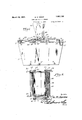
- Figurel shows in side elevation a device ,is permissible to substitute sprocket-Wheels r constructed in accordance with the invention, end-sprocket chains; this being a detail with parts beingfbroken away; i j I in-the skill of any meohanic'and calling for Figure 2 is a top f-plan of the removable no specific illustrationi
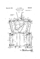
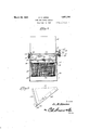
- belt confr'ame which carries'theseparator; 1 nection; therefore, is to be eonstruedto ins Figurefi is a vertical longitudinal-section; elude a chainand sprocket drive it the build- Figuret is'atopplan-wherein the separator or prefers to resort to that construction, on has been removed; 1 one end of the shaft 1A there is'a pulley 19.
- Figure'5 is a vertieal transversesection; On the frame '12 , a shaft 20 isfsupported J J FigureG is a detailshowing apart- 0 the for rotation; Af shaft-21 is supported for r0 7 f p at r V *5; tation'ti n the sides of the tank l and is dis- In oarryi'ngzout the inventionethere is proposed near the'bottom'of the tank.
- Pulleys vided a'liquidgcontainingtank 1'5 openatthe- '22 are mounted on the shafts- 21 and 20. top.
- Ahopper-2 extends across the tankl About the pulleys 22are engaged conveyor "frornside to side.
- the numeral 36 designates a pair of bars that form part of a screen support.
- Lower side plates 37 are secured at 38 to the bars 36.
- the upper edges of the lower side plates 37 overlap the lower edges of the upper side plates 30, as indicated at 39 in Figure 3 of the drawings.
- the bars 36 are connected by
- the screen 40 is heldat a substantially longitudinal inclination, less than the critical angle, that is, at the angle at which the material will move longitudinally of the screen, due to the weight of thematerial.
- the upper ends of the bars 36 swing for adjustment on pivot elements 41 that are mounted in the overlapped parts 39 of the side plates 30 and 37.
- the numeral 42 designates, generally, a suspension frame including side pieces 43,
- a top rod 44 terminating in studs 45 adapted to be mounted, for adjustment, in any of the openings 31 that are formed in the side plates 30.
- Nuts 46 are threaded on the studs 45 and engage the side plates 30 to hold the studs in place in the side plates.
- the side pieces 43 of the suspension rame 42 have inwardly extended arms 47 "( Figure 5) connected by a turnbuckle 48.
- the lower ends of the side pieces. 43 of the suspension frame 42 are pivotally mounted at 45 on the bars 36 thatcarry the screen 40.
- Clamping bolts 50 are mounted in the side plates 30 and are adjustable in arcuate slots 51 which are formed in the lower sideplates angle of the screen or bottom-40 by engaging thestuds 45 of the suspension frame '42 in the openings 31 of Figure 3, in a way which will be described hereinafter. It will be noted that the screen 40 has an unobstructed surface,
- Straps 52 are carried by the sidebars 60,
- eccentrics 53 turn within the straps
- the eccentrics 53 are mounted on shafts 54 and 55 that are journaled for rotation on the sills 29.
- belt 58 connects the pulley 56 with the pulley 19 on the shaft 14 of Figure 4.
- a belt 59 connects the pulley 57 with thepulley 25 on the shaft 20 of Figure 4.
- the belt 58 is a crossed belt.
- a hopper 61 is supported at 62 on the sills 29.
- the hopper 61 has a side outlet '63, and bearing brackets 64 are carried by the ho per.
- brackets 64 In the brackets 64 is journaled a she t 65,
- shafts 54 and 55 carry pulleys 70 engaged by a belt 71.
- the numeral 72 marks a drive pu'lley'on the shaft 55.
- the machine is handling gravel mixed with a lighter material, such as 1 shale, and that it is desired to get rid of the shale.
- the mixture of gravel and shale is cast into the hopper 61.
- the rotary feeder 66-65 carries the mixture of gravel and shale out of the outlet 63 of the hopper 61, and the mixture of gravel and shale drops into the rotary screen separator assembly, which, for
- tank 1 is filled with water, and the screen se arator 8 moves in the water in the tank.
- the screenseparator moves upwardly the mixture of shale and gravel carried upwardly in the water.
- the gravel is somewhat heavier than the shale and finds its way back on the screen 40 more quickly than does the shale.
- the heavy gravel gets back on the screen 40 as the screen is moving in the direction of the arrow A in Figure 3, and by the time that the lighter shale settles down ward on the screen 40, the screen is moving in the direction of the arrow B in Figure 3. The result is that the gravel tends to move down the screen 40 into the compartment 5,
- the screen 40 has a full orbital bodily movement in a vertical plane longitudinall of the screen, and means is provided for hol ing the screen wholly below the liquid surface at all stages of movement.
- the conveyors 17-18 take the gravel upwardly in thecompartment 5 and deposit the gravel outside of the tank 1 at one end of the tank.
- Theconveyors 23-24 take most ofthe shale and carry it over into the trough 26. ⁇ Vater is running into and out of the tank all of the time, a supply of water being furnished through the pipe 7, and as the water runs out of the trough 26, through the spout 27, most of the shale and refuse matter are washed away. Anything that happens to settle in the compartment 6, however, can be valve 10. Anyfiner stufi thatworks downwardl'y' through the screen 40fis caught in the hopper 2, and can be flushed out through istics,'such as thosevof shale and gravel, a
- l suspension frame 42 may be engaged in any theshaft 55 rotation is imparted tolthe shaft 20 byway of the, pulley 57, jthebelt 59, and the pulley 55.
- the sha'ftl4 operates the pill;
- the turnbuckle 48,'the side pieces '43-of the suspension. frame may be I nents passing over the opposite edges;
Landscapes
- Engineering & Computer Science (AREA)
- Mechanical Engineering (AREA)
- Separation Of Solids By Using Liquids Or Pneumatic Power (AREA)
Description
March 2 1932. G, E, KE ENE 1,851,186
SAND AND GRAVEL CLEANER Filed Nov. 9, 1928 3 Sheets-Sheet l 68 6.9 67 I :8, I I 0 (tar/wag March 29, 1932. G. E. KEENE 1,851,186
SAND AND GRAVEL CLEANER Filed Nov. 9, 1928 3 Sheets-Sheet 2 1 March 29, 1932 G. E. KEENE 1,851,186
SAND AND GRAVEL CLEANER Filed Nov. 9, 1928 '3 Sheets-Sheet 3 65 57' 60 J g 5 j 8 7/ f nPatented,Mergfizsgaliizi"- 1,351;1 3 i GEORGE E; KEENE, or lMANKATd, mmivasoma sennfmn GRAVELQGLEANER ni l'icam'ma November 9,1923: swarm- 318300. f I
- -This invention aims to provide a "novel the pipe'T, and islocated outside of'the tank. e A inea-ns whereby materials havijng relatively TA pipe 9 is mounted in the side of thetank diflI'erent sinkingcharacteristics,such as'those 1 and communicates with the compartment 7 ofshale andgravelfcanbe separated. I 6.- A valve 10-,under the control of an-opi Itis'within the provinceof the-disclosure erator; ismounted in the pipe 9,'and' is 5 1 to Iimprove" generally and to enhance; the "Gated outside of-the tankfil. The-pipe 9is I :ntility of devices ofithat'typeto which the aflush pipes for the compartment 6. t
invention appertains; r i On oneend of the tank 1 a'fixe'd amen With the above and other 'objeotsinview, (Figure 1) is "mounted and" on the oppositem "which will appear as the description proend of the tank 1 there-is afixed fra'me12fl oeeds, the inventionresides iii the combina A shaft lis supported for rotation on the tionfand'arrangement of parts and in the'deftamejll. A shaft 15 is supported for rotails 01" construotion' hereinafterl described tation on-the'side's of the tank 1', theshaft 515 and olaimed, it being understood that, Within being disposecl "near tofthe bottom of-the lfi i'the scopeiof What-is claimed, chan'gesin-the tank; 7 The shafts 14; and 15 carry pulleys'16 preoise embodirnent:ofzthe invention shown about vvhi'ch are engaged conveyor belts 17 a 7 tan be made withoutdeparting' fromthe carrying buckets=-18. It may be here respirit of the inv ntion,
marked that'wherever,throughoutthis speoie Intheacoompanying 'drawings ficati rl, belts and pulleys are alluded to,'it "Figurel shows in side elevation a device ,is permissible to substitute sprocket-Wheels r constructed in accordance with the invention, end-sprocket chains; this being a detail with parts beingfbroken away; i j I in-the skill of any meohanic'and calling for Figure 2 is a top f-plan of the removable no specific illustrationi The term belt confr'ame which carries'theseparator; 1 nection; therefore, is to be eonstruedto ins Figurefi is a vertical longitudinal-section; elude a chainand sprocket drive it the build- Figuret is'atopplan-wherein the separator or prefers to resort to that construction, on has been removed; 1 one end of the shaft 1A there is'a pulley 19.
Figure'5 is a vertieal transversesection; On the frame '12 ,a shaft 20 isfsupported J JFigureG is a detailshowing apart- 0 the for rotation; Af shaft-21 is supported for r0 7 f p at r V *5; tation'ti n the sides of the tank l and is dis- In oarryi'ngzout the inventionethere is proposed near the'bottom'of the tank. Pulleys vided a'liquidgcontainingtank 1'5 openatthe- '22 are mounted on the shafts- 21 and 20. top. Ahopper-2; extends across the tankl About the pulleys 22are engaged conveyor "frornside to side. I In one side of the tank belts 23' Carrying'buQketsQA. On one end of 1 thereris "a pipe which forins a-flushin the shaft 20 there isapulley 25. The belt? outletj forjthe.hopperi2. "Avalve 4; under conveyor-24e23;discharges into a'trough 26 r the oontrol {of anoperator, is .interposedin at one endof the tank 1, the trough 26 having the pipe 3, and is located outside lofthe tank an outlet spout 27. The trough 26 "isjlow f 1, The hopper 2 forms aeompartrnent '5- at? enough atoneside-so that the water in the e one end of the tank, and a compartment 6 tank 1 can overflow into thetrough and-run' V the opposite end of the tank, as shown in out throughthe spout 27. I a i f Figure 3 of the drawings." Bvthis or/and In the space 28 1 (Figure 4) between the equivalent means. the components of the marames 12 and'll, islocat-ed a removable terial are separately collected as they pass frame includingv sills 29 (FiguresQ and 1) f" over the opposite free; discharge'edges of that rest on the upperedges of thetank'lh the screen 40; Water or other, liquid is ad- A pairof side plates 30 are secured to side e mitted to the tank 1 through a pipe 7 at one bars 60, located inwardly of and above the side of the tank. The pipe 7 communicates sills 29, as shown in Figure '5. The plates vvith' thehcompartmenth; A valve 8, under "3O, at one end, areprovided with openings *the' oontroljof an-oper'ato'r is interposed in *31, 'disposed one above the other; as Figure 1 surfaces of the side plates 30.
The numeral 36 designates a pair of bars that form part of a screen support. Lower side plates 37 are secured at 38 to the bars 36. The upper edges of the lower side plates 37 overlap the lower edges of the upper side plates 30, as indicated at 39 in Figure 3 of the drawings. The bars 36 are connected by afine mesh metal screen 40. The screen 40 is heldat a substantially longitudinal inclination, less than the critical angle, that is, at the angle at which the material will move longitudinally of the screen, due to the weight of thematerial. The upper ends of the bars 36 swing for adjustment on pivot elements 41 that are mounted in the overlapped parts 39 of the side plates 30 and 37.
The numeral 42 designates, generally, a suspension frame including side pieces 43,
connected by a top rod 44 terminating in studs 45 adapted to be mounted, for adjustment, in any of the openings 31 that are formed in the side plates 30. Nuts 46 are threaded on the studs 45 and engage the side plates 30 to hold the studs in place in the side plates. The side pieces 43 of the suspension rame 42 have inwardly extended arms 47 "(Figure 5) connected by a turnbuckle 48.
The lower ends of the side pieces. 43 of the suspension frame 42 are pivotally mounted at 45 on the bars 36 thatcarry the screen 40.
Clamping bolts 50 are mounted in the side plates 30 and are adjustable in arcuate slots 51 which are formed in the lower sideplates angle of the screen or bottom-40 by engaging thestuds 45 of the suspension frame '42 in the openings 31 of Figure 3, in a way which will be described hereinafter. It will be noted that the screen 40 has an unobstructed surface,
and free'discharge edges at opposite ends.
It has been stated hereinbefore that: the
machine includes a rotary screen separator assembly, and the means for rotating the same will now be described.
i and eccentrics 53 turn within the straps The eccentrics 53 are mounted on shafts 54 and 55 that are journaled for rotation on the sills 29. There is a pulley 56 on the shaft 54, and the shaft 55 carries a pulley 57. A
A hopper 61 is supported at 62 on the sills 29. The hopper 61 has a side outlet '63, and bearing brackets 64 are carried by the ho per.
In the brackets 64 is journaled a she t 65,
forming'a. part of a rotar feeder, including blades 66 carried by the s iaft and operating in the outlet 63 of the hopper 61. There is a pulley 67 on the shaft 65, a pulley 68 being mounted on the shaft 54. A belt 69 is engaged about the pulleys 68 and 67. The
Suppose that the machine is handling gravel mixed with a lighter material, such as 1 shale, and that it is desired to get rid of the shale. 'The mixture of gravel and shale is cast into the hopper 61. The rotary feeder 66-65 carries the mixture of gravel and shale out of the outlet 63 of the hopper 61, and the mixture of gravel and shale drops into the rotary screen separator assembly, which, for
hen the screenseparatormoves upwardly the mixture of shale and gravel carried upwardly in the water. The gravel is somewhat heavier than the shale and finds its way back on the screen 40 more quickly than does the shale. The heavy gravel gets back on the screen 40 as the screen is moving in the direction of the arrow A in Figure 3, and by the time that the lighter shale settles down ward on the screen 40, the screen is moving in the direction of the arrow B in Figure 3. The result is that the gravel tends to move down the screen 40 into the compartment 5,
.and the lighter shale tends to move upward along the screen 40 into the compartment 6. The gravel, thus, is separated from the shale. The screen 40 has a full orbital bodily movement in a vertical plane longitudinall of the screen, and means is provided for hol ing the screen wholly below the liquid surface at all stages of movement.
The conveyors 17-18 take the gravel upwardly in thecompartment 5 and deposit the gravel outside of the tank 1 at one end of the tank. Theconveyors 23-24 take most ofthe shale and carry it over into the trough 26. \Vater is running into and out of the tank all of the time, a supply of water being furnished through the pipe 7, and as the water runs out of the trough 26, through the spout 27, most of the shale and refuse matter are washed away. Anything that happens to settle in the compartment 6, however, can be valve 10. Anyfiner stufi thatworks downwardl'y' through the screen 40fis caught in the hopper 2, and can be flushed out through istics,'such as thosevof shale and gravel, a
the pipe 3'by openingthe valve4x 1 r 7 The general operation of the machine has been discussed, and it remains first to explain the drives, and thenthe adjustments.
As to the drive, rotation'is imparted tothe shaft 55 by Way of thep-ulley 72; .From the shaft55,fr0tation is imparted to the-shaft 54 by the pulley '70 and the belt 71. When the shafts 54 and 55;;are rotated, the eccentrics 1 s53 impart a rotary movement tothescreen separator assembly S. From the shaft '54,
' rotationisimparted to the shaft 14 by the pulley 56, the belt 58," and the pulley 19. From 22, and {thereby the I operated."
I, l suspension frame 42 may be engaged in any theshaft 55 rotation is imparted tolthe shaft 20 byway of the, pulley 57, jthebelt 59, and the pulley 55. The sha'ftl4 operates the pill;
During this adjustment, the bolts 5O move in the slots 51 of the side plates 37, and the bolts plates 37 and 30 together after the necessary adjustment has been made.v At this point referto Figure 5. i
sprung, apartcat their lowerendsso as to By r'otating. the turnbuckle 48,'the side pieces '43-of the suspension. frame may be I nents passing over the opposite edges;
2. In, a mach'ne for separating materials having relatively difi'erent sinkingcharacterliquid-containing tank, a screen inthe tank,
means for imparting full orbital bodily movement in a vertical plane longitudinally tolthe screen, means for holding the screen Wholly below the liquid surface at all stages of move ment, at a substantially"longitudinal inclination lessthan the'critical angle, said screen: 7
having an unobstructed surface and free dischargeedges at opposite ends, means 'for ad justing the screen, and means for separately collecting the components passing over the opposite edges,
Intestimony that I claim the foregoingas 7 my own, Ihavehereto afiixed m' si ature. Y GEORGE E. (E
1 stretchthe screen 40 transversely, and render I it taut. lThis takes place at the lower end of r 40 the screen 40. As to'the operation at the -up e, per end ofthe screen 40,,the turnbuckle-33 may be rotated to springthe upper portlons of the side plates30 inwardlyat their upper edges,-the lowerjedges-of the'plates moving outwardly, because the platesiulcrum on the I shoulders 35 of therod' 34. The amount of movement necessary to tighten the screen 40 I I I is very slight, and the side pieces 43 of Figure the tightening operations can be carried 1. Ina machineforseparating materials having relatively difi'erent sinking 'characteristics, such as those of shale and gravel,'a
liquid-containing tank, a screen in the tank,
means for imparting full orbital bodily movement in a vertical plane longitudinally to the I 60 screen, and means foriholding the screen wholly below the liquid surface at all stages I of movement, at asubstantiallylongitudinal inclinationfless than'the'critical angle, said screen having an unobstructed'surface and V free discharge edges at :opposite ends, and g f
Priority Applications (1)
| Application Number | Priority Date | Filing Date | Title |
|---|---|---|---|
| US318200A US1851186A (en) | 1928-11-09 | 1928-11-09 | Sand and gravel cleaner |
Applications Claiming Priority (1)
| Application Number | Priority Date | Filing Date | Title |
|---|---|---|---|
| US318200A US1851186A (en) | 1928-11-09 | 1928-11-09 | Sand and gravel cleaner |
Publications (1)
| Publication Number | Publication Date |
|---|---|
| US1851186A true US1851186A (en) | 1932-03-29 |
Family
ID=23237098
Family Applications (1)
| Application Number | Title | Priority Date | Filing Date |
|---|---|---|---|
| US318200A Expired - Lifetime US1851186A (en) | 1928-11-09 | 1928-11-09 | Sand and gravel cleaner |
Country Status (1)
| Country | Link |
|---|---|
| US (1) | US1851186A (en) |
-
1928
- 1928-11-09 US US318200A patent/US1851186A/en not_active Expired - Lifetime
Similar Documents
| Publication | Publication Date | Title |
|---|---|---|
| US7565981B2 (en) | Apparatus and method for separating materials | |
| CN207271603U (en) | A kind of ore dressing high-efficiency high-frequency vibratory screen | |
| CN104001665B (en) | A kind of belt linear vibrating screen | |
| CN103934204B (en) | Garbage disposal Pre-sorting device | |
| GB2548856A (en) | Apparatus for processing aggregate material | |
| US2102570A (en) | Screening apparatus for liquids | |
| US1851186A (en) | Sand and gravel cleaner | |
| US3042208A (en) | Combined washer, separator and grader for loose materials | |
| IE40646L (en) | Processing discrete materials | |
| US2941668A (en) | Separating apparatus | |
| US1706428A (en) | Apparatus for grading material | |
| US2503875A (en) | Liquid-solids separator | |
| US2414721A (en) | Beet jig with moving bed | |
| US3246755A (en) | Apparatus for washing, grading and dewatering loose material | |
| US5169005A (en) | Apparatus for separating material of lighter specific gravity from material of a heavier specific gravity | |
| US675514A (en) | Gold-saving apparatus. | |
| RU2853946C1 (en) | Installation for washing gold-bearing materials | |
| US1363762A (en) | Gravel-screen | |
| US538596A (en) | Apparatus for separating heavy from light materials | |
| US1717707A (en) | Apparatus for separating materials of different density such as coke from clinker, breeze, and the like | |
| US1279063A (en) | Filter. | |
| US824905A (en) | Ore separator or filter. | |
| US126968A (en) | Improvement in sand and gravel separating machines | |
| US3411627A (en) | Material cleaning apparatus | |
| US302694A (en) | waldeck |