US1851185A - Telephone system - Google Patents
Telephone system Download PDFInfo
- Publication number
- US1851185A US1851185A US483824A US48382430A US1851185A US 1851185 A US1851185 A US 1851185A US 483824 A US483824 A US 483824A US 48382430 A US48382430 A US 48382430A US 1851185 A US1851185 A US 1851185A
- Authority
- US
- United States
- Prior art keywords
- circuit
- magnet
- relay
- ground
- source
- Prior art date
- Legal status (The legal status is an assumption and is not a legal conclusion. Google has not performed a legal analysis and makes no representation as to the accuracy of the status listed.)
- Expired - Lifetime
Links
- 238000004804 winding Methods 0.000 description 17
- 238000009877 rendering Methods 0.000 description 11
- 239000004020 conductor Substances 0.000 description 9
- 101150057833 THEG gene Proteins 0.000 description 1
- 230000001105 regulatory effect Effects 0.000 description 1
- 229920005989 resin Polymers 0.000 description 1
- 239000011347 resin Substances 0.000 description 1
- 238000006467 substitution reaction Methods 0.000 description 1
Images
Classifications
-
- H—ELECTRICITY
- H04—ELECTRIC COMMUNICATION TECHNIQUE
- H04M—TELEPHONIC COMMUNICATION
- H04M15/00—Arrangements for metering, time-control or time indication ; Metering, charging or billing arrangements for voice wireline or wireless communications, e.g. VoIP
- H04M15/10—Metering calls from calling party, i.e. A-party charged for the communication
Definitions
- This invention relates to telephone .systems andi particularly to meteringsystems'.Y
- the obj ectszoi: ⁇ the. invention are to improve the control. of service meters operating a plurality of times during a ⁇ cell to record chargesy in accordance With-the 'durationf-iof the cal-l, and to simplify the circuit arranger ments for the -controlof such meters .in standerd telephone systems.
- Another feature is meterand circuit ,arrangement whereby afterthe. meter has been operate-d by booster:batteryfandthe ground is ⁇ againapplied, a momentary. current re- Versal ⁇ takes place inthe meter-circuit to cause it torelease quickly.
- the interruptingfdevice vrney be ,arranged Y' to closethrough spring contacts a connection to groundY once, ⁇ eatery ksix seconds
- theground connections may loe-,closed for onefquarr second ⁇ and opened for five andjthreefquarter seconds.
- the interrupting device 69 may' bei arranged ⁇ to close conneef tions to ground, fon-example, for one-quarter second and leave these. connections. open for two.-seconds.
- the two interrupting devices 5f :andy flnay bedriven byvany welllnowm timey regulated, constantly driven power inea-ns.
- the interrupting .devicei' may be arrangedto opera-te spring, contacts under control of.
- the subscriber at 1 noW dials the number of the desired subscriber and the connection is thereby extended through the selector S and connector C to the called subscribers line at 2 in the usual manner. Vhile this connection is being extended the ground connection on the sleeve conductor is also extended through te the connectors in the usual manner. then the called subscriber answers the usual automatic ringing ⁇ by lifting the receiver otl" the switchhool, the talking connection is established through the tip and ring conductors between the two subscribers lines.
- relay 12 which has a winding in each conductor.
- Operation of relay 12 initiates the functions of the control circuits for service meter 3 by closing a circuit for the operation of relay 13 as follows: Battery, righthand Winding of relay 13, armature and front contact of relay 12, inner lefthand armature 16 and back contact of relay t3.
- righthand armature and back contact of relay 14 upper closed contacts of the springs controlled by interrupter 7 and to ground through the lower springs controlled by interrupter 6. when this latter interrupter closes this connection.
- Such a closure may occur any time within two seconds after the operation of relay 12.
- This circuit for relay 13 only causes it to partially operate to close a connection for its lefthand Winding through its righthand armature 15 and front Contact to the ground on the sleeve conductor. As long as the original circuit for the relay 13 remains the lefthand Winding Will be short circuited, but when it is opened at the end of a one-quarter second period. the short-circuit is removed. The circuit for relav 13 Will then extend from battery through its righthand winding. armature and front contact of relay 12, lefthand winding of relay 13 and its ri ghthand armature 15 and front Contact to ground ou the sleeve at the connector. Both windings are now energized and the remaining armatures 16 and 17 of the relay are thereby attracted.
- the service meter 3 is thereby operated as follows: from the booster battery 19 through the inner righthand armature and front Contact of relay 18, the sleeve conductor through the line finder, winding of the meter 3, a resistance to battery 2O of the opposite polarity, to battery 19, to ground.
- the service meter 3 in operating registers the first period of conversation. While battery is supplied from relay 18, the cut-off relay 11 will be maintained operated over the same circuit from the booster battery 19 and through the winding of relay 11 and the battery of the opposite polarity at the other end of this winding to ground. Relay 11 will therefore remain operated regardless of whether ground is connected to the sleeve 0r booster battery 19.
- Relay 18 also closes a circuit for the operation of stepping magnet 8 from battery, Winding of this magnet, the outer lefthand armature and front contact of relay 18 to ground.
- the stepping magnet is thereby actuated and when it releases as hereinafter will become apparent it actuates the interrupter 7 for control of the associated spring contacts, to open the normal connection to ground through the lower contacts, to open the connection through the upper contacts and to close a connection to ground for its middle contact.
- a magnet a circuit for said magnet, means for closing said circuit from one source to ground said magnet remaining inoperative in said cir cuit, a second circuit for said magnet includ- ⁇ ing both said sources, means for substitutingA said second circuit for said first circuit, said magnet being operative in said second circuit, .a third circuit including a resistance and closed by the operation of said magnet from said first source through said resistance toy ground for rendering said first source ineffective to hold the magnet operated when thefirst circuit is again closed.
- three sources of current :a magnet, a circuit for said magnet, means ⁇ for closing said circuit from a first source ito ground, said magnet remaining inoperative in said circuit, a second circuit for said imagnet including said first source and a second source, means for substituting said second circuit for said first circuit, said magnet ⁇ being operative in said second circuit, a third circuit closed by the operation of said magnet to include the first source and a third source for rendering said first source ineffective in ⁇ 'holding the magnet operative and for rendering said third source effective in hastening the :release of the magnet when said first circuit fis again closed.
- three sources of current :a magnet, a relay, a circuit for said magnet .and relay, means for closing said circuit from :a first source to ground, said magnet being inoperative and said relay operative in said circuit, a second circuit for said magnet and ,relay including said first source and a second source, means for substituting said second circuit for said first circuit said magnet be- .ing operative and said relay remaining oper- :ative in said second circuit, a third circuit closed by the magnet in operating to include said first source and the third source for rendering said first source ineffective in holding the magnet and for rendering said second source effective in hastening the release of the magnet when the first circuit is again closed.
- two sources of current ⁇ a magnet, a resistance, a first circuit for said magnet, means for closing said first circuit g the magnet operated When the first circuit is from a irst lsource through said resistance to ground, said magnet remaining inoperative in said iirst circuit, a secondy circuit for said magnet, means for closing said second circuit in substitution of the first circuit from 'said first source through saidresistance to the other source, said magnet being operative in said second circuit, a third circuit, means responsive to ytheoperation of said magnet for closing said third circuitfrom said lirst source through said resistance to ground for rendering said first source ineffective to hold i source from said magnet to render saidV first source ineffective to hold the magnet operated and ineffective to release the relay Which is held operated When the first circuit is again closed.
Landscapes
- Engineering & Computer Science (AREA)
- Computer Networks & Wireless Communication (AREA)
- Signal Processing (AREA)
- Switches That Are Operated By Magnetic Or Electric Fields (AREA)
Description
March 29, 1932. H. JOHNSON TELEPHONE SYSTEM Filed Sept. 23, 1930 /NvE/v TOR L.H. JoHnsoN ...www N MlO QN h S .Inl lin? IU) I-II U .W
n rroRN Y Patented Mar. 29, 193.2`
I entre Ar-Es e 'resins Lnwrs'rraonnsomor mnrsonnnw. .Innsnxnsslcfnon resetten'LernensneneF nnmonrns, Inconeonernn or. new Yann, n; it., `n oonronetron, onnnwzonn 'rnLnrHoNnsYs'rnnr .eppncanof new 'september 23; 1930.1 serial 10.483,824;
This inventionrelates to telephone .systems andi particularly to meteringsystems'.Y
The obj ectszoi:` the. invention; are to improve the control. of service meters operating a plurality of times during a` cell to record chargesy in accordance With-the 'durationf-iof the cal-l, and to simplify the circuit arranger ments for the -controlof such meters .in standerd telephone systems.
f Heretotore systems have. been used in which the meter and the cut-oth relay.- arze confl trollable over a single .condnct.or,to mt,theg
ysleeve conductor andY in which the meter oper= atesaplurality of timesy While-the'cutt-oiirelay remains operated'. f
A eetureaof this invention is aIineter-zamd circuit arrangennentH so constructedV it can be added directly inv parallelVL with the cut-o relay to any standard line,=circuit; and controllable .over the sleeve circuit to; remain inV an unoperativ'e condition, Whilegroiuidis appliedtothe lsleeve circuit for Ythe operation of the cutoffi relaygsandf'tooperaize' eachJ time the booster battery is substituted' for the ground connection.vr 'f 'I Another feature is meterand circuit ,arrangement whereby afterthe. meter has been operate-d by booster:batteryfandthe ground is` againapplied, a momentary. current re- Versal` takes place inthe meter-circuit to cause it torelease quickly.
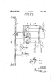
This inventionk has been; illustrated onI `the acconepanyi'ngA drawings: in which, `Fig"- 1 sheWs the invention` disclosed in an automatic i connection -establlshed between a callin-g Asubscriber and a 'called subscriberk'through switches Vindicated in. diagrammatic form, While Fig. 2 showsea circuit` arrangement for a inet-er embodying a modified form of the invention. i e
Referring'to this N'drawing the service meter 3. has been: shown Aassociated with the circuits cita calling subscribers' line' Whose setisindicated at l. The connection may be .established 4from this subscribesline through vline i finder LF, selector S and connector Cv to `the vcalledV subscril)erdev line AWhose set is, indicated 2. rllhese switches .and associated circuits V may be ort the usual type employediin`auto.-
it; metio telephone systemsin vWhichaground connectionV isestablished over the sleeve; conkdvuctors;fnv-lien*` the connection'V isf extended therethrough. Control circuits tortheservice meter 3 have l been shownassociatedWith the line. tinder-LFcontaining certain nter# ruptingdevicesl used in; the control.
The interruptingfdevice vrney be ,arranged Y' to closethrough spring contacts a connection to groundY once,` eatery ksix seconds For example, theground connections may loe-,closed for onefquarr second` and opened for five andjthreefquarter seconds.y The interrupting device 69 may' bei arranged `to close conneef tions to ground, fon-example, for one-quarter second and leave these. connections. open for two.-seconds. The two interrupting devices 5f :andy flnay bedriven byvany welllnowm timey regulated, constantly driven power inea-ns. The interrupting .devicei' may be arrangedto opera-te spring, contacts under control of. thefstepping magnet` 8. so that the connections are shifted once: Vevery sixtieth layK l0, letthand armature Vand back contacts ot theA cutfotf'relay llandthe tip and ring conductors throughthe subscribers loop atl. Relay l-lO inI operating ,closes aconnection to groundat its armature and front Contact4 to cause inthe usual manner a line finder such as LF toiconnect With the calling subscribers ce' Y line vand establish, the usual ground connec- Y tion onl the sleeve con ductor.
'n This ground connection new causes the operation of'cut-otl rel-ay 11 by closing the cirsus cui-t from. battery Winding of this relafytor ground through the sleeve terminal andV brush of the line finder LF. vvThe circuitfcr relayflOis thereby oenedat the leithand` armatures "and back contactsotfrelay-lll soi that relay 10 releases and the connection is now under control ot the ground on the sleeve of the line i'lnder While relay 11 is held operated by this ground. The service meter 3 which is of a marginal character will not operate in this circuit closed from ground and the sleeve through its Winding to battery 20.
The subscriber at 1 noW dials the number of the desired subscriber and the connection is thereby extended through the selector S and connector C to the called subscribers line at 2 in the usual manner. Vhile this connection is being extended the ground connection on the sleeve conductor is also extended through te the connectors in the usual manner. then the called subscriber answers the usual automatic ringing` by lifting the receiver otl" the switchhool, the talking connection is established through the tip and ring conductors between the two subscribers lines.
This talkingr connection now causes the operation of relay 12 which has a winding in each conductor. Operation of relay 12 initiates the functions of the control circuits for service meter 3 by closing a circuit for the operation of relay 13 as follows: Battery, righthand Winding of relay 13, armature and front contact of relay 12, inner lefthand armature 16 and back contact of relay t3. righthand armature and back contact of relay 14, upper closed contacts of the springs controlled by interrupter 7 and to ground through the lower springs controlled by interrupter 6. when this latter interrupter closes this connection. Such a closure may occur any time within two seconds after the operation of relay 12. This circuit for relay 13 only causes it to partially operate to close a connection for its lefthand Winding through its righthand armature 15 and front Contact to the ground on the sleeve conductor. As long as the original circuit for the relay 13 remains the lefthand Winding Will be short circuited, but when it is opened at the end of a one-quarter second period. the short-circuit is removed. The circuit for relav 13 Will then extend from battery through its righthand winding. armature and front contact of relay 12, lefthand winding of relay 13 and its ri ghthand armature 15 and front Contact to ground ou the sleeve at the connector. Both windings are now energized and the remaining armatures 16 and 17 of the relay are thereby attracted.
The contacts of interruptor 6 will now remain open for two seconds. At the end of this period the connections to ground are again established and a circuit completed for the operation of relay 18 from battery, Winding of this relay, inner lefthand armature 16 and front contact of relay 13, righthand armature and back Contact of relay 14;, upper normal contacts controlled by interrupter 7 and contacts controlled by interrupter 6 to ground. Relay 18 in operating opens the connection to ground for the sleeve conductor from the line finder and the calling subscribers line, at its righthand make-beforebreak contacts and establishes a connection to a so-called booster battery 19 through the righthand armature and front contact over the sleeve through the line finder. The service meter 3 is thereby operated as follows: from the booster battery 19 through the inner righthand armature and front Contact of relay 18, the sleeve conductor through the line finder, winding of the meter 3, a resistance to battery 2O of the opposite polarity, to battery 19, to ground. The service meter 3 in operating registers the first period of conversation. While battery is supplied from relay 18, the cut-off relay 11 will be maintained operated over the same circuit from the booster battery 19 and through the winding of relay 11 and the battery of the opposite polarity at the other end of this winding to ground. Relay 11 will therefore remain operated regardless of whether ground is connected to the sleeve 0r booster battery 19.
When relay 18 is released, due to the opening of the connection to ground at the interrupter 6, after the one-quarter second period service meter 3 is deenergized and the ground on the sleeve restored to maintain the cut-off relay 11 operated. It should be noted that on the operation of the service meter 3 a circuit is completed at its armature and front contact to ground. lVhen the booster battery connection is removed and ground is supplied on the sleeve the ground at the armature and front contact of meter 3 shunts the Winding of the meter 3 and partially short-circuits the battery 20. The release of the meter 3 is thereby greatly facilitated. A circuit will now be completed, due to the operation of the contacts, controlled by interrupter 7 when the magnet 8 releases on the release of relay 18, for the operation of relav 14 from battery, Winding of this relay, outer lefthand armature 17 and front Contact of relay 13 to ground at the middle contact of interrupter 7. Relay 14 in operating causes, due to the release of relay 18, a second circuit to be completed for the stepping magnet 8 from battery, winding of the magnet, outer lefthand armature and the first circuit is again closed.
3. In combination, two sources of current,
a magnet, a circuit for said magnet, means for closing said circuit from one source to ground said magnet remaining inoperative in said cir cuit, a second circuit for said magnet includ-` ing both said sources, means for substitutingA said second circuit for said first circuit, said magnet being operative in said second circuit, .a third circuit including a resistance and closed by the operation of said magnet from said first source through said resistance toy ground for rendering said first source ineffective to hold the magnet operated when thefirst circuit is again closed.
4. In combination, two sources of current, a magnet, a relay, a circuit for said magnet. and relay, means for closing said circuit from one source to ground, said magnet remaining inoperative and said relay operative in said circuit, a second circuit for said magnet and` relay including both said sources, means for substituting said second circuit for said first circuit, said magnet being operative and saidk relay remaining operative in said second circuit, a third circuit including a resistance and closed by the operation of said magnet from said first source through said resistance to ground for rendering said first source ineffective to hold the magnet operated and ineffective to release the relay which is held operated when the first circuit is again closed..
5. In combination, two sources of current of different potential, a magnet, a circuit for said magnet, means for closing said circuit from the lower potential source to ground, said magnet being inoperative in said circuit, a second circuit for said magnet including both said sources, means for substituting said second circuit for said first circuit, said magnet being operative iii said second circuit, a third circuit closed by the operation of said magnet for rendering said lower potential source ineffective to hold the magnet operated when said first circuit is again closed.
6. In combination, two sources of current of different potential, a magnet, a relay, a circuit for said magnet and relay, means for closing said circuit from the lower potential source to ground, said magnet remaining inoperative aiid said relay operative in said circuit, a second circuit for said magnet and relay concluding both said sources, means for substituting said second circuit for said first circuit, said magnet being operative and said relay remaining operative in said circuit, a. third circuit closed by the operation of said magnet for rendering said lower potential source ineffective to hold the magnet operative when said first circuit is again closed.
7. In combination, two sources of current, a magnet, a circuit for said magnet, means for closing said circuit from said source to ground, said magnet remaining inoperative in :said circuit, a second circuit for said magnet Yincluding both said sources, means for sub- :stituting said second circuit for said first circiiit said magnet being operative in said sec- \ond circuit, a third circuit closed by the operation of said magnet for shunting saidy Vfirst source from said magnet to hasten the irelease thereof when said first circuit is again iclosed.
S. In combination, three sources of current, :a magnet, a circuit for said magnet, means `for closing said circuit from a first source ito ground, said magnet remaining inoperative in said circuit, a second circuit for said imagnet including said first source and a second source, means for substituting said second circuit for said first circuit, said magnet `being operative in said second circuit, a third circuit closed by the operation of said magnet to include the first source and a third source for rendering said first source ineffective in `'holding the magnet operative and for rendering said third source effective in hastening the :release of the magnet when said first circuit fis again closed.
9. In combination, three sources of current, :a magnet, a relay, a circuit for said magnet .and relay, means for closing said circuit from :a first source to ground, said magnet being inoperative and said relay operative in said circuit, a second circuit for said magnet and ,relay including said first source and a second source, means for substituting said second circuit for said first circuit said magnet be- .ing operative and said relay remaining oper- :ative in said second circuit, a third circuit closed by the magnet in operating to include said first source and the third source for rendering said first source ineffective in holding the magnet and for rendering said second source effective in hastening the release of the magnet when the first circuit is again closed.
10. In combination, three sources of current, a magnet, a relay, a circuit for said magnet and relay, means for closing said circuit from a first source to ground, said magnet bleing inoperative and said relay being operative in said circuit, a second circuit for said magnet and relay including said first source and a second source, means for substituting said second circuit for said first circuit said magnet being operative and said relay remaining operative in said second circuit, a third circuit including a resistance closed by the operation of said magnet from said first source through said resistance to the third source for rendering said first source ineffective to hold the magnet operative and for rendering said third source effective to hasten the release of the magnet and without effecting the relay which is held operated when the first circuit is again closed.
11. In combination, two sources of current` a magnet, a resistance, a first circuit for said magnet, means for closing said first circuit g the magnet operated When the first circuit is from a irst lsource through said resistance to ground, said magnet remaining inoperative in said iirst circuit, a secondy circuit for said magnet, means for closing said second circuit in substitution of the first circuit from 'said first source through saidresistance to the other source, said magnet being operative in said second circuit, a third circuit, means responsive to ytheoperation of said magnet for closing said third circuitfrom said lirst source through said resistance to ground for rendering said first source ineffective to hold i source from said magnet to render saidV first source ineffective to hold the magnet operated and ineffective to release the relay Which is held operated When the first circuit is again closed.
In Witness whereof, I hereunto subscribe my name this 19th day of September,l 1930. LEWIS I-I. JOHNSONr
Priority Applications (1)
| Application Number | Priority Date | Filing Date | Title |
|---|---|---|---|
| US483824A US1851185A (en) | 1930-09-23 | 1930-09-23 | Telephone system |
Applications Claiming Priority (1)
| Application Number | Priority Date | Filing Date | Title |
|---|---|---|---|
| US483824A US1851185A (en) | 1930-09-23 | 1930-09-23 | Telephone system |
Publications (1)
| Publication Number | Publication Date |
|---|---|
| US1851185A true US1851185A (en) | 1932-03-29 |
Family
ID=23921663
Family Applications (1)
| Application Number | Title | Priority Date | Filing Date |
|---|---|---|---|
| US483824A Expired - Lifetime US1851185A (en) | 1930-09-23 | 1930-09-23 | Telephone system |
Country Status (1)
| Country | Link |
|---|---|
| US (1) | US1851185A (en) |
-
1930
- 1930-09-23 US US483824A patent/US1851185A/en not_active Expired - Lifetime
Similar Documents
| Publication | Publication Date | Title |
|---|---|---|
| US1831385A (en) | Telephone system | |
| US1851185A (en) | Telephone system | |
| US2344634A (en) | Telephone intercept system | |
| US2541589A (en) | Arrangement for disconnecting switching equipment from telephone lines | |
| US1804767A (en) | Telephone system | |
| US1831400A (en) | Telephone system | |
| US1383805A (en) | Party-line metering system for telephone-exchanges | |
| US1391588A (en) | Telephone-service system | |
| US1804766A (en) | Telephone system | |
| US1654923A (en) | Telephone system | |
| US1851139A (en) | Telephone system | |
| US2403877A (en) | Telephone line circuit | |
| US1575604A (en) | Manual telephone system | |
| US1852746A (en) | Telephone system | |
| US1818064A (en) | Telephone system | |
| US1658829A (en) | Telephone system | |
| US1462252A (en) | Telephone-signal-allotting system | |
| US1210314A (en) | Telephone toll system. | |
| US1215331A (en) | Telephone toll system. | |
| US1563556A (en) | Telephone system | |
| US2036316A (en) | Telephone system | |
| US904850A (en) | Telephone system. | |
| US867892A (en) | Telephone system. | |
| US1174262A (en) | Telephone system. | |
| US1221439A (en) | Telephone system. |