US1851180A - Display - Google Patents
Display Download PDFInfo
- Publication number
- US1851180A US1851180A US537557A US53755731A US1851180A US 1851180 A US1851180 A US 1851180A US 537557 A US537557 A US 537557A US 53755731 A US53755731 A US 53755731A US 1851180 A US1851180 A US 1851180A
- Authority
- US
- United States
- Prior art keywords
- light
- lamp
- lamps
- stenciled
- sheet
- Prior art date
- Legal status (The legal status is an assumption and is not a legal conclusion. Google has not performed a legal analysis and makes no representation as to the accuracy of the status listed.)
- Expired - Lifetime
Links
- 230000000694 effects Effects 0.000 description 12
- 239000011521 glass Substances 0.000 description 7
- 239000005337 ground glass Substances 0.000 description 6
- 241001417501 Lobotidae Species 0.000 description 4
- 241000287531 Psittacidae Species 0.000 description 3
- 238000010276 construction Methods 0.000 description 2
- 239000000203 mixture Substances 0.000 description 2
- 239000003086 colorant Substances 0.000 description 1
- 238000004040 coloring Methods 0.000 description 1
- 230000004927 fusion Effects 0.000 description 1
- 238000010438 heat treatment Methods 0.000 description 1
- 230000001788 irregular Effects 0.000 description 1
- 238000004519 manufacturing process Methods 0.000 description 1
- 230000004048 modification Effects 0.000 description 1
- 238000012986 modification Methods 0.000 description 1
- 229910052754 neon Inorganic materials 0.000 description 1
- GKAOGPIIYCISHV-UHFFFAOYSA-N neon atom Chemical compound [Ne] GKAOGPIIYCISHV-UHFFFAOYSA-N 0.000 description 1
- 239000002023 wood Substances 0.000 description 1
Images
Classifications
-
- G—PHYSICS
- G09—EDUCATION; CRYPTOGRAPHY; DISPLAY; ADVERTISING; SEALS
- G09F—DISPLAYING; ADVERTISING; SIGNS; LABELS OR NAME-PLATES; SEALS
- G09F13/00—Illuminated signs; Luminous advertising
Definitions
- k,Patenteci rMen i932 Emana.. 1L .nii-ritz; es# Banni), ILLNois, Assierion f'ro., lrmgivrumicoilon ,sIGN] may be noted the provision of a display in Y.Coi/mmm; orsLLoUrs, Missionar..ooarca'rionor'Mrssotmr j "DISPLAY y Y Y' Appiicaiionjmed May E15.,
- the invention accordinglyv comprises the Velements and combinations of elements, features of ⁇ construction, and arrangeinents'of parts Whichvvill V,be exempliiiedgin thestructhe 'following claims., Y
- Fig. l' isa front elevation ofthe invention
- Fig.: 2 ⁇ is a. View similar to Fig; l butshows a hinged front cover frame swung ⁇ down;
- Fig. 3 isl an lenlargedvertical section taken Fig. 4;' shows diagrammaticallyanfelectri Vcal'circuitcf the display;
- .5 is 1a detailed horizontal sectional I view takenvon line 5v-tof Fig; 3 With'certain parts yremoved and illustrating certain light- Flgz is Va View similar to Fig. 5 but showing; a modified form kof the invention. y Similar 'reference ⁇ A characters indicate corresponding parts throughoutgthe several' viewsy ot thel drawings.-
- the frame :l1 ishinged to aboX 5 Which'is made o-metalor Wood orithe like 6.
- the advertising kineanslrcornf prises a sheet .7 in which'is stenciled :("nuly kmerall) ythe desired'words'or pictures tobe 1 advertised.
- the stenciled Vportions provide rregions through .Which varied lightingeffects f be painted anattra'ctive color orbe provided v
- the .front of the sheet may thereof.: Behind thecard 7 Vis mounted .a
- panecf plain glass 13 which holds thecard v 7 'against the back surface :of thewpane-Q. 4,It isthus seen tha'tlight from thexinterior'of theboxgoes throughthek glassl, through the ⁇ sten'cilled vportions ll5 lof the card ⁇ 7,
- socketsv 17 are mountedalong theftop and bottom VWalls of the box 5.
- Variously colored lights 19' are mountedin the sockets .17, these being con- Vnectedin.parallel across an electric circuit 21l as "shown in Fig.y 4.
- Thermostatic controlsy inatically vary the intensity of the? lights 19;y
- the circuit 2l comprises lines 25 and 27 across l.Which ⁇ are connected thelights 19 and the thermostatic controls 23.y Y
- the thermostatic ⁇ controls 2,3 may comprise any thermostatic means for Avarying the current supply vtoa lamp, and in'this case com'- prise a thermostatic'element 29 ⁇ aroun ⁇ d which is Wound the resistance or across kthe Wires 25 4and 27, ⁇ a. Wire heating coil 3l, Y Wit-hthe lamp 19:;
- Ther strip 29 is adaptedfto make an electrical connection with an ad- 'ustable screw 35 mounted in the bridge 38 when said strip 29 is heated by the resistance 31.
- W'hen the lines 25 and 27 are connected to a source of electrical power (considering the line 25 to be at the higher potential) current fiows through the resistance 31, through the lamp 19 to the line 27, and the lamp burns dimly because of the resistance 31 in series with it.
- the element 29 is heated by the resistance 31 contact is made between the screw 35 and strip 29 and the resistance 31 is short circuited.
- the lamp 19 is connected directly to the line 25 by the line 36, the bridge 38, screw 35 and strip 29, whereby it receives the full potential across the lines 25 and 27 and accordingly burns far more brilliantly than when it did in series with the resistance 31.
- the element 29, no longer being heated by the resistance 31, cools and breaks contact with the contact
- the element 29 is now again heated by the resistance 31 which is cut into the circuit and the lamp 19 burns dimly.
- the screws 35 are provided to vary the distance through which the element 29 moves so that it fiashes at different time intervals.
- a bafile 39 is provided to protect the box from the heat.
- the baiiie 39 may be finished with a bright reflecting surfacewhereby the light from each lamp is reflected to all parts of the interior of vthe box and consequently against all parts of the card 7.
- the lamps 19 may be of any color such as green, red, blue, or yellow, as designated by the capital letters G, 1i, B and Y. These colors are in no sense limiting but are satisfactory for purposes of description.
- the frame 1 When the frame 1 is in a closed position a'nd the sheet 7 is in place, and the circuit 21 is connected to a source of power, projections or images of the stenciled portions 15 will be formed on the ground surface 11 of the glass pane 9 and will be continuously changing in color, as well as in width and in shading effect. This changing, moving coloring effect is brought about because at any instant a letter such as, for instance, the T in the word PARROT may be lighted primarily by the blue lamp directly behind it, the green lamp being off, but the yellow lamp being on.
- Fig. 5 there is shown a. specific example o the way in which the shading and color and the width of a letter may be changed by three lamps 19 without considering the light refiected from the baflies 39.
- Lamps having filaments 43 and comprising a blue, a red and a yellow lamp arranged as shown in Fig. 5 are to be used for example.
- the light from the red lamp when on will cover the area as shown by the bracket R.
- the light from the green lamp when on will cover the area shown b the bracket large G.
- the light from the b ue lamp when on will cover the area shown by the bracket large B.
- the image will be bordered by green and blue borders shown by the brackets g and b which will effectively shade o to yellow and purple respectively shown by the brackets R-l-Gr and R-l-B.
- the lamps along the kreaching 19 'are not arranged center line of the box 5 the light different portions of the length of 1w v length.
- the V'light i Cha'nemgf ,stenciled portion is different hence the Y coloring ⁇ effect ,changesl throughout ⁇ the l i' intensity ofen-the maybe varied' by; varying ythe'strength of theilainp's 19 vand/or by varyingfthe reflecting surface of the baffle 39jv
- thefbaifle'SQ may be ysupplantedby grouping smaller Alamps 19 in groups ybehind the,i light receiving por: ltions :or y'stencil 115," whereby the portion will always be lighted, andthe color effect always
- An' advantageof this arrangement ofthe advertising means 8 is ythat not only do the borders of wthe letters changec'olor, but also the w'idtlf'i of the letters constantlykchang'es, thereby providing
- this arrangement is adapted for night advertising where the daylight does not aii'ect the brilliancy of the sign.
- the dif-* fusion of the light through the ground glass lights up the whole surface of the ground I' glass to some extent, and this lighting effect is also constantly changing.
- the effectY f obtained is two-fold: (1) Projections or imagesV are formed ⁇ on-fthe ground glass sur'- facel 11 which are constantly changing; ⁇ (2) a liglitingefect of the ground glass ⁇ surface f 11 with various softe color mixtures vwhich make the whole sign most attractive at night; t is noted that this slight lighting leifect kof the ground glass surface 11 is not appreciably visiblein the daytime.
- a inodioation of fthe advertising means 3 isA shown whichfis adapted to give a more brilliant lighting effect of the letters or stencil portions 15 in the dayv light than wasgiven bythe arrangement of f the advertising meansv Sas shownfinlligs.
- the advertisingV means y 3 comprises a relatively thickinner sheet y55
- the word PARROT Next to the sheet v is placed a pane of glass k9 with its ground surface 11 next to the sheet 55.
- stenciled Aportions 53 which exactly corre- ⁇ spond with the stenciled portions 15 of the sheet 55.
- the outer surface 57 ofthe sheet 51 may bedecorated as desired to provide an artistic face.
- r n I ,As described in connection withthe example shown in Fig. 45, blue, red and greenlights k19 directly light the stencil portion 15 of the section of the sheet 55'shown'.
- the rays from the red lamp R fally directly on the ground" glass surface 11 ythrough the stencil portion Y 53.
- connectionl y setfoif to a greater advantage thelighted e letters and figures portrayedby the advere tising means 'A Y i Furthermore, reversing the positionvof ⁇ the rground surface 11, thatis, putting it next to the sheet55 'serves to provide a greater'depthl and to enhance tlieblocking and shading eii'ect n i i oftheimages formed bythe stencily portions 15.V It is to be understood, however, that in the modificationshowntiii Fig.V 6, the, ground glass surface l1 may be placed next to the sheet 51 ywhich .will .allowl a'f great-er area ⁇ l to be covered by the rays reflected from the side .walls 59,'and hence will provide wider borrdersforthe imagesl formedk by the stencilV portions 15'; Y n
- An advantage of the invention is the color eifect'obtained on the ground. glasslsurface ⁇ l1through the irregular lighting ofthe va-A rious lamps 19. The irregularity removes the monotony of a mechanical'blinker. Further', there are no Vmechanically drivenparts to The-sheet 7' or the sheets 55 and 5lY maybe wear out, and to raise the cost of production..v .l
- a display comprising regions to bc lighted, and electrical means adapted to light said regions, said means comprising lamps mounted in sockets, and automatic means adapted to irregularly vary the intensity of at least one lamp independently of other lamps, said regions comprising stenciled portions of a relatively thick sheet adapted to reflect light from the Walls of the stenciled portion and a ground surface adapted to substantially difliuse all of the light striking said surface whereby said surface is adapted to show images of said stenciled portions.
- a display comprising a circuit, a plurality of lamps connected therein, at least some lamps provided with lights of characteristics different from those of the others, flashers controlling the lamps, said flashers being timed indifferently with respect to one another, the display having at least one display aperture adapted to receive light from more than one lamp, said aperture having side Walls adapted to reflect some of said received light, and a project-ionr surface adjacent said aperture adapted to diffuse light coming through said aperture and reflected from the walls of said aperture.
- a display comprising a circuit, a plurality of lamps connected therein, at least some lam s provided with lights of characteristics t iffercnt from those of the others, flashers controlling the lamps, said flashers being timed indifferently With respect to one another, the display having at least one display aperture adapted to receive light from more than one lamp, said aperture having side walls adapted to reflect some of said received light, and a projection surface adjacent said aperture adapted to diffuse the light coming through said aperture and reflected from the walls of said aperture whereby an image of said aperture is formed, and means beyond said surface adapted to define said image.
- a display comprising regions to he lighted, electrical means adapted to light said regions, said means comprising lamps, automatic means adapted to discontinuously and irregularly vary the intensity of each lamp independently of all the other lamps, said regions comprising stenciled portions of an inner sheet, means adjacent said sheet adapted todiiuse light coming through said stenciled portions and reflected from the walls of said stenciled portions, and a relatively thin sheet adjacent said diffusing means having stenciled portions corresponding with said firstmentioned stenciled portions.
- a display comprising a stencil, a surface adapted to show an image projected by the stencil, walls on said stencil adapted to reflect light to form borders on said image, colored lamps adapted to supply light to said stencil, and means adapted to vary the color and intensity of the light delivered to said stencil and reflected from said walls.
Landscapes
- Physics & Mathematics (AREA)
- General Physics & Mathematics (AREA)
- Engineering & Computer Science (AREA)
- Theoretical Computer Science (AREA)
- Illuminated Signs And Luminous Advertising (AREA)
Description
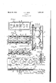
March 29, 1932. E. A. HEINZ 1,851,180.
" DISPLAY Filed May 15. 1931 FIG'.
H3A/n DE@ ya 55 RfG /f E 6km/Na GLHSS SURF/7c:
k,Patenteci rMen i932 Emana.. 1L .nii-ritz; es# Banni), ILLNois, Assierion f'ro., lrmgivrumicoilon ,sIGN] may be noted the provision of a display in Y.Coi/mmm; orsLLoUrs, Missionar..ooarca'rionor'Mrssotmr j "DISPLAY y Y Y' Appiicaiionjmed May E15.,
y T his invention fr'ieiates to. fadisplay5` and with regard to certain more specific features 'to a displayjprovidlng af Varying lighting effect." A
Among the severalobjects or" the invention Which,l the Yobserved lighting .effect is automaticallyv butirregularly'variable; the provision kof a vdisplay ofthe class described in Whichthe lighting Veffect iscontinuously varied by a `continuously varying source of light; and the provision ofy a display ofv the class described'w'hich is simple to manufac-V y ture and has no "mechanically driven parts. Other objectswill be in part obvious and in` y -part pointed yout hereinafter. f
Ving' effects; and,
The invention accordinglyv comprises the Velements and combinations of elements, features of` construction, and arrangeinents'of parts Whichvvill V,be exempliiiedgin thestructhe 'following claims., Y
y In the accompanying'drawings, in which are illustratedseveralof.various possible embodinients of the-invention', A
Fig. l' isa front elevation ofthe invention; Fig.: 2`is a. View similar to Fig; l butshows a hinged front cover frame swung` down;
Fig. 3 isl an lenlargedvertical section taken Fig. 4;' shows diagrammaticallyanfelectri Vcal'circuitcf the display;
.5 is 1a detailed horizontal sectional I view takenvon line 5v-tof Fig; 3 With'certain parts yremoved and illustrating certain light- Flgz is Va View similar to Fig. 5 but showing; a modified form kof the invention. y Similar 'reference`A characters indicate corresponding parts throughoutgthe several' viewsy ot thel drawings.-
It is desirable in interior VWindow displays I to use electric signsto attract attention. .For
Yreduced. IloWever, a
movement of some type, Whether of; vlight or thislpurpos'e' the ysofca'll'ed neon sign' Ais yin "manyl applications Vtoo.` brilliant-#The old Y blinker typeof sign has becomesousual V greatly' that yits advertising` valueahas been sign which provides a k*which coil 'is put inseries of means ...attracts attention.y 4Such of themfin'volve mechanically driven parts 'signs have been providedgbut because-many suchvsigns are expensive.y My invention pro- Which vthere is adapted to be mountedan ad-r` vertising means 3. The frame :l1 ishinged to aboX 5 Which'is made o-metalor Wood orithe like 6. The advertising kineanslrcornf prises a sheet .7 in which'is stenciled :("nuly kmerall) ythe desired'words'or pictures tobe 1 advertised. i
The stenciled Vportions provide rregions through .Which varied lightingeffects f be painted anattra'ctive color orbe provided v With additional advertisingg:ln` frontfoif thev sheet'or card .7, is mounted a paneoftglass 9y which has aground .surface llin the frontv may be lpassed The .front of the sheetmay thereof.: Behind thecard 7 Vis mounted .a
panecf plain glass 13 which holds thecard v 7 'against the back surface :of thewpane-Q. 4,It isthus seen tha'tlight from thexinterior'of theboxgoes throughthek glassl, through the `sten'cilled vportions ll5 lof the card `7,
through the glass. 9 .to the ground surface v11, Where.l the outline f of .the :stencil is formedrlf As shown in Figs2 and,4 socketsv 17 are mountedalong theftop and bottom VWalls of the box 5. Variously colored lights 19' are mountedin the sockets .17, these being con- Vnectedin.parallel across an electric circuit 21l as "shown in Fig.y 4. Thermostatic controlsy inatically vary the intensity of the? lights 19;y
f fis shown .in Fig. 4 kthe circuit 2l comprises lines 25 and 27 across l.Which `are connected thelights 19 and the thermostatic controls 23.y Y The thermostatic `controls 2,3 ,may comprise any thermostatic means for Avarying the current supply vtoa lamp, and in'this case com'- prise a thermostatic'element 29`aroun`d which is Wound the resistance or across kthe Wires 25 4and 27,` a. Wire heating coil 3l, Y Wit-hthe lamp 19:;
SGand-Ja metalbridge 38. Ther strip 29 is adaptedfto make an electrical connection with an ad- 'ustable screw 35 mounted in the bridge 38 when said strip 29 is heated by the resistance 31. W'hen the lines 25 and 27 are connected to a source of electrical power (considering the line 25 to be at the higher potential) current fiows through the resistance 31, through the lamp 19 to the line 27, and the lamp burns dimly because of the resistance 31 in series with it. As the element 29 is heated by the resistance 31 contact is made between the screw 35 and strip 29 and the resistance 31 is short circuited. Thus the lamp 19 is connected directly to the line 25 by the line 36, the bridge 38, screw 35 and strip 29, whereby it receives the full potential across the lines 25 and 27 and accordingly burns far more brilliantly than when it did in series with the resistance 31. The element 29, no longer being heated by the resistance 31, cools and breaks contact with the contact The element 29 is now again heated by the resistance 31 which is cut into the circuit and the lamp 19 burns dimly. The screws 35 are provided to vary the distance through which the element 29 moves so that it fiashes at different time intervals.
' Thus when the lines 25 and 27 are connected with a source of power the individual lights 19 .go off and on as' they are operated by the individual elements 29. The elements 29 not being mechanically timed with respect to one another do not operate according to definite cycles, that is, the time at which a certain light 19 may be on brightly or dimly .will change. Further, the relative times at which the various lights are on or oli is continuously changing, that is, they are indifferently timed. No definite cycle is established for a single lamp or for the lamps as a group. As will be ointed out hereinafter this comprises a de nite advantage.
When a resistance 31 is in series with a light 19 the light 19 burns so dimly as to be substantially ineffective and when in this condition the lights will be referred to, hereinafter, as being off; Then a resistance 31 is short circuited the light 31 will be said to be on. f
A bafile 39 is provided to protect the box from the heat. The baiiie 39 may be finished with a bright reflecting surfacewhereby the light from each lamp is reflected to all parts of the interior of vthe box and consequently against all parts of the card 7.
As shown in Fig. 2 the lamps 19 may be of any color such as green, red, blue, or yellow, as designated by the capital letters G, 1i, B and Y. These colors are in no sense limiting but are satisfactory for purposes of description. When the frame 1 is in a closed position a'nd the sheet 7 is in place, and the circuit 21 is connected to a source of power, projections or images of the stenciled portions 15 will be formed on the ground surface 11 of the glass pane 9 and will be continuously changing in color, as well as in width and in shading effect. This changing, moving coloring effect is brought about because at any instant a letter such as, for instance, the T in the word PARROT may be lighted primarily by the blue lamp directly behind it, the green lamp being off, but the yellow lamp being on. This results in a shading of some parts into a mixture of blue and yellow which is equivalent to green. Then ywhen the green li ht comes on the green portion of the letter will be reinforced or deepened. However, this cycle may not be repeated in connection with corresponding variations going on elsewhere in respect to the other letters because of the indifferent timing of the thermostatic switches one with respect to another.
This moving, lighting effect is brought about by the various rays of light which pass through the stenciled portions 15 to the surface 11. Thus a letter R in the word PARROT can receive light directly from as many as four or five of the lamps, and indirectly from substantially all of the lamps by means of the reflector or bafile 39. Because these various sources are continuously going on and 01T independently of each other the color and quantity of light which passes through the portion R is varied. Thus it is seen that at all times the color of the projections or images of the letters on the ground surface 11 is effected by the continuous changing of the lamps 19 from on to off or from off to on position.
Referrin to Fig. 5 there is shown a. specific example o the way in which the shading and color and the width of a letter may be changed by three lamps 19 without considering the light refiected from the baflies 39. Lamps having filaments 43 and comprising a blue, a red and a yellow lamp arranged as shown in Fig. 5 are to be used for example.
The light from the red lamp when on will cover the area as shown by the bracket R. The light from the green lamp when on" will cover the area shown b the bracket large G. The light from the b ue lamp when on will cover the area shown by the bracket large B. Thus at the moment when all three lights are on, the image will be bordered by green and blue borders shown by the brackets g and b which will effectively shade o to yellow and purple respectively shown by the brackets R-l-Gr and R-l-B.
If the green light goes off leaving the other two on the image will now comprise a red border shading to a purple and then to a blue, etc. As the lights 19 vflash on and off the images of the stenciled portions 15 will 'continuously change and appear to move or shift.
Because the lamps along the kreaching 19 'are not arranged center line of the box 5 the light different portions of the length of 1w v length. The V'light i Cha'nemgf ,stenciled portion is different hence the Y coloring` effect ,changesl throughout` the l i' intensity ofen-the maybe varied' by; varying ythe'strength of theilainp's 19 vand/or by varyingfthe reflecting surface of the baffle 39jv Further, thefbaifle'SQ may be ysupplantedby grouping smaller Alamps 19 in groups ybehind the,i light receiving por: ltions :or y'stencil 115," whereby the portion will always be lighted, andthe color effect always An' advantageof this arrangement ofthe advertising means 8 is ythat not only do the borders of wthe letters changec'olor, but also the w'idtlf'i of the letters constantlykchang'es, thereby providing a second moving effect. Furthermore, this arrangement `is adapted for night advertising where the daylight does not aii'ect the brilliancy of the sign. The dif-* fusion of the light through the ground glass lights up the whole surface of the ground I' glass to some extent, and this lighting effect is also constantly changing. Thus the effectY f obtained is two-fold: (1) Projections or imagesV are formed` on-fthe ground glass sur'- facel 11 which are constantly changing; `(2) a liglitingefect of the ground glass` surface f 11 with various softe color mixtures vwhich make the whole sign most attractive at night; t is noted that this slight lighting leifect kof the ground glass surface 11 is not appreciably visiblein the daytime. f K
.Referring now to Fig. 6, a inodioation of fthe advertising means 3 isA shown whichfis adapted to give a more brilliant lighting effect of the letters or stencil portions 15 in the dayv light than wasgiven bythe arrangement of f the advertising meansv Sas shownfinlligs.
3and5. Y, ,y j Y Y. i.
In this modification the advertisingV means y 3 comprises a relatively thickinner sheet y55,
which is thicker `than the rsheet 7 ,V- but which also has stenciled'portions 15 cut out to form,
' for example, the word PARROT Next to the sheet v is placed a pane of glass k9 with its ground surface 11 next to the sheet 55.
The outer layer of the advertising ineans f f-coinprises a relatively thin sheet 51 having, 5a
stenciled Aportions 53 which exactly corre-` spond with the stenciled portions 15 of the sheet 55. The outer surface 57 ofthe sheet 51 may bedecorated as desired to provide an artistic face. r n I ,As described in connection withthe example shown in Fig. 45, blue, red and greenlights k19 directly light the stencil portion 15 of the section of the sheet 55'shown'. The rays from the red lamp R fally directly on the ground" glass surface 11 ythrough the stencil portion Y 53. Rays from'the blue lamp B fallingat an angle on the thick side wally 59 of the stencil i portion 15 and the sheet 55 are refiected there-L fromkunto the @round surface 1v1.M Likewise v rays'from-the green lamp are reflected onto thegiound glass surface 11 opposite "l A' y wall 5 9. Thus, asshownby the brackets iR', 'Y
and R, plus B,"and R plus G, when all the lights 19Yare on, the portion of the surface 11 y ywhich is observed 'by 'a customer through the stencilportion 53 of the sheetlhas a central red portion, b'orderedby purple. andorange y bordersrespectively.r As hereinbefore vdel scribed, as the lights'19 iash on*`and off, 75" i this lighting effect onthe observed portion of`v the ground surface/1l changes. Itxisftof be Y understood that rays from the lights B and Y Gr also fall directly onthe ground glass sur-` face as explained in connectionwith the eX-pv ample shown in Fig.v 5.' Likewise, in Fig. 5, rays fallingon the `walls of the stenciledV por: tions 15,A are reflected onto the surface 11,`as just explained in connection with'` Fig. 6.
Such arefleotion was not shownp'in connectionl y setfoif to a greater advantage thelighted e letters and figures portrayedby the advere tising means 'A Y i Furthermore, reversing the positionvof` the rground surface 11, thatis, putting it next to the sheet55 'serves to provide a greater'depthl and to enhance tlieblocking and shading eii'ect n i i oftheimages formed bythe stencily portions 15.V It is to be understood, however, that in the modificationshowntiii Fig.V 6, the, ground glass surface l1 may be placed next to the sheet 51 ywhich .will .allowl a'f great-er area`l to be covered by the rays reflected from the side .walls 59,'and hence will provide wider borrdersforthe imagesl formedk by the stencilV portions 15'; Y n
An advantage of the invention is the color eifect'obtained on the ground. glasslsurface `l1through the irregular lighting ofthe va-A rious lamps 19. The irregularity removes the monotony of a mechanical'blinker. Further', there are no Vmechanically drivenparts to The-sheet 7' or the sheets 55 and 5lY maybe wear out, and to raise the cost of production..v .l
easily changed by removing them; from the means, and inserting new cards with different stenciling; or, in the secondV instance V,by f merely inserting a new card 51, havin'g the same stencil work but 'a diiferentdesign ,onl
the surface' 57. The provision ofan irregularly but substantially'y continuously chang-1 .ing image on'tlie ground glass surfacellfis 1 effective in attracting the attention. i The frame y1', where' they are held fbysuitable shifting` appearance is equally effective to accomplish this end.
In view of the above, it Will be seen that the several objects of the invention are achieved and other advantageous results attained. c
As many changes could be made in carrying out the above constructions Without departing from the scope of' the invention, it is intended that all matter contained in the above description or shown in the accompanying drawings shall be interpreted as illustrative and not in a limiting sense.
l claim:
l. A display comprising regions to bc lighted, and electrical means adapted to light said regions, said means comprising lamps mounted in sockets, and automatic means adapted to irregularly vary the intensity of at least one lamp independently of other lamps, said regions comprising stenciled portions of a relatively thick sheet adapted to reflect light from the Walls of the stenciled portion and a ground surface adapted to substantially difliuse all of the light striking said surface whereby said surface is adapted to show images of said stenciled portions.
2. A display comprising a circuit, a plurality of lamps connected therein, at least some lamps provided with lights of characteristics different from those of the others, flashers controlling the lamps, said flashers being timed indifferently with respect to one another, the display having at least one display aperture adapted to receive light from more than one lamp, said aperture having side Walls adapted to reflect some of said received light, and a project-ionr surface adjacent said aperture adapted to diffuse light coming through said aperture and reflected from the walls of said aperture.
3. A display comprising a circuit, a plurality of lamps connected therein, at least some lam s provided with lights of characteristics t iffercnt from those of the others, flashers controlling the lamps, said flashers being timed indifferently With respect to one another, the display having at least one display aperture adapted to receive light from more than one lamp, said aperture having side walls adapted to reflect some of said received light, and a projection surface adjacent said aperture adapted to diffuse the light coming through said aperture and reflected from the walls of said aperture whereby an image of said aperture is formed, and means beyond said surface adapted to define said image.
4. A display comprising regions to he lighted, electrical means adapted to light said regions, said means comprising lamps, automatic means adapted to discontinuously and irregularly vary the intensity of each lamp independently of all the other lamps, said regions comprising stenciled portions of an inner sheet, means adjacent said sheet adapted todiiuse light coming through said stenciled portions and reflected from the walls of said stenciled portions, and a relatively thin sheet adjacent said diffusing means having stenciled portions corresponding with said firstmentioned stenciled portions.
5. A display comprising a stencil, a surface adapted to show an image projected by the stencil, walls on said stencil adapted to reflect light to form borders on said image, colored lamps adapted to supply light to said stencil, and means adapted to vary the color and intensity of the light delivered to said stencil and reflected from said walls.
In testimony whereof, I have sivned my name to this specification this 22nd day of April, 1931.
ELMER A. HEINZ.
Priority Applications (1)
| Application Number | Priority Date | Filing Date | Title |
|---|---|---|---|
| US537557A US1851180A (en) | 1931-05-15 | 1931-05-15 | Display |
Applications Claiming Priority (1)
| Application Number | Priority Date | Filing Date | Title |
|---|---|---|---|
| US537557A US1851180A (en) | 1931-05-15 | 1931-05-15 | Display |
Publications (1)
| Publication Number | Publication Date |
|---|---|
| US1851180A true US1851180A (en) | 1932-03-29 |
Family
ID=24143117
Family Applications (1)
| Application Number | Title | Priority Date | Filing Date |
|---|---|---|---|
| US537557A Expired - Lifetime US1851180A (en) | 1931-05-15 | 1931-05-15 | Display |
Country Status (1)
| Country | Link |
|---|---|
| US (1) | US1851180A (en) |
-
1931
- 1931-05-15 US US537557A patent/US1851180A/en not_active Expired - Lifetime
Similar Documents
| Publication | Publication Date | Title |
|---|---|---|
| US2879614A (en) | Ultraviolet light illuminated sign and display devices | |
| US2262930A (en) | Illuminated instrument dial and the like | |
| JP2000502967A (en) | Panel with light transmission image | |
| US6149285A (en) | Interchangeable decorative tube device for fluorescent lighting | |
| KR20080079359A (en) | Advertisment display board and lighting | |
| US2344639A (en) | Illuminated display device | |
| US2345998A (en) | Combination animated day and night sign | |
| US5444932A (en) | Electric sign advertising element | |
| US1851180A (en) | Display | |
| US4989126A (en) | Illuminated outdoor advertising installation | |
| US1904850A (en) | Sign | |
| US2211571A (en) | Electric advertising device | |
| US1998857A (en) | Illuminated sign for day and night display | |
| KR100338715B1 (en) | light illumination display board and lamp shade displayed multiple illumination with engraved surface on transparent acrylic plastic plates | |
| JP3458118B2 (en) | Exhibition equipment | |
| US3640011A (en) | Flowing-light devices | |
| US1936734A (en) | Illuminated sign | |
| KR20100041723A (en) | Advertisment display board and lighting | |
| US2058312A (en) | Electrical advertising device | |
| US1878368A (en) | Advertising sign and the like | |
| US1429802A (en) | Advertising curtain for theaters | |
| US1904347A (en) | Sign | |
| US2152653A (en) | Luminous tube sign | |
| US1834066A (en) | Advertising sign | |
| US959440A (en) | Electrical sign. |