US1851174A - Radio system of communication - Google Patents
Radio system of communication Download PDFInfo
- Publication number
- US1851174A US1851174A US206330A US20633027A US1851174A US 1851174 A US1851174 A US 1851174A US 206330 A US206330 A US 206330A US 20633027 A US20633027 A US 20633027A US 1851174 A US1851174 A US 1851174A
- Authority
- US
- United States
- Prior art keywords
- frequency
- supersonic
- frequencies
- circuit
- oscillations
- Prior art date
- Legal status (The legal status is an assumption and is not a legal conclusion. Google has not performed a legal analysis and makes no representation as to the accuracy of the status listed.)
- Expired - Lifetime
Links
- 238000004891 communication Methods 0.000 title description 6
- 230000010355 oscillation Effects 0.000 description 38
- 230000003534 oscillatory effect Effects 0.000 description 23
- 238000004804 winding Methods 0.000 description 12
- 230000005540 biological transmission Effects 0.000 description 7
- 238000001914 filtration Methods 0.000 description 4
- 230000008878 coupling Effects 0.000 description 3
- 238000010168 coupling process Methods 0.000 description 3
- 238000005859 coupling reaction Methods 0.000 description 3
- 238000005562 fading Methods 0.000 description 3
- RTZKZFJDLAIYFH-UHFFFAOYSA-N Diethyl ether Chemical compound CCOCC RTZKZFJDLAIYFH-UHFFFAOYSA-N 0.000 description 2
- 238000010438 heat treatment Methods 0.000 description 2
- 238000000034 method Methods 0.000 description 2
- 230000000737 periodic effect Effects 0.000 description 2
- 230000001172 regenerating effect Effects 0.000 description 2
- 230000005236 sound signal Effects 0.000 description 2
- 230000001131 transforming effect Effects 0.000 description 2
- 230000000694 effects Effects 0.000 description 1
- 230000001939 inductive effect Effects 0.000 description 1
- 229920000136 polysorbate Polymers 0.000 description 1
- 235000002020 sage Nutrition 0.000 description 1
- 230000003068 static effect Effects 0.000 description 1
Images


Classifications
-
- H—ELECTRICITY
- H04—ELECTRIC COMMUNICATION TECHNIQUE
- H04B—TRANSMISSION
- H04B14/00—Transmission systems not characterised by the medium used for transmission
- H04B14/08—Transmission systems not characterised by the medium used for transmission characterised by the use of a sub-carrier
Definitions
- Fig. 1 is a sending station, Fig; 2 a receiving station, Fig. 8 a modified form of receiving station, and Fig. 4 a receiver adapted to receive both of the types of transmission emitted. by the transmitter of Fig. 1. r
- the sending stations emit oscillatory energy of peculiar wave form.
- the energy may betransmitted through the ether to one or more receiving stations, on which it can be impressed by means of an antenna and ground or counterpoise or by means of wire connections in'a manner well known in the wire communication art.
- the emitted energy is in the form of electric waves of which the main or carrier high frequency is generatedby an oscillator shown within the rectangle 15.
- a'series-of periodic amplitude variations of lower but supersonic frequency these being generated by an oscillator such for instance as is shown within the rectangle .16.
- One or more additional series of periodic amplitude variations are also impressed on the first high frequency, and each ofrthese are also of lower but supersonic frequencygthe lower supersonic frequencies differ from each other so that there shall be substantially no interference.
- They are each generated by anoscillator such for instance as is-shown within the rectangle 17 which is of the same character as the oscillator 16 but has different values of inductance and capacity so as to generate the frequency desired.
- the output current of the oscillator 16 is passed to a modulator such for instance as is-shown within the rectangle 20 and which consists of two three element vacuum tubes and transformers, by. which the current is 1927. Serial No. 206,330.
- the modulator20 thus produces a modified current having the variations and characteristics of the signal currents, but transformed or stepped up into a supersonic frequency range. If the signal currents are those of voice or music or the like, such as areproduced by a transmitter 22 they will have frequencies of from about 200 to about 2,000 cycles per second, and will be stepped up into a higher range according to the frequency of current produced by the oscillator 16. For example, if this oscillator produces a frequency of 20,000 cycles per second, the
- the output of the filter 25 is connected to a modulator 35 by which the supersonic frequencies transmitted through the filter are caused to modulate the very high frequency or carrier current generated by the oscillator 15 and amplified by the amplifier 58-.
- the output of the oscillator 17 is modulated by a modulator shown within the rectangle 40 according to signal current produced by a signal transmitter shown within the rectangle 4:1.
- This modulator is of a type in which the oscillator cur rent acts upon the modulator continuously but it is torbe understood that a push-pull type of modulator similar to that shown atQO for use with the output of the oscillator 16'may be used here.
- the signal transmitterel is of a type which .produces a current of a single frequency and therefore afilter of this type is not necessary;
- the modulated current resultingfrom the modulation of the energy generatedby the oscillator l-O as modulated by the signal current produced by the signal transmitter 41 is impressed upon the modulator 35 by which the supersonic frequencies are caused to modulate the very high frequency carrier current which was generated by oscillator 15 and was wobbled without change in amplitude by the circuit v50 as disclosedv inid'etail hereinafter.
- Thefrequency of the oscillation of a tube generator of the type described depends among other things upon the value of the mean'grid voltage and the mainplate voltage .during a radio frequency cycle. With wobbler 50 noteXc-ited there will be'a certain frequency produced in the oscillatory circuit 51', 52, depending among other things on the voltage of the batteries 58 and 54:. With Wobbler 50 operating, alternating voltages are impressed upon the grid and plate circuits of the tube 55 and thus superimposed on the direct current voltages of the sources 53 and 54. The frequency is determined by the instantaneous voltages impressed upon the grid and plate circuits respectively due to the voltage sources 50, 53 and 54.
- the middle adjustable terminal or slider of the potentiometer 56 is provided to determine the relative voltages applied to said gridand plate circuits due to generator 50. By proper adjustment thereof and of rheostat 57, it is found that the generator 50 produces variations in thefrew quency of radio current in the oscillatory circuit 51, 52, withsubstantially no variation in amplitude.
- the frequency generated by the. high frequency oscillator will be wobbled or Varied at an audible rate and-thus a person receiving on an ordinary receiver will receivea garbled message.
- the frequency generated by the high frequency oscillator 50 When the Wobbler oscillator 50 is operating at a supersonic frequency the frequency generated by the high frequency oscillator will be wobbled and varied at a supersonic rate and thus due to the change in fading patterns for various frequencies the fading pattern of the transmitter will be shiftedat a supersonic or radio frequency rate and a receiver capable of receiving the range of frequencies emitted by the transmitter will receive a signal which will be free from fading.
- means forreceiving radiant energy such asantenna 101 and a counterpoise or ground 102 included in the pler 104.
- the coupler 104 has asecondary winding 105 which, in combination with .a. variable condenser 106, is included in the closed oscillatory circuit 107 which may be tuned to a frequency ofthe high frequency .85 circuit ,ofwhich, is a winding 103 of the couoscillator-the electromagnetic waves of which t is desired to receive.
- These circuits are so broadly tuned as to receive with practically equal intensity over the entire range'of wobble of the Wobbler system, it being understood that the selectivity is attained in this system by tuning for quency.
- the detector 110 may be of the vacuum tube type having a filament 113'for emitting electrons, a grid 114 for controlling the pass sage of electrons and a plate 115 upon the electrons may impinge.
- a potentiometer 116' controls. anormal potential onthe grid circuit 120 which is" connected to the input circuit of the supersonic detector 121, which may be of the same type as detector 110.
- the output circuit of the detector121 may be tuned to arelatively low frequency current, of the frequency of the signal currents employed, or may be untuned,and'in any case is inductively coupled by means of a coupling l22to an indicator circuit which may comprise an amplifier 123 controlling a signal relay 12 1 which in turn closes local circuits of a control magnet or other indicating device 125.
- the output circuit of the detector 121 may include an indicating devise such as a telephone receiver 126 for the reception of speech or telegraphic code signals.
- One of the fields of usefulness of the invention is in the control by a magnet 125 of a desired utility, such as the rudder 127 of a dirigible body, engine throttle or the like.
- FIG. 3 A modified form of receiving circuit is shown in Fig. 3.
- This circuit consists of an antenna circuit which includes an inductance 103 coupled to a closed oscillatory circuit 107 comprising an inductance 105 and a variable condenser 106, the inductance 103 is also variably coupled to an inductance 117.
- the closed oscillatory circuit 107 is connected to the input circuit of a thermionic device 110 having the usual filament 113 for emitting electrons, theplate 115 on which the electrons impinge and a grid 11 1 for controlling the passage of theelectrons.
- the filament 113 of the thermionic device 110 may be heated by a current supplied by a battery 111 and controlled by the variable resistance 112, and is shunted by a potentiometer 116 having a slider connected with the closed oscillatory circuit 107 whereby the normal potential maintained upon the grid 114 relative to the filament 113 may be adjusted.
- the output circuit of the thermionic device 110 includes the inductance 117 and a closed oscillatory circuit 118 comprising an inductance and a condenser in shunt therewith. The other end of this oscillatory circuit 118 is connected to the positive pole of a source of direct current 119 for maintaining a positive potential upon the plate 115 of the thermionic device 110 relative to the filament 113.
- the thermionic device 128 is connected with the inductively coupled circuits so that it acts as a regenerative oscillator.
- the inductive coupling be tween these circuits comprises a transformer 129 one winding of which is shunted by variable condenser 130 by means of which the oscillations generated may be made of the same frequency as the currents produced by the generator 16 at the sending station as shown in Fig. 1.
- the output circuit of the oscillator 128 includes the closed oscillatory circuit formed by the winding of a transformer 129 and the variable condenser 130 and also the primary winding of a transformer 131.
- the other end of the primary winding of the transformer 131 is connected to the positive terminal of the plate potential source 119 whereby the plate of the thermionic device 128 is maintained at a positive potential relative to the filament.
- the potentiometer 132 is connected across the filament heating battery 111 and includes a slider 133 connected to the secondary winds ing 134 of a transformer 135 and a variable condenser 136 forms with this winding 131 a closed oscillatory circuit, the other end of which is connected through the secondary winding of a transformer 131 withthe input circuit of a thermionic device 121.
- the oscillator 128, 129, 130, in combination with the transformer 131 forms a homodyne for impressing upon the input circuit of the thermionic device 121 an oscillatory E. M. F. corresponding in frequency to that of the suppressed currents produced by the generator 16 at the transmitting station.v r
- the output circuit of the thermionic device 121 is connected to an indicating device which as shown is a telephone receiver 126 provided with a bypass condenser 137.
- This output circuit also includes a connection .between the indicating device and the positive terminal ofthe potential source 119.
- the radiant energy intercepted by the antenna circuit induces oscillations in the closed oscillatory circuit 107 which is tuned to be responsive to the radiated energy of the'sendin'g station.
- the slider of the potentiometer 116 is so adjusted that the thermionic device 110 produced on a curved portion of its characteristic curve and thus the device 110 acts to detect or rectify these oscillations.
- Its output circuit transmits these rectified oscillations through the inductance 117 so that its transmitted oscillations are regeneratively amplified.
- the superimposed current flowing in this output circuit varies in amplitude according to the modulation impressed upon the carrier wave of the sending station and there appears upon the primary winding of the circuit 18 of the intervalve transformer 135 a uni-directional current having the frequencies and characteristics of the unsuppressed side band of modulated lower supersonic frequency of the sending station.
- the closed oscillatory circuit 120 is tuned to these frequencies by adjusting the condenser included therein.
- the thermionic device 128 with its connected circuits forms a homodyne which impresses upon the input circuit of the thermionic device 121 an osc'illatory E. M115. corresponding in frequency to that of the suppressed currents produced by the generator 16 of the transmitting staso adjusted that the thermionic device 121 operates on a curved portion of the characteristic curve to cause 'it to detect or rectify these combined oscillations impressed upon the input circuit.
- currents varying in amplitude in accordance with the signal currents. These currents cause the telephone 126 to produce sound waves of the same character as those which operatethe signal transmitter'21 or of the same character as that produced by thetrans mitter 41 of the transmitting station as shown in Fig. 1.
- the antenna circuit'101, 102, 103 is broadly tuned to the carrier or high frequency so as to include all of the frequencies of wobble.
- Inductively coupled with the coil 103 of the antenna circuit is the input circuit of the regenerative detector 140 which is connected in the usual 7 and well known manner.
- the output circuit of the detector 140 includes the inductances 141 and 142 which are inductively coupled respectively to the input 143 and 144 of the intermediate frequency amplifiers 145 and V 146.
- the outputs of the amplifiers 145 and 146 are inductively coupled to the inputs of the second detectors 147 and 148 respectively
- the detector 147 is for detecting the secondary supersonic frequencies of the channel P communications and the output of this detector is coupled through the usual audio transformer and audio frequency amplifier 151 which in turn is connected to the receiving device 153.
- the input of the second detector 148 for use with channel Q, messages includes the inductance 150 to which is inductively coupled the out 3-ut of a local oscillator indicated at 149.
- This oscillator 149 which may be of any appropriate type is adjusted to thesecondary or supersonic frequency which has been removed from the channel Q, type message by the filter 26.
- the output of the detector 148 is coupled through the usual audio frequency transformor to the amplifier tube 152 which in turn is connected in the usual manner to the indicator 154 for receiving the Q, signal.
- the receiver shown in 4 is capable of receiving signals which have been transmitted by either of the two transmitters included in the transmitter of Fig. 1, that including the local oscillator 149 being adapted to receive signals of the Q type which have had the secondary frequency carrier produced by the oscillator 16 removed I by the filter 25.
- the receiving apparatus of an unauthor ized station cannot be adjusted to receive a true message unless definite knowledge'lis available as to the carrier frequency employed as well as the lower, supersonic. frequency 1 sed.
- An unauthorized station cannot mease ure and determine the lower supersonic-frequ-ency of the transmitting station because of the facts that when signals are not being impressed, currents of this frequency areneutralized' and are not emitted in the transmitted station, furthermore when the wob-t bling device of a wobbling circuit islem ployed the emitted energy is further distort-ed.
- WVhat I claim is: 1.
- a method of radio transmission which comprises generating a high frequency car cy and combiningit with the detected high frequency carrier wave and detecting the re sultant Wave and thereby reproducing the same audio signals as those which modulated said secondary supersonic frequencies.
- a method of radio transmission which comprises generating a carrier frequency, wobbllng sald carrier frequency at a supersonic fre uencv without chan e in am litude thereof, generating a plurality of supersonic secondary frequencies, modulating each of said secondary frequencies at'an audio fre-, quency, filtering the modulated secondary frequencies, and modulating the constant amplitude supersonic wobbled carrier frequency I with said filtered audio modulated secondary frequencies.
- a system of radio transmission which comprises generating a carrier frequency, wobbling said carrier frequency at a supersonic frequency without change in amplitude thereof, generating a plurality of supersonic secondary frequencies, modulating each of said secondary frequencies at an audio frequency, filtering the modulated secondary frequencies, and modulating the constant amplitude supersonic wobbled carrier frequency with said filtered audio modulated secondary frequencies, transmitting the thus modulated carrier frequency, receiving the Waves transmitted, detecting said high frequency carrier Wave, supplying the secondary supersonic frequency and combining it with the detected high frequency carrier wave and detecting the resultant wave and thereby producing the same audio signals as those which modulated said secondary supersonic frequencies.
- Apparatus for emitting radiant energy comprising a generator of high frequency oscillations, means including a plurality of generators of oscillations of a plurality of different frequencies for producing in said high frequency oscillations amplitude variations of supersonic frequencies varying in accordance with telephonic signals, and means for wobbling the frequency of the high frequency oscillations, at a supersonic frequency without change in amplitude thereof.
- a radio system comprising a sending station having a generator of high frequency oscillations, a plurality of generators for generating oscillations of different frequencies, a push-pull modulator interposed between each of said generators, a signal transmitter arranged when operated to produce side bands from said oscillations of different fre quency, means for suppressing one of said side bands, means interposed between said suppressing means and the generator of high frequency oscillations for producing amplitude variations in the high frequency oscillations in accordance with each of the unsuppressed side bands, and a Wobbler for harmonically varying the frequency of the high frequency oscillations at a supersonic frequency and a receiving arrangement having an element arranged to intercept said waves, a closed oscillatory circuit responsive to said high frequency oscillations, another closed, oscillatory circuit tuned to the signal-controlled amplitude variations produced in the high frequency oscillations, a generator of oscillations corresponding with the oscillations of said different frequency associated with said other closed oscillatory circuit, and means for transforming the energy set up in said
- An apparatus for the transmission of intelligence comprising a transmitting station and a plurality of receiving stations, said transmitting station comprising a thermionic oscillator arranged to produce high frequenoy oscillations, a second thermionic oscillator for producing supersonic oscillations, said oscillations being adapted to varythe fre quency characteristics'ofi said first mentioned oscillator without changing the amplitude of its oscillations, a plurality of supersonic secondary frequency generators adapted to produce oscillations of different frequencies, a
- thermionictube modulator wherein th'ehigh waves, ajclcsed oscillatory circuit responsive to said high frequency oscillations, another closed, oscillatory circuit tuned to the signal-controlled amplitude variations produced int-he high frequency oscillations, a genera tor of oscillations corresponding with the oscillations of said different frequency associated with said other closed oscillatory cir cuit, and means'for transforming 'the energy setup in said circuits into sensible'm'anifestations and operating a mechanical device thereby.
- An apparatus for the transmission of in teui ence comprising atransmitting station and 'a plurality of"receiving stations, said transmitting station comprising a thermionic oscillatcr a ra g t p oduc high q y oscillations, a second thermionic oscillator for producing supersonic oscillations, said oscillations being adapted to vary the frequency characteristics of said first mentioned oscillator without changing the amplitude of its oscillations, a plurality of supersonic secondary frequency generators adapted to produce oscillations of different frequencies, a signal transmitter adapted to modulate each of said supersonic carrier frequency generators, a filter arranged to suppress said secondary carrier frequency and one side band from the modulated secondary frequency wave, a thermionic tube modulator wherein the high frequency oscillations generated by said first mentioned oscillator is adapted to be modulated by each of the side bands transmitted through the above mentioned filters, and an antenna circuit adapted to be energized by the high frequency carrier wave
- a thermionic detector comprising a filament a grid and a plate, the grid of which is connected to said secondary circuit and the plate of which is connected to aninductance likewise inductlvely coupled to said inductance in said last mentioned antenna circuit and which is tuned to a frequency of one of said supersonic secondary' frequency generators and through said inductance to an oscillator circuit and through a source of high potential, said lastmentioned oscillator circuit inductively coupled to another oscillator circuit which in turn is connected through an inductance to the grid of a secondary thermionic detector and a supersonic frequency generator adapted to generate the same frequency as one with said supersonic secondary frequency generators of saidtransmission station, the output of which is inductively coupled to said last men- I tioned inductance;
- a system of transmitting intelligence by radiant energy comprising a vacuum tube having a grid and a plate, means included in the circuits of the grid and plate of said tube for producing therein an oscillatory current of substantially constant amplitude and for varying the frequency of said current at a supersonic rate by varying proportionately the grid voltage and the plate voltage of said tube, a plurality of secondary frequency generators, means for modulating each of said secondary frequencies at an audio frequency, means-for filtering undesired side bands from said modulated secondary frequencies, and means for modulating said supersonic wobbled carrier frequency by said filtered audio modulated secondary frequencies,
Landscapes
- Engineering & Computer Science (AREA)
- Computer Networks & Wireless Communication (AREA)
- Signal Processing (AREA)
- Arrangements For Transmission Of Measured Signals (AREA)
Description
March 29, 1932- J. H. HAMMOND, JR 1,851,174
RADIO SYSTEM OF COMMUNICATION Filed July 16, 1927 4 Sheets-Sheet 1 m n m w u M m m Nm n m M 0 m m m n r :JA In my w m 9.5 m -I- .-m&-k%. %%m: wt--. w fi v i 1 m 1 .m I: km -J m m m u H m n m m H u m m m m. u m M m m m n m? ,1, n g u n m U Q L! m T. m m W m M W W m uuwwm m -1 mwwmw n gfi m 32 .xa Emfi QSBESQ 1927 4 Sheets-Sheet '2 7 March 29, 1932. J. H. HAMMOND, JR
RADIO SYSTEM OF COMMUNICATION A Filed July 16 INVENTOR I JOHN HAYS HAMMOND JR- BY [fa/m d ATTORNEY IEIEI I IBI lint: unl
March 1932- J. H. HAMMOND, JR
RADIO SYSTEM OF COMMUNICATION Filed Jul y l6 1927 4 Sheets-Sheet n u'unulhl INVEN TOR. JOHN HAYS HAMMOND JR.
dam/ 4 ORNEY March 29, 1932. J HAMMOND, JR 1,851,174
RADIO SYSTEM OF COMMUNICATION Filed July 16. 1927 4 Sheets-Sheet 4 I I I I 0/0/0170 E E B l I I I I I I a/mm amwa 0 INVENTOR JOHN ms HAMMOND JR BY 92a (441W AT ORNEY Patented Mar. 29, 1932 JOHN HAYS HAMMOND, JR., OF GLOUCESTER, MASSACHUSETTS RADIO SYSTEM or COMMUN CATION Application filed July 16,
systems of V proved'freedom from static, wobbling of frequencies especially without much change in current strength, the filtering of currents of bands'of frequencies desired, and other 0bj'ects appearing in the following description; g
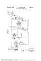
In the drawings, Fig. 1 is a sending station, Fig; 2 a receiving station, Fig. 8 a modified form of receiving station, and Fig. 4 a receiver adapted to receive both of the types of transmission emitted. by the transmitter of Fig. 1. r
The sending stations emit oscillatory energy of peculiar wave form. The energy may betransmitted through the ether to one or more receiving stations, on which it can be impressed by means of an antenna and ground or counterpoise or by means of wire connections in'a manner well known in the wire communication art.
Referring now more particularly to Fig. 1, the emitted energy is in the form of electric waves of which the main or carrier high frequency is generatedby an oscillator shown within the rectangle 15. 'Upon these waves there is impressed a'series-of periodic amplitude variations of lower but supersonic frequency, these being generated by an oscillator such for instance as is shown within the rectangle .16. One or more additional series of periodic amplitude variations are also impressed on the first high frequency, and each ofrthese are also of lower but supersonic frequencygthe lower supersonic frequencies differ from each other so that there shall be substantially no interference. They are each generated by anoscillator such for instance as is-shown within the rectangle 17 which is of the same character as the oscillator 16 but has different values of inductance and capacity so as to generate the frequency desired.
The output current of the oscillator 16 is passed to a modulator such for instance as is-shown within the rectangle 20 and which consists of two three element vacuum tubes and transformers, by. which the current is 1927. Serial No. 206,330.
modulated by a signal transmitting circuit such as is shown within the rectangle 21. The modulator20 thus produces a modified current having the variations and characteristics of the signal currents, but transformed or stepped up into a supersonic frequency range. If the signal currents are those of voice or music or the like, such as areproduced by a transmitter 22 they will have frequencies of from about 200 to about 2,000 cycles per second, and will be stepped up into a higher range according to the frequency of current produced by the oscillator 16. For example, if this oscillator produces a frequency of 20,000 cycles per second, the
output of the modulator 20 produces a cur rent which is resolvable into 20,200 to 22,000 (because 20,000+ (200 to 2,000) =20,200 to 22,000) and 20,000 and 19,800 to 18,000 (because 20,000 (200 to 2,000) =19,800 to 18,000 cyclesrespectively) Furthermore these currents appear in the output of the modulator 20, only when the transmitter 22 is rendered active. i A desired bandof these frequencies can be filtered out by an electric wave filter shown within the rectangle-25. This consists of two couplings 26 and 27, the secondary (right hand) windings of which are included in oscillatory circuits 28, 29, respectively. These two oscillatory circuits are made resonantto a desired upper anddesired lower frequency respectively, as for example in the case cited, to 19,800 and 18,000 cycles, and while the primary (left hand) windings are wound in the same direction, the secondary (right hand) windings are wound'oppositely, so that cur rents of a frequency outside these frequencies are suppressed. Currents of the selected frequencies, as well as currents of frequencies lying between them are transmitted. A condenser 30 assists in this transmission when the two frequencies selected lie far apart.
The output of the filter 25 is connected to a modulator 35 by which the supersonic frequencies transmitted through the filter are caused to modulate the very high frequency or carrier current generated by the oscillator 15 and amplified by the amplifier 58-.
In a similar way the output of the oscillator 17 is modulated by a modulator shown within the rectangle 40 according to signal current produced by a signal transmitter shown within the rectangle 4:1. This modulator is of a type in which the oscillator cur rent acts upon the modulator continuously but it is torbe understood that a push-pull type of modulator similar to that shown atQO for use with the output of the oscillator 16'may be used here. However in this instance the signal transmitterel is of a type which .produces a current of a single frequency and therefore afilter of this type is not necessary; The modulated current resultingfrom the modulation of the energy generatedby the oscillator l-O as modulated by the signal current produced by the signal transmitter 41 is impressed upon the modulator 35 by which the supersonic frequencies are caused to modulate the very high frequency carrier current which was generated by oscillator 15 and was wobbled without change in amplitude by the circuit v50 as disclosedv inid'etail hereinafter. l
Thefrequency of the oscillation of a tube generator of the type described depends among other things upon the value of the mean'grid voltage and the mainplate voltage .during a radio frequency cycle. With wobbler 50 noteXc-ited there will be'a certain frequency produced in the oscillatory circuit 51', 52, depending among other things on the voltage of the batteries 58 and 54:. With Wobbler 50 operating, alternating voltages are impressed upon the grid and plate circuits of the tube 55 and thus superimposed on the direct current voltages of the sources 53 and 54. The frequency is determined by the instantaneous voltages impressed upon the grid and plate circuits respectively due to the voltage sources 50, 53 and 54. g The middle adjustable terminal or slider of the potentiometer 56 is provided to determine the relative voltages applied to said gridand plate circuits due to generator 50. By proper adjustment thereof and of rheostat 57, it is found that the generator 50 produces variations in thefrew quency of radio current in the oscillatory circuit 51, 52, withsubstantially no variation in amplitude.
When the Wobbler oscillator 50 is operating at a low or audio frequency the frequency generated by the. high frequency oscillator will be wobbled or Varied at an audible rate and-thus a person receiving on an ordinary receiver will receivea garbled message.
When the Wobbler oscillator 50 is operating at a supersonic frequency the frequency generated by the high frequency oscillator will be wobbled and varied at a supersonic rate and thus due to the change in fading patterns for various frequencies the fading pattern of the transmitter will be shiftedat a supersonic or radio frequency rate and a receiver capable of receiving the range of frequencies emitted by the transmitter will receive a signal which will be free from fading.
Thus there are impressed upon the antenna two high frequency wave-forms which are wobbled and which are modulated at supersonic frequencies, which frequencies have been modulated at signal frequencies. It is to be understood that a'plurality of secondary frequencies may be used for transmitting as many signals and that the secondary carrier wave's may-eitherbe transmitted as for the signal sent by the transmitter 41, known as a P channel or may be suppressed as with the signal sent by, the transmitter 21 known as a Q channe.
In the form ofreceiving stationshown in Fig.2 for the reception of P channel messages there. is provided means forreceiving radiant energy, such asantenna 101 and a counterpoise or ground 102 included in the pler 104. The coupler 104 has asecondary winding 105 which, in combination with .a. variable condenser 106, is included in the closed oscillatory circuit 107 which may be tuned to a frequency ofthe high frequency .85 circuit ,ofwhich, is a winding 103 of the couoscillator-the electromagnetic waves of which t is desired to receive. These circuits are so broadly tuned as to receive with practically equal intensity over the entire range'of wobble of the Wobbler system, it being understood that the selectivity is attained in this system by tuning for quency.
Fo I detectingthe energy of relatively high the secondary carrier. frer frequency waves and producing therefrom an f oscillating current of the lower but supersonicv frequency impressed thereon, th'ere'is provid ed a detector110 having a filament heating battery 111 and a filament control rheostat 112. The detector 110 may be of the vacuum tube type having a filament 113'for emitting electrons, a grid 114 for controlling the pass sage of electrons and a plate 115 upon the electrons may impinge. A potentiometer 116' controls. anormal potential onthe grid circuit 120 which is" connected to the input circuit of the supersonic detector 121, which may be of the same type as detector 110. 1 The output circuit of the detector121may be tuned to arelatively low frequency current, of the frequency of the signal currents employed, or may be untuned,and'in any case is inductively coupled by means of a coupling l22to an indicator circuit which may comprise an amplifier 123 controlling a signal relay 12 1 which in turn closes local circuits of a control magnet or other indicating device 125. If desired, the output circuit of the detector 121 may include an indicating devise such as a telephone receiver 126 for the reception of speech or telegraphic code signals.
.One of the fields of usefulness of the invention, however, is in the control by a magnet 125 of a desired utility, such as the rudder 127 of a dirigible body, engine throttle or the like.
A modified form of receiving circuit is shown in Fig. 3. This circuit consists of an antenna circuit which includes an inductance 103 coupled to a closed oscillatory circuit 107 comprising an inductance 105 and a variable condenser 106, the inductance 103 is also variably coupled to an inductance 117. The closed oscillatory circuit 107 is connected to the input circuit of a thermionic device 110 having the usual filament 113 for emitting electrons, theplate 115 on which the electrons impinge and a grid 11 1 for controlling the passage of theelectrons.
v The filament 113 of the thermionic device 110 may be heated by a current supplied by a battery 111 and controlled by the variable resistance 112, and is shunted by a potentiometer 116 having a slider connected with the closed oscillatory circuit 107 whereby the normal potential maintained upon the grid 114 relative to the filament 113 may be adjusted. The output circuit of the thermionic device 110 includes the inductance 117 and a closed oscillatory circuit 118 comprising an inductance and a condenser in shunt therewith. The other end of this oscillatory circuit 118 is connected to the positive pole of a source of direct current 119 for maintaining a positive potential upon the plate 115 of the thermionic device 110 relative to the filament 113.
For supplying the oscillations of a frequency equal .to that of the current, of lower supersonic frequency, produced by the generator 16 at the sending station and suppressed by the modulator 20, and the filter 25, there is provided a thermionic device 128, the filament of which may be heated by the battery 111. As shown, the thermionic device 128 is connected with the inductively coupled circuits so that it acts as a regenerative oscillator. The inductive coupling be tween these circuits comprises a transformer 129 one winding of which is shunted by variable condenser 130 by means of which the oscillations generated may be made of the same frequency as the currents produced by the generator 16 at the sending station as shown in Fig. 1. The output circuit of the oscillator 128 includes the closed oscillatory circuit formed by the winding of a transformer 129 and the variable condenser 130 and also the primary winding of a transformer 131. The other end of the primary winding of the transformer 131 is connected to the positive terminal of the plate potential source 119 whereby the plate of the thermionic device 128 is maintained at a positive potential relative to the filament.
The potentiometer 132 is connected across the filament heating battery 111 and includes a slider 133 connected to the secondary winds ing 134 of a transformer 135 and a variable condenser 136 forms with this winding 131 a closed oscillatory circuit, the other end of which is connected through the secondary winding of a transformer 131 withthe input circuit of a thermionic device 121. The oscillator 128, 129, 130, in combination with the transformer 131 forms a homodyne for impressing upon the input circuit of the thermionic device 121 an oscillatory E. M. F. corresponding in frequency to that of the suppressed currents produced by the generator 16 at the transmitting station.v r
The output circuit of the thermionic device 121 is connected to an indicating device which as shown is a telephone receiver 126 provided with a bypass condenser 137. This output circuit also includes a connection .between the indicating device and the positive terminal ofthe potential source 119. When thetransmitting station is connected and radiant energy is emitted therefrom of thecomposite character hereinbefore described, the operation of this receiving system is as follows:
The radiant energy intercepted by the antenna circuit induces oscillations in the closed oscillatory circuit 107 which is tuned to be responsive to the radiated energy of the'sendin'g station. The slider of the potentiometer 116 is so adjusted that the thermionic device 110 produced on a curved portion of its characteristic curve and thus the device 110 acts to detect or rectify these oscillations. Its output circuit transmits these rectified oscillations through the inductance 117 so that its transmitted oscillations are regeneratively amplified.
The superimposed current flowing in this output circuit varies in amplitude according to the modulation impressed upon the carrier wave of the sending station and there appears upon the primary winding of the circuit 18 of the intervalve transformer 135 a uni-directional current having the frequencies and characteristics of the unsuppressed side band of modulated lower supersonic frequency of the sending station. The closed oscillatory circuit 120 is tuned to these frequencies by adjusting the condenser included therein.
It has been shown that the thermionic device 128 with its connected circuits forms a homodyne which impresses upon the input circuit of the thermionic device 121 an osc'illatory E. M115. corresponding in frequency to that of the suppressed currents produced by the generator 16 of the transmitting staso adjusted that the thermionic device 121 operates on a curved portion of the characteristic curve to cause 'it to detect or rectify these combined oscillations impressed upon the input circuit. Thus there are produced in the output circuit of the thermionic device 12-1, currents varying in amplitude in accordance with the signal currents. These currents cause the telephone 126 to produce sound waves of the same character as those which operatethe signal transmitter'21 or of the same character as that produced by thetrans mitter 41 of the transmitting station as shown in Fig. 1. I
Referring now more particularly to Fig. 4, there is shown a receiver for receiving both the P and Q, channels. The antenna circuit'101, 102, 103 is broadly tuned to the carrier or high frequency so as to include all of the frequencies of wobble. Inductively coupled with the coil 103 of the antenna circuit is the input circuit of the regenerative detector 140 which is connected in the usual 7 and well known manner. The output circuit of the detector 140 includes the inductances 141 and 142 which are inductively coupled respectively to the input 143 and 144 of the intermediate frequency amplifiers 145 and V 146. The outputs of the amplifiers 145 and 146 are inductively coupled to the inputs of the second detectors 147 and 148 respectively The detector 147 is for detecting the secondary supersonic frequencies of the channel P communications and the output of this detector is coupled through the usual audio transformer and audio frequency amplifier 151 which in turn is connected to the receiving device 153. The input of the second detector 148 for use with channel Q, messages includes the inductance 150 to which is inductively coupled the out 3-ut of a local oscillator indicated at 149. This oscillator 149 which may be of any appropriate type is adjusted to thesecondary or supersonic frequency which has been removed from the channel Q, type message by the filter 26. The output of the detector 148 is coupled through the usual audio frequency transformor to the amplifier tube 152 which in turn is connected in the usual manner to the indicator 154 for receiving the Q, signal.
Thus it can be seen that the receiver shown in 4 is capable of receiving signals which have been transmitted by either of the two transmitters included in the transmitter of Fig. 1, that including the local oscillator 149 being adapted to receive signals of the Q type which have had the secondary frequency carrier produced by the oscillator 16 removed I by the filter 25.
When the signal transmitters are not being actuated currents of the lower supersonic frequency oppose and neutralize each other, so that they have no effect on the energy emitted from the transmitting station. Since the homodyne at the receiving station produces oscillation at a frequency above the range'of audibility of the ordinary operator, it will not produce audible signals in the indicating. device 126 under these conditions.
The receiving apparatus of an unauthor ized stationcannot be adjusted to receive a true message unless definite knowledge'lis available as to the carrier frequency employed as well as the lower, supersonic. frequency 1 sed. An unauthorized station cannot mease ure and determine the lower supersonic-frequ-ency of the transmitting station because of the facts that when signals are not being impressed, currents of this frequency areneutralized' and are not emitted in the transmitted station, furthermore when the wob-t bling device of a wobbling circuit islem ployed the emitted energy is further distort-ed.
l laving thus described my invention, I intend no limitations other than these set forth in the following claims:
WVhat I claim is: 1. A method of radio transmission which comprises generating a high frequency car cy and combiningit with the detected high frequency carrier wave and detecting the re sultant Wave and thereby reproducing the same audio signals as those which modulated said secondary supersonic frequencies.
' 2. A method of radio transmission which comprises generating a carrier frequency, wobbllng sald carrier frequency at a supersonic fre uencv without chan e in am litude thereof, generating a plurality of supersonic secondary frequencies, modulating each of said secondary frequencies at'an audio fre-, quency, filtering the modulated secondary frequencies, and modulating the constant amplitude supersonic wobbled carrier frequency I with said filtered audio modulated secondary frequencies.
3. A system of radio transmission which comprises generating a carrier frequency, wobbling said carrier frequency at a supersonic frequency without change in amplitude thereof, generating a plurality of supersonic secondary frequencies, modulating each of said secondary frequencies at an audio frequency, filtering the modulated secondary frequencies, and modulating the constant amplitude supersonic wobbled carrier frequency with said filtered audio modulated secondary frequencies, transmitting the thus modulated carrier frequency, receiving the Waves transmitted, detecting said high frequency carrier Wave, supplying the secondary supersonic frequency and combining it with the detected high frequency carrier wave and detecting the resultant wave and thereby producing the same audio signals as those which modulated said secondary supersonic frequencies.
4. Apparatus for emitting radiant energy comprising a generator of high frequency oscillations, means including a plurality of generators of oscillations of a plurality of different frequencies for producing in said high frequency oscillations amplitude variations of supersonic frequencies varying in accordance with telephonic signals, and means for wobbling the frequency of the high frequency oscillations, at a supersonic frequency without change in amplitude thereof.
5. A radio system comprising a sending station having a generator of high frequency oscillations, a plurality of generators for generating oscillations of different frequencies, a push-pull modulator interposed between each of said generators, a signal transmitter arranged when operated to produce side bands from said oscillations of different fre quency, means for suppressing one of said side bands, means interposed between said suppressing means and the generator of high frequency oscillations for producing amplitude variations in the high frequency oscillations in accordance with each of the unsuppressed side bands, and a Wobbler for harmonically varying the frequency of the high frequency oscillations at a supersonic frequency and a receiving arrangement having an element arranged to intercept said waves, a closed oscillatory circuit responsive to said high frequency oscillations, another closed, oscillatory circuit tuned to the signal-controlled amplitude variations produced in the high frequency oscillations, a generator of oscillations corresponding with the oscillations of said different frequency associated with said other closed oscillatory circuit, and means for transforming the energy set up in said circuits into sensible manifestations and operating a mechanical device thereby.
6. An apparatus for the transmission of intelligence comprising a transmitting station and a plurality of receiving stations, said transmitting station comprising a thermionic oscillator arranged to produce high frequenoy oscillations,a second thermionic oscillator for producing supersonic oscillations, said oscillations being adapted to varythe fre quency characteristics'ofi said first mentioned oscillator without changing the amplitude of its oscillations, a plurality of supersonic secondary frequency generators adapted to produce oscillations of different frequencies, a
signal transmitter adapted to modulate each a.
of said supersonic carrier frequency generators,'a filter arrangedto suppress said secondary carrier frequency and oneside band from the modulated secondary frequency wave, a
thermionictube modulator wherein th'ehigh waves, ajclcsed oscillatory circuit responsive to said high frequency oscillations, another closed, oscillatory circuit tuned to the signal-controlled amplitude variations produced int-he high frequency oscillations, a genera tor of oscillations corresponding with the oscillations of said different frequency associated with said other closed oscillatory cir cuit, and means'for transforming 'the energy setup in said circuits into sensible'm'anifestations and operating a mechanical device thereby.
7. An apparatus for the transmission of in teui ence comprising atransmitting station and 'a plurality of"receiving stations, said transmitting station comprising a thermionic oscillatcr a ra g t p oduc high q y oscillations, a second thermionic oscillator for producing supersonic oscillations, said oscillations being adapted to vary the frequency characteristics of said first mentioned oscillator without changing the amplitude of its oscillations, a plurality of supersonic secondary frequency generators adapted to produce oscillations of different frequencies, a signal transmitter adapted to modulate each of said supersonic carrier frequency generators, a filter arranged to suppress said secondary carrier frequency and one side band from the modulated secondary frequency wave, a thermionic tube modulator wherein the high frequency oscillations generated by said first mentioned oscillator is adapted to be modulated by each of the side bands transmitted through the above mentioned filters, and an antenna circuit adapted to be energized by the high frequency carrier wave-modulated in said last mentioned modulator, and each of said receiving stations comprising an antenna circuit composed of an antenna a ground and an inductance, a secondary circuit inductively connected thereto composed of an inductance and a capacity and tuned to. resonance with said high frequency carrier wave, a thermionic detector. comprising a filament a grid and a plate, the grid of which is connected to said secondary circuit and the plate of which is connected to aninductance likewise inductlvely coupled to said inductance in said last mentioned antenna circuit and which is tuned to a frequency of one of said supersonic secondary' frequency generators and through said inductance to an oscillator circuit and through a source of high potential, said lastmentioned oscillator circuit inductively coupled to another oscillator circuit which in turn is connected through an inductance to the grid of a secondary thermionic detector and a supersonic frequency generator adapted to generate the same frequency as one with said supersonic secondary frequency generators of saidtransmission station, the output of which is inductively coupled to said last men- I tioned inductance;
8. A system of transmitting intelligence by radiant energy comprising a vacuum tube having a grid and a plate, means included in the circuits of the grid and plate of said tube for producing therein an oscillatory current of substantially constant amplitude and for varying the frequency of said current at a supersonic rate by varying proportionately the grid voltage and the plate voltage of said tube, a plurality of secondary frequency generators, means for modulating each of said secondary frequencies at an audio frequency, means-for filtering undesired side bands from said modulated secondary frequencies, and means for modulating said supersonic wobbled carrier frequency by said filtered audio modulated secondary frequencies,
JOHN HAYS HAMMOND, JR.
Priority Applications (1)
| Application Number | Priority Date | Filing Date | Title |
|---|---|---|---|
| US206330A US1851174A (en) | 1927-07-16 | 1927-07-16 | Radio system of communication |
Applications Claiming Priority (1)
| Application Number | Priority Date | Filing Date | Title |
|---|---|---|---|
| US206330A US1851174A (en) | 1927-07-16 | 1927-07-16 | Radio system of communication |
Publications (1)
| Publication Number | Publication Date |
|---|---|
| US1851174A true US1851174A (en) | 1932-03-29 |
Family
ID=22765892
Family Applications (1)
| Application Number | Title | Priority Date | Filing Date |
|---|---|---|---|
| US206330A Expired - Lifetime US1851174A (en) | 1927-07-16 | 1927-07-16 | Radio system of communication |
Country Status (1)
| Country | Link |
|---|---|
| US (1) | US1851174A (en) |
Cited By (1)
| Publication number | Priority date | Publication date | Assignee | Title |
|---|---|---|---|---|
| US3624507A (en) * | 1967-04-21 | 1971-11-30 | Masao Fukata | Communication system of a cue signal or signals |
-
1927
- 1927-07-16 US US206330A patent/US1851174A/en not_active Expired - Lifetime
Cited By (1)
| Publication number | Priority date | Publication date | Assignee | Title |
|---|---|---|---|---|
| US3624507A (en) * | 1967-04-21 | 1971-11-30 | Masao Fukata | Communication system of a cue signal or signals |
Similar Documents
| Publication | Publication Date | Title |
|---|---|---|
| US2547024A (en) | Selective calling system | |
| US2425614A (en) | Controlled carrier amplitude communication system | |
| US2024138A (en) | Radio signaling system | |
| US1744036A (en) | Process for radiotelegraphic or radiotelephonic communication | |
| US1935776A (en) | Side band reversal transmission system | |
| US1734038A (en) | Electrical transmission of energy | |
| US1761118A (en) | Radio signaling system | |
| US1851174A (en) | Radio system of communication | |
| US2104012A (en) | Multiplex radio signaling system | |
| US2320428A (en) | Oscillating amplifier and detecting system | |
| US1816579A (en) | Radio communication system | |
| US1951524A (en) | Variable frequency multiplex system | |
| US2272840A (en) | Selectivity by phase quadrature method | |
| US1972964A (en) | Communication system | |
| US1472218A (en) | Transmission and receiving system | |
| US1773901A (en) | High-frequency signaling | |
| US1654920A (en) | Multichannel radio system | |
| US1723440A (en) | Radioreceiver | |
| US1740859A (en) | System of secret radiant telephony and telegraphy | |
| US1612285A (en) | System of secret radiant telephony | |
| US1885009A (en) | Method and means for electrical signaling and control | |
| US2118161A (en) | Receiving system for frequency modulated waves | |
| US2520188A (en) | Diversity reception employing frequency shift keying | |
| US1838762A (en) | System and apparatus for secret radio communication | |
| US1776065A (en) | Method of and system for radiosignaling |