US185117A - Improvement in machines for punching metal plates - Google Patents
Improvement in machines for punching metal plates Download PDFInfo
- Publication number
- US185117A US185117A US185117DA US185117A US 185117 A US185117 A US 185117A US 185117D A US185117D A US 185117DA US 185117 A US185117 A US 185117A
- Authority
- US
- United States
- Prior art keywords
- bar
- frame
- center
- holes
- pivoted
- Prior art date
- Legal status (The legal status is an assumption and is not a legal conclusion. Google has not performed a legal analysis and makes no representation as to the accuracy of the status listed.)
- Expired - Lifetime
Links
- 238000004080 punching Methods 0.000 title description 26
- 239000002184 metal Substances 0.000 title description 22
- 239000000203 mixture Substances 0.000 description 6
- 230000001721 combination Effects 0.000 description 4
- 230000000284 resting Effects 0.000 description 4
- 241000282472 Canis lupus familiaris Species 0.000 description 2
- 230000000875 corresponding Effects 0.000 description 2
- 230000001105 regulatory Effects 0.000 description 2
- 230000002441 reversible Effects 0.000 description 2
Images
Classifications
-
- B—PERFORMING OPERATIONS; TRANSPORTING
- B27—WORKING OR PRESERVING WOOD OR SIMILAR MATERIAL; NAILING OR STAPLING MACHINES IN GENERAL
- B27B—SAWS FOR WOOD OR SIMILAR MATERIAL; COMPONENTS OR ACCESSORIES THEREFOR
- B27B25/00—Feeding devices for timber in saw mills or sawing machines; Feeding devices for trees
-
- B—PERFORMING OPERATIONS; TRANSPORTING
- B23—MACHINE TOOLS; METAL-WORKING NOT OTHERWISE PROVIDED FOR
- B23D—PLANING; SLOTTING; SHEARING; BROACHING; SAWING; FILING; SCRAPING; LIKE OPERATIONS FOR WORKING METAL BY REMOVING MATERIAL, NOT OTHERWISE PROVIDED FOR
- B23D27/00—Machines or devices for cutting by a nibbling action
-
- Y—GENERAL TAGGING OF NEW TECHNOLOGICAL DEVELOPMENTS; GENERAL TAGGING OF CROSS-SECTIONAL TECHNOLOGIES SPANNING OVER SEVERAL SECTIONS OF THE IPC; TECHNICAL SUBJECTS COVERED BY FORMER USPC CROSS-REFERENCE ART COLLECTIONS [XRACs] AND DIGESTS
- Y10—TECHNICAL SUBJECTS COVERED BY FORMER USPC
- Y10T—TECHNICAL SUBJECTS COVERED BY FORMER US CLASSIFICATION
- Y10T83/00—Cutting
- Y10T83/586—Interrelated tool actuating means and means to actuate work-mover stop
-
- Y—GENERAL TAGGING OF NEW TECHNOLOGICAL DEVELOPMENTS; GENERAL TAGGING OF CROSS-SECTIONAL TECHNOLOGIES SPANNING OVER SEVERAL SECTIONS OF THE IPC; TECHNICAL SUBJECTS COVERED BY FORMER USPC CROSS-REFERENCE ART COLLECTIONS [XRACs] AND DIGESTS
- Y10—TECHNICAL SUBJECTS COVERED BY FORMER USPC
- Y10T—TECHNICAL SUBJECTS COVERED BY FORMER US CLASSIFICATION
- Y10T83/00—Cutting
- Y10T83/647—With means to convey work relative to tool station
- Y10T83/654—With work-constraining means on work conveyor [i.e., "work-carrier"]
- Y10T83/6545—With means to guide work-carrier in nonrectilinear path
-
- Y—GENERAL TAGGING OF NEW TECHNOLOGICAL DEVELOPMENTS; GENERAL TAGGING OF CROSS-SECTIONAL TECHNOLOGIES SPANNING OVER SEVERAL SECTIONS OF THE IPC; TECHNICAL SUBJECTS COVERED BY FORMER USPC CROSS-REFERENCE ART COLLECTIONS [XRACs] AND DIGESTS
- Y10—TECHNICAL SUBJECTS COVERED BY FORMER USPC
- Y10T—TECHNICAL SUBJECTS COVERED BY FORMER US CLASSIFICATION
- Y10T83/00—Cutting
- Y10T83/647—With means to convey work relative to tool station
- Y10T83/6572—With additional mans to engage work and orient it relative to tool station
- Y10T83/6574—By work-stopping abutment
Definitions
- OAELILE MASON OF cnIcAco, ILLINOIS, ASSIGNOR TO HIMSELF, GEORGE MAsON, JAMES A. MASON, AND JOHN MOHR, ALL OF SAME PLAcE.
- the objects of this invention are to construct a machine which can be used in punching sheet-metal plates, by the use of a pivoted adjustable guide-bar and traveling guide combined with the table, as hereinaftermore fully described, and by means of peculiar devices for regulating the distance between the holes.
- the machine is so constructed that it can be used for punching holes in plates of diiferent widths.
- A represents a stationary frame or bed; B, a frame resting upon ways a, and having a lateral movement.
- I) is a screw, by means of which the frame B is adjusted laterally.
- G is another frame, resting and moving upon the ways 0 upon the top of the frame B.
- D is a table, pivoted at the center to the frame 0.
- E is a guide-bar, having a groove in the upper side, as shown in Fig. 3. It is pivoted at cl to the frame B.
- e is a bell-crank lever, having one end projecting beyond the side of the frame B. The other end is pivoted to the frame B, and also to one end of the arm f. pivoted to the under side of the guide-bar E.
- g is a plate secured in a slot or opening in the side of the frame B. It is provided with holes to receive a pin, which passes through the lever 0 and this plate g.
- h is a traveling block, located in the groove in guide-bar E. It is provided with rollers 2', arranged to move upon the top of the guide E.
- j is a pin, which passes through a hole in the end of the table D, and into the top of the traveling block h.
- F is a bar located a little distance from the frame 0, supported by and secured to rods or bars G, which are permanently connected to one side ot' the frame (3.
- k are circular pieces of metal, each of which is permanently fastened The other end of this armfis upon one end of a pin, '0, which pins pass through and rotate in suitable holes in the bar F.
- the center circular piece of metal 70 is socured at its center to the pin '0; but all the remaining pieces k are eccentrically secured to the pins 11. Those upon the right hand of the central piece is are so arranged that the eccentric is below the center line, and those upon the left hand so that the eccentric is above the center line, and the eccentricity regularly increases from the center toward each end.
- K is a punch-head. The punch is not represented.
- the bar F might be located close to the frame (3, or the disks k might be pivoted directly in such frame.
- the guide-bar E is pivoted to the frame B at a point the same distance from the center of the machine-such center being on a line with the punch-as the distance from the center of the table 0 to the pin j, so that when the center of the table is exactly opposite the punch the pin j is exactly over the pivotal point 61 of the guide-bar. If, then, the guidebar be located parallel with the frame B, the table D will move in a direct line, which position is adapted to the punching of holes in straight lines. If the guide-bar be thrown over to one side, as shown in Fig. 2, and the table D be placed in the position represented in the Same figure, the outer end of the table will be thrown inward, and the other end will be thrown outward.
- the sheet to be punched is secured to the table D by means of dogs or clamps located in slots in the table. These parts are not shown, but are well known.
- the sheet to be punched is located so that its center is along the center line of the table, and by means of the screw 1) the position of the frame B and the parts above ,are so adjusted as to bring the edge of the sheet the proper distance under the punch.
- the table D can be reversed and then carried back to the position represented in Fig. 2, and the holes punched in the opposite edge.
- the position of the guide-bar E is changed by means of the lever e.
- a number of plates, g may be prepared with holes properly adjusted to place this bar E at any desired angle, and the proper plate 9 can be placed in the machine when a change is required in the angle. It will be better to use a number of these plates, rather than a single one with a large number of holes.
- the adjustable frame B might be advantageously used for some kinds of work with the frame 0 and a fixed table.
- the distance between the holes is determined by the distance between the pieces 70,
- the piece k, adjoining the central piece be placed upon the pin r, so as to be one-sixteenth of an inch from its center, the next one must be two-sixteenths from its center, andv the next three-sixteenths, and so on to the end.
- the frame B may be moved by a rack and pinion.
- the frame 0, while the metal is being punched, is moved by means of a Weight in the usual manner, and returned by a crank and a rack and pinion.
- one of the end ones might be pivoted at its center, all the others being eccentrically pivoted, the eccentricity being upon the same side of the center; but in such case it would be necessary, when the sheet is turned, either to change its position slightly, or to change the position of the stop. Hence, the form shown is thebest.
- the guide-bar E pivoted at or near its center, and at a point some distance from a line drawn transversely across the machine in a line with the punch, as described, in combi nation with a reversible table, D, and traveling block h, substantially as and for the purpose set forth.
- the pivoted disks It, in combination with suitable devices for moving and holding the same, all constructed and operating substantially as specified.
Description
2 Shets-Sheet 1.
k c. MASON.
MACHINE FOR PUNCHING METAL PLATES. No. 185,117. Patented Dec. 5, 1876.
THE GRAPHIC COJLY 2 Sheets-Sheet 2.
C. MASON. MACHINE FOR P-UNCHING METAL PLATES. No.185,117. Patented Dec. 5, 1876.
THE GRAPHIC CO.N.Y
OAELILE MASON, OF cnIcAco, ILLINOIS, ASSIGNOR TO HIMSELF, GEORGE MAsON, JAMES A. MASON, AND JOHN MOHR, ALL OF SAME PLAcE.
IMPROVEMENT IN MACHINES FOR PUNCHING METAL PLATES.
Specification forming part of Letters Patent No. 185,1 l 7, dated December 5, 1876; application filed July 22, 1876.
To all whom it may concern:
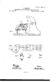
Be it known that I, OARLILE MASON, of the city of Chicago, Cook county, State of Illinois, have invented new and useful Improvements in Machines for Punching Metal Plates, of which the following is a full description, reference being had to the accompanying drawings, in which- Figure 1 is a side elevation; Fig. 2, a plan view; Fig. 3, an end view; Fig. 4, an enlarged elevation of that part of the machine which regulates the distance between the holes; Figs. 5, 6, and 7, details of some of the parts shown in Fig. 4.
The objects of this invention are to construct a machine which can be used in punching sheet-metal plates, by the use of a pivoted adjustable guide-bar and traveling guide combined with the table, as hereinaftermore fully described, and by means of peculiar devices for regulating the distance between the holes. The machine is so constructed that it can be used for punching holes in plates of diiferent widths.
In the drawings, A represents a stationary frame or bed; B, a frame resting upon ways a, and having a lateral movement. I) is a screw, by means of which the frame B is adjusted laterally. G is another frame, resting and moving upon the ways 0 upon the top of the frame B. D is a table, pivoted at the center to the frame 0. E is a guide-bar, having a groove in the upper side, as shown in Fig. 3. It is pivoted at cl to the frame B. e is a bell-crank lever, having one end projecting beyond the side of the frame B. The other end is pivoted to the frame B, and also to one end of the arm f. pivoted to the under side of the guide-bar E. g is a plate secured in a slot or opening in the side of the frame B. It is provided with holes to receive a pin, which passes through the lever 0 and this plate g. h is a traveling block, located in the groove in guide-bar E. It is provided with rollers 2', arranged to move upon the top of the guide E. j is a pin, which passes through a hole in the end of the table D, and into the top of the traveling block h. F is a bar located a little distance from the frame 0, supported by and secured to rods or bars G, which are permanently connected to one side ot' the frame (3. k are circular pieces of metal, each of which is permanently fastened The other end of this armfis upon one end of a pin, '0, which pins pass through and rotate in suitable holes in the bar F. To the other end of these pins 1; are permanently secured arms H, the lower ends of which are pivoted to the movable bar I.
J is a bar, pivoted to F at l, and to I at m.' The lower end of this bar J has a hole to receive a pin, and the bar I is enlarged and provided with corresponding holes n. 1' is a handle upon I.
The center circular piece of metal 70 is socured at its center to the pin '0; but all the remaining pieces k are eccentrically secured to the pins 11. Those upon the right hand of the central piece is are so arranged that the eccentric is below the center line, and those upon the left hand so that the eccentric is above the center line, and the eccentricity regularly increases from the center toward each end.
12 is a bar designed to pass between the circular pieces it. Its lower end is pivoted to some part of the machine, and its upper end, as represented, is pivoted to the bar 8, which slides in suitable guides. K is a punch-head. The punch is not represented.
The bar F might be located close to the frame (3, or the disks k might be pivoted directly in such frame.
The guide-bar E is pivoted to the frame B at a point the same distance from the center of the machine-such center being on a line with the punch-as the distance from the center of the table 0 to the pin j, so that when the center of the table is exactly opposite the punch the pin j is exactly over the pivotal point 61 of the guide-bar. If, then, the guidebar be located parallel with the frame B, the table D will move in a direct line, which position is adapted to the punching of holes in straight lines. If the guide-bar be thrown over to one side, as shown in Fig. 2, and the table D be placed in the position represented in the Same figure, the outer end of the table will be thrown inward, and the other end will be thrown outward. In this position the parts are adapted to the punching of holes in a curved line, because as the frame 0 travels over the ways 0, the forward end of the table, being pivoted in the traveling block h, moving in the guidebar IE, will carry the end of the pivoted table D over toward the punch,
and when the center of the table is on a line with the punch, the pinj being over the pivotal point d, the table will be parallel with the frame upon which itis pivoted. By the continued movement of the table the same end will be carried still farther over, and the holes punched during this movement will be in a curved line. This curved line will be either convex or concave, as the inner end of the guide-bar is thrown over either to the right or left.
It will be observed that the guide-bar E is pivoted midway between the two sides of the frame B, and that when thrown out of a straight line one end is to the right and the other to the left of this center.
The sheet to be punched is secured to the table D by means of dogs or clamps located in slots in the table. These parts are not shown, but are well known. The sheet to be punched is located so that its center is along the center line of the table, and by means of the screw 1) the position of the frame B and the parts above ,are so adjusted as to bring the edge of the sheet the proper distance under the punch. When the holes have been punched in one edge of the sheet the table D can be reversed and then carried back to the position represented in Fig. 2, and the holes punched in the opposite edge. The position of the guide-bar E is changed by means of the lever e. A number of plates, g, may be prepared with holes properly adjusted to place this bar E at any desired angle, and the proper plate 9 can be placed in the machine when a change is required in the angle. It will be better to use a number of these plates, rather than a single one with a large number of holes. The adjustable frame B might be advantageously used for some kinds of work with the frame 0 and a fixed table.
It is customary to make boilers and other tubes with tapered courses; and in such cases i the holes in one edge of the plate must be a little farther apart than those in the other, which is accomplished in my machine by the eccentric pieces 70 and the parts connected therewith.
-The distance between the holes is determined by the distance between the pieces 70,
and the bar 12, coming between these pieces 6, serves as a stop to limit the movement of the table after one hole has been punched, and preparatory to the punching ofanother. This stop 19 can beoperated automatically. When these pieces 70 and the parts connected there with are in the position represented in Fig. 4, the distance from the center of each piece Ir to the edge of the adjoining piece is uniform. Supposing this distance to be' two inches, the holes punched in the plate will be all two inches apart. Now, if it be required tomake the distance between the holes a little greater, this can be accomplished by turning the pieces k partially around, which can be done through-the parts H I J, bringing these pieces 10' and the parts connected therewith. into .the position represented by the dotted lines in Fig. 4, in which the distance between the pieces 70 gradually increases from the center each way as the result of their eccentricity. As has been stated, and as will be seen by reference to Fig. 4., this eccentricity increases regularly both to the right and to the left from the central piecek; and the distance between the holes can be made greater or less by turning the pieces It more or less.
I have represented only seven of these pieces 70, but actually use any practical number. I have used as many as sixty four.
If the piece k, adjoining the central piece, be placed upon the pin r, so as to be one-sixteenth of an inch from its center, the next one must be two-sixteenths from its center, andv the next three-sixteenths, and so on to the end.
The frame B may be moved by a rack and pinion. The frame 0, while the metal is being punched, is moved by means of a Weight in the usual manner, and returned by a crank and a rack and pinion.
Instead of arranging the disks 70 as shown, one of the end ones might be pivoted at its center, all the others being eccentrically pivoted, the eccentricity being upon the same side of the center; but in such case it would be necessary, when the sheet is turned, either to change its position slightly, or to change the position of the stop. Hence, the form shown is thebest.
I am aware that a guide-bar to receive a block or shoe has been used; but such bar has been pivoted at the center of the machine, and in such machine, when the holes are to be punched in a curved line, the sheet must be secured upon the table diagonally with great care, and the table with the sheet cannot be reversed; but after the holes have been punched in one edge the sheet must be removed and turned around before punching the holes .in the other edge.
What I claim as new, and desire to secure by Letters Patent, is as follows:
1. In amachine for punching sheet metal, the guide-bar E, pivoted at or near its center, and at a point some distance from a line drawn transversely across the machine in a line with the punch, as described, in combi nation with a reversible table, D, and traveling block h, substantially as and for the purpose set forth.
2. In a machine for punching sheet metal, the pivoted disks It, in combination with suitable devices for moving and holding the same, all constructed and operating substantially as specified.
' 3. In a machine for punching sheet metal, the framesB and O and table D, in com bination with the guidebar E, substantially as and for the purpose specified.
' GARLILE MASON.
' Witnesses:
E. A. WEs'r, 0. W. BOND.
Publications (1)
| Publication Number | Publication Date |
|---|---|
| US185117A true US185117A (en) | 1876-12-05 |
Family
ID=2254522
Family Applications (1)
| Application Number | Title | Priority Date | Filing Date |
|---|---|---|---|
| US185117D Expired - Lifetime US185117A (en) | Improvement in machines for punching metal plates |
Country Status (1)
| Country | Link |
|---|---|
| US (1) | US185117A (en) |
Cited By (1)
| Publication number | Priority date | Publication date | Assignee | Title |
|---|---|---|---|---|
| US3057240A (en) * | 1958-08-15 | 1962-10-09 | Wallace Supplies Mfg Company | Cut-off machine work clamp |
-
0
- US US185117D patent/US185117A/en not_active Expired - Lifetime
Cited By (1)
| Publication number | Priority date | Publication date | Assignee | Title |
|---|---|---|---|---|
| US3057240A (en) * | 1958-08-15 | 1962-10-09 | Wallace Supplies Mfg Company | Cut-off machine work clamp |
Similar Documents
| Publication | Publication Date | Title |
|---|---|---|
| US185117A (en) | Improvement in machines for punching metal plates | |
| US943806A (en) | Key-cutting machines. | |
| US2275688A (en) | Paper jogging apparatus for printing presses | |
| US172325A (en) | Improvement in machines for planing stereotype-plates | |
| US931220A (en) | Metal-shearing machine. | |
| US491187A (en) | Metal-bending machine | |
| US31169A (en) | Stave-machine | |
| US691428A (en) | Wood-cutting machine. | |
| US622189A (en) | Metal-bending machine | |
| US1122598A (en) | Sheet-metal cutter. | |
| US364635A (en) | Dovetailing-machine | |
| US490837A (en) | stockwell | |
| US445589A (en) | S h eet- metal- fold i ng machine | |
| US405310A (en) | Saw-table gage | |
| US945687A (en) | Graduated-spacing table. | |
| US117095A (en) | Improvement in machines for cutting oval tin bottoms | |
| US514607A (en) | William t | |
| US128194A (en) | Improvement in machines for cutting cloth | |
| US54564A (en) | Improved machine for combing bristles | |
| US145292A (en) | Improvement in machines for punching, splitting, and creasing bridles | |
| US138290A (en) | Improvement in stereotype-plate holders | |
| US345639A (en) | Squaring-shears | |
| US497980A (en) | Sawing-machine | |
| US1221881A (en) | Mechanism for feeding sheet metal to punching-machines. | |
| US146247A (en) | Improvement in machines for grinding rolls |