US1851160A - Resistor grid - Google Patents
Resistor grid Download PDFInfo
- Publication number
- US1851160A US1851160A US328274A US32827428A US1851160A US 1851160 A US1851160 A US 1851160A US 328274 A US328274 A US 328274A US 32827428 A US32827428 A US 32827428A US 1851160 A US1851160 A US 1851160A
- Authority
- US
- United States
- Prior art keywords
- resistor
- furnace
- grid
- hearth
- cross sectional
- Prior art date
- Legal status (The legal status is an assumption and is not a legal conclusion. Google has not performed a legal analysis and makes no representation as to the accuracy of the status listed.)
- Expired - Lifetime
Links
- 239000000463 material Substances 0.000 description 4
- 239000002184 metal Substances 0.000 description 4
- 238000010276 construction Methods 0.000 description 3
- 238000009825 accumulation Methods 0.000 description 1
- 238000005266 casting Methods 0.000 description 1
- 238000010438 heat treatment Methods 0.000 description 1
- 238000004519 manufacturing process Methods 0.000 description 1
- 239000011819 refractory material Substances 0.000 description 1
- 230000000284 resting effect Effects 0.000 description 1
Images


Classifications
-
- H—ELECTRICITY
- H05—ELECTRIC TECHNIQUES NOT OTHERWISE PROVIDED FOR
- H05B—ELECTRIC HEATING; ELECTRIC LIGHT SOURCES NOT OTHERWISE PROVIDED FOR; CIRCUIT ARRANGEMENTS FOR ELECTRIC LIGHT SOURCES, IN GENERAL
- H05B3/00—Ohmic-resistance heating
- H05B3/62—Heating elements specially adapted for furnaces
-
- F—MECHANICAL ENGINEERING; LIGHTING; HEATING; WEAPONS; BLASTING
- F27—FURNACES; KILNS; OVENS; RETORTS
- F27D—DETAILS OR ACCESSORIES OF FURNACES, KILNS, OVENS OR RETORTS, IN SO FAR AS THEY ARE OF KINDS OCCURRING IN MORE THAN ONE KIND OF FURNACE
- F27D11/00—Arrangement of elements for electric heating in or on furnaces
- F27D11/02—Ohmic resistance heating
Definitions
- the invention relates to metallic resistor ids of cast, rolled orforged construction r use in electric furnaces or kilns, and
- lhe object of the present improvement is to provide a metallic resistor grid having substantially the cross sectional shape of a letter Y, whereby a casting, or the like, of substantially uniform thickness may be produced.
- a further object of the improvement is to provide a cross sectional shape of resistor arranged to be located in the furnace in such position that the greater part of the heat rays are directed away from the adjacent furnace wall;
- a further object is to provide a grid having a relatively large surface in proportion to its cross sectional area, whereby efficient and rapid emission of heat may be secured.
- Another obj slot is to provide a grid having disposition of material so as to give strength for resisting distortion when the 'd is located in a horiaontal plane.
- a still further object is to provide a grid of this cross sectional shape adapted for use 49 beneath the hearth ofa furnace or kiln over which material or articles to be treated are continuously or intermittently moved, Whereby scale and the like falling from the hearth and striking upon the resistor grid will easily slide or drop therefrom and be deposited upon the door beneath the resistor, preventing danger of 'short-circuiting the same. 1
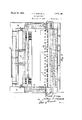
- Figure 1 is an elevation of a portion of the improved resistor grid especially adapted for use upon the side Walls of a furnace or kiln, or for use in the bottom of a furnane or kiln as illustrated in Fig. 3.
- FIG. 2 an enlarged cross sectional view through one leg of the grid taken substan tially on the line 2-2, Fig. l;
- FIG. 3 a vertical longitudinal section through a furnace provided with a roller hearth illustrating the manner of supportin the improved resistor grid beneath the heart rollers thereof;
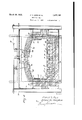
- Fig. 4 a transverse sectional view through a furnace provided with the resistor located beneath the hearth plates;
- FIG. 5 a fragmentary plan sectional view of the furnace illustrated in Fig. l, showing the improved resistor grid supported beneath the hearth plates thereof;
- FIG. 6 an enlarged fragmentary plan view of a portion of one of the hearth resistors and the supporting rod therefor;
- Fig. 7 a detached perspective view of the supporting rod
- Fig. 8 a detail sectional view through the cut-out portion of one of the grid supporting piers.
- the drawings show a furnace which may comprise the base 10, side Walls 11 and roof 12, formed of suitable refractory material and enclosed as by the metal casing 13.
- Structural members 14, of usual construction, may be provided for sup- 90 porting the brickwork and for carrying the roof supporting structure 15.
- the hearth may be formed of a spaced plurality of hearth rolls 1, spaced above the floor and adapted to convey material or articles to be treated, through the furnace from end to end, doors 2, being provided at each end for entrance and discharge of the material.
- a Each resistor grid 29 preferably includes a plurality of straight bars 29', spaced apart in the same plane and connected at alternate ends as by curved portions 29", so as to form a sinuous grid as best shown in Fig. 1.
- one or more of the improved resistors may be located below the hearth rollers, and spaced above the floor a of the furnace. 20
- the working hearth of the furnace shown" in Figs. 4 and 5 may be composed of the hearth plates 16 supported as upon the main and secondary piers 17 and 18 extended upward from the base or floor 10.
- one or more of the improved resistor grids may be located beneath the hearth plates and preferably spaced above the floor or base in order to prevent an accumulation of scale and the like upon the resistor.
- each of the secondary piers 18 may have spaced cut-out portions 19 extending to a point midwa between the hearth plates and the floor or ase.
- the resistor for use beneath the hearth is of the cross sectional shape shown in Fig. 2, in the form of an equilateral three-pointed star or Y comprising the three similar ribs 20, the angles between centers of the several ribs being each 120 degrees as shown.
- This bottom resistor may be of sinuous form and may comprise the alternate wide and narrow loop portions 21 and 22, respectively, the wide loops 21 being supported in the cut-out portions 19 of the secondary piers and the narrow loops 22 being located between said piers.
- the upper edges of the cut-out portions of the piers 18 may be beveled as shown at 23 so as to shed scale or the like which may fall from the hearth plates, thus preventing the scale from piling up upon the piers at this point and short-circuitlng the resistor.
- any suitable means may be provided for supporting the narrow loops 22, such as the rods 24 of suitable heat resisting metal, located between adjacent piers and having the upright prongs 25 between which the end portion of each loop 22 is received.
- Urrids of the same cross sectional shape may be supported from the roof as indicated generally at 26, resting upon the ledges 27 at opposite sides of the furnace and similar ledges upon the refractory blocks 28 which may be removably supported upon the under side of the roof.
- resistor grids may be mounted upon the side walls of the furnace as indicated generally at 29, one of these grids being shown in detail in Fig. 1 of the drawings. These grids may also be of sinuous shape and .adapted to be supported at their upper endsby any suitable form of hanger-or support carried by the side walls of the furnace.
- depending tail portions 30 may ,be formed at the lower ends of the loops and received in suitable guides as shown at 31,
- the resistor may be so positioned that one rib extends toward the interior of the furnace at substantially a right that this from the same and be deposited upon From the above, it will be evident that the improved grid may be cast, rolled, forged or otherwise formed of heat resisting metal with a substantially uniform cross sectional shape throughout and so arranged that the same is equally capable of use for hearth, roof or side wall heating.
- a resistor grid including a straight bar having a cross sectional shape in the form of a substantially equilateralthree-pointed star.
- a resistor grid including a straight bar having a cross sectional shape in the form of a substantially equilateral three-pointed star, the ribs thereof being of equal section.
- a resistor grid including a straight bar whose cross'section has three ribs of substantially equal section located at angles of 120 degrees to each other.
Landscapes
- Engineering & Computer Science (AREA)
- Mechanical Engineering (AREA)
- General Engineering & Computer Science (AREA)
- Tunnel Furnaces (AREA)
Description
March 29, 1932. COPE ET AL 851,369
RESISTOR GRID Filed Dec. 24, 1928 4 Sheets-Sheet l Fran/i 7. (*0 09 13 rlfiur Vang/2am RESISTOR GRID 1928 4 Sheets-Sheet 2 Filed Dec. 24
gwua ntow I Zia/z March 29, 1932. FT. COPE ET AL RESISTOR GRID Filed Dec. 24, 1928 4 Sheets-Sheet Patented Mar. 1932' UNITED STATES PATENT OFFICE Y FRANK '1. COPE AND ARTHUR H. VAUGHAN, O11" SALEM, OHIO, ASSIGNOBS TO THE ELEC- TRIO FURNACE COMPANY, OF SALEM, OHIO, A. CORPORATION OF OHIO RESISTOR GRID Application filed December 24, 1928. Serial No. 828,274.
The invention relates to metallic resistor ids of cast, rolled orforged construction r use in electric furnaces or kilns, and
more particularly to the cross sectional shape of such grids and the means for supportlng the same in the furnace or kiln.
It is well known that metallic resistor grids of diflerent cross sectional shapes have been made and used in electric furnaces andthe to like with various degrees of satisfaction and success. But, particularly where such resistors are cast, owing to the shrinkage of the heat resisting metal from which they are formed, and to the varying cross sectional g thickness of the grids, dificulties have been encountered in the manufacture and operation of such grids.
lhe object of the present improvement is to provide a metallic resistor grid having substantially the cross sectional shape of a letter Y, whereby a casting, or the like, of substantially uniform thickness may be produced.
A further object of the improvement is to provide a cross sectional shape of resistor arranged to be located in the furnace in such position that the greater part of the heat rays are directed away from the adjacent furnace wall;
A further object is to provide a grid having a relatively large surface in proportion to its cross sectional area, whereby efficient and rapid emission of heat may be secured.
Another obj slot is to provide a grid having eficient disposition of material so as to give strength for resisting distortion when the 'd is located in a horiaontal plane. A still further object is to provide a grid of this cross sectional shape adapted for use 49 beneath the hearth ofa furnace or kiln over which material or articles to be treated are continuously or intermittently moved, Whereby scale and the like falling from the hearth and striking upon the resistor grid will easily slide or drop therefrom and be deposited upon the door beneath the resistor, preventing danger of 'short-circuiting the same. 1
The above and other objects may be attained by constructing and mounting the improved resistor grid in the manner illustrated 1n the accompanying drawings, in which Figure 1 is an elevation of a portion of the improved resistor grid especially adapted for use upon the side Walls of a furnace or kiln, or for use in the bottom of a furnane or kiln as illustrated in Fig. 3.
Fig. 2, an enlarged cross sectional view through one leg of the grid taken substan tially on the line 2-2, Fig. l;
Fig. 3, a vertical longitudinal section through a furnace provided with a roller hearth illustrating the manner of supportin the improved resistor grid beneath the heart rollers thereof;
Fig. 4, a transverse sectional view through a furnace provided with the resistor located beneath the hearth plates;
Fig. 5, a fragmentary plan sectional view of the furnace illustrated in Fig. l, showing the improved resistor grid supported beneath the hearth plates thereof;
Fig. 6, an enlarged fragmentary plan view of a portion of one of the hearth resistors and the supporting rod therefor;
Fig. 7, a detached perspective view of the supporting rod; and
Fig. 8, a detail sectional view through the cut-out portion of one of the grid supporting piers.
Similar numerals refer to similar parts throughout the drawings.
For the purpose of illustrating the manner of mounting the improved resistor grid within a furnace or the like, the drawings show a furnace which may comprise the base 10, side Walls 11 and roof 12, formed of suitable refractory material and enclosed as by the metal casing 13. Structural members 14, of usual construction, may be provided for sup- 90 porting the brickwork and for carrying the roof supporting structure 15. y
In the furnace shown in Fig. 3, the hearth may be formed of a spaced plurality of hearth rolls 1, spaced above the floor and adapted to convey material or articles to be treated, through the furnace from end to end, doors 2, being provided at each end for entrance and discharge of the material. a Each resistor grid 29 preferably includes a plurality of straight bars 29', spaced apart in the same plane and connected at alternate ends as by curved portions 29", so as to form a sinuous grid as best shown in Fig. 1.
In order to produce the temperature necessary, one or more of the improved resistors, as shown at 29, may be located below the hearth rollers, and spaced above the floor a of the furnace. 20
The working hearth of the furnace shown" in Figs. 4 and 5 may be composed of the hearth plates 16 supported as upon the main and secondary piers 17 and 18 extended upward from the base or floor 10.
For the purpose of producing the desired temperature in the lower portion of the furnace one or more of the improved resistor grids may be located beneath the hearth plates and preferably spaced above the floor or base in order to prevent an accumulation of scale and the like upon the resistor.
With the construction of. piers above referred to, it will be seen that a space is left between the piers in which the resistor may be mounted. For this purpose each of the secondary piers 18 may have spaced cut-out portions 19 extending to a point midwa between the hearth plates and the floor or ase.
The resistor for use beneath the hearth is of the cross sectional shape shown in Fig. 2, in the form of an equilateral three-pointed star or Y comprising the three similar ribs 20, the angles between centers of the several ribs being each 120 degrees as shown.
This bottom resistor may be of sinuous form and may comprise the alternate wide and narrow loop portions 21 and 22, respectively, the wide loops 21 being supported in the cut-out portions 19 of the secondary piers and the narrow loops 22 being located between said piers.
The upper edges of the cut-out portions of the piers 18 may be beveled as shown at 23 so as to shed scale or the like which may fall from the hearth plates, thus preventing the scale from piling up upon the piers at this point and short-circuitlng the resistor.
Anysuitable means may be provided for supporting the narrow loops 22, such as the rods 24 of suitable heat resisting metal, located between adjacent piers and having the upright prongs 25 between which the end portion of each loop 22 is received.
The hearth resistor is thus supported midway between the floor and the hearth plates Urrids of the same cross sectional shape may be supported from the roof as indicated generally at 26, resting upon the ledges 27 at opposite sides of the furnace and similar ledges upon the refractory blocks 28 which may be removably supported upon the under side of the roof.
Similarly shaped resistor grids may be mounted upon the side walls of the furnace as indicated generally at 29, one of these grids being shown in detail in Fig. 1 of the drawings. These grids may also be of sinuous shape and .adapted to be supported at their upper endsby any suitable form of hanger-or support carried by the side walls of the furnace.
If desired, depending tail portions 30 may ,be formed at the lower ends of the loops and received in suitable guides as shown at 31,
. carried by the side walls.
In the side wall resistors, the same as in the other cases, the resistor may be so positioned that one rib extends toward the interior of the furnace at substantially a right that this from the same and be deposited upon From the above, it will be evident that the improved grid may be cast, rolled, forged or otherwise formed of heat resisting metal with a substantially uniform cross sectional shape throughout and so arranged that the same is equally capable of use for hearth, roof or side wall heating.
We claim:
1. A resistor grid including a straight bar having a cross sectional shape in the form of a substantially equilateralthree-pointed star.
2. A resistor grid including a straight bar having a cross sectional shape in the form of a substantially equilateral three-pointed star, the ribs thereof being of equal section.
3. A resistor grid including a straight bar whose cross'section has three ribs of substantially equal section located at angles of 120 degrees to each other.
4. A resistor grid including a straight bar whose cross section has three ribs of substan- 6. A resistor grid including a straight bar whose cross section has three similar ribs located at equal angles to each other whereby a large radiating surface, com ared with the cross sectional area, is obtaine In testimony that we claim the above, we
have hereunto subscribed our names.
FRANK T. COPE. ARTHUR H. VAUGHAN.
Priority Applications (1)
| Application Number | Priority Date | Filing Date | Title |
|---|---|---|---|
| US328274A US1851160A (en) | 1928-12-24 | 1928-12-24 | Resistor grid |
Applications Claiming Priority (1)
| Application Number | Priority Date | Filing Date | Title |
|---|---|---|---|
| US328274A US1851160A (en) | 1928-12-24 | 1928-12-24 | Resistor grid |
Publications (1)
| Publication Number | Publication Date |
|---|---|
| US1851160A true US1851160A (en) | 1932-03-29 |
Family
ID=23280273
Family Applications (1)
| Application Number | Title | Priority Date | Filing Date |
|---|---|---|---|
| US328274A Expired - Lifetime US1851160A (en) | 1928-12-24 | 1928-12-24 | Resistor grid |
Country Status (1)
| Country | Link |
|---|---|
| US (1) | US1851160A (en) |
Cited By (1)
| Publication number | Priority date | Publication date | Assignee | Title |
|---|---|---|---|---|
| US4649368A (en) * | 1985-06-03 | 1987-03-10 | National Element, Inc. | Electrical resistance heating element |
-
1928
- 1928-12-24 US US328274A patent/US1851160A/en not_active Expired - Lifetime
Cited By (1)
| Publication number | Priority date | Publication date | Assignee | Title |
|---|---|---|---|---|
| US4649368A (en) * | 1985-06-03 | 1987-03-10 | National Element, Inc. | Electrical resistance heating element |
Similar Documents
| Publication | Publication Date | Title |
|---|---|---|
| US1923644A (en) | Electric heating furnace | |
| US1963242A (en) | Supporting member for enameling racks | |
| US1851160A (en) | Resistor grid | |
| US2526359A (en) | Apparatus for bending glass sheets | |
| US1842972A (en) | Electrical furnace resistor | |
| US2159183A (en) | Self-baking electrode | |
| US3637912A (en) | Furnace for glass processes | |
| DE460763C (en) | Firebox ceiling with stones suspended from beams | |
| US1569444A (en) | Annealing furnace | |
| US1624217A (en) | Electric furnace | |
| US1767172A (en) | Resistor grid and method of supporting same | |
| US1897911A (en) | Heat treating furnace | |
| USRE17388E (en) | Electric furnace | |
| US1767171A (en) | Resistor grid | |
| US1690273A (en) | Electric furnace | |
| US2507076A (en) | Tunnel kiln | |
| US1661842A (en) | Electric furnace | |
| US1858489A (en) | Furnace construction | |
| US1686386A (en) | Furnace-roof construction | |
| US3061295A (en) | Open hearth furnace | |
| US2007605A (en) | Electric furnace | |
| US1444939A (en) | Electric furnace | |
| US1873239A (en) | Conveyer furnace | |
| US1813085A (en) | Ware support | |
| US1728752A (en) | Electric heating unit |