US1851156A - Bark removing machine - Google Patents
Bark removing machine Download PDFInfo
- Publication number
- US1851156A US1851156A US293432A US29343228A US1851156A US 1851156 A US1851156 A US 1851156A US 293432 A US293432 A US 293432A US 29343228 A US29343228 A US 29343228A US 1851156 A US1851156 A US 1851156A
- Authority
- US
- United States
- Prior art keywords
- frame
- cutter
- pieces
- wood
- bark
- Prior art date
- Legal status (The legal status is an assumption and is not a legal conclusion. Google has not performed a legal analysis and makes no representation as to the accuracy of the status listed.)
- Expired - Lifetime
Links
- 239000002023 wood Substances 0.000 description 17
- 238000010276 construction Methods 0.000 description 5
- 230000000717 retained effect Effects 0.000 description 2
- 239000011435 rock Substances 0.000 description 2
- 229920001131 Pulp (paper) Polymers 0.000 description 1
- 230000001419 dependent effect Effects 0.000 description 1
- JXSJBGJIGXNWCI-UHFFFAOYSA-N diethyl 2-[(dimethoxyphosphorothioyl)thio]succinate Chemical compound CCOC(=O)CC(SP(=S)(OC)OC)C(=O)OCC JXSJBGJIGXNWCI-UHFFFAOYSA-N 0.000 description 1
- 230000000694 effects Effects 0.000 description 1
- 230000001788 irregular Effects 0.000 description 1
- 229940061319 ovide Drugs 0.000 description 1
- 229920000136 polysorbate Polymers 0.000 description 1
- 238000009966 trimming Methods 0.000 description 1
- 239000002699 waste material Substances 0.000 description 1
Images

Classifications
-
- B—PERFORMING OPERATIONS; TRANSPORTING
- B27—WORKING OR PRESERVING WOOD OR SIMILAR MATERIAL; NAILING OR STAPLING MACHINES IN GENERAL
- B27L—REMOVING BARK OR VESTIGES OF BRANCHES; SPLITTING WOOD; MANUFACTURE OF VENEER, WOODEN STICKS, WOOD SHAVINGS, WOOD FIBRES OR WOOD POWDER
- B27L1/00—Debarking or removing vestiges of branches from trees or logs; Machines therefor
- B27L1/10—Debarking or removing vestiges of branches from trees or logs; Machines therefor using rotatable tools
Definitions
- This invention relates -'to machines lfor re'- movlng bark from wood andparticularly to machines.
- :provij sion is: made for advancing the pieces of wood from which /barkisto beremovedacross a table against a cutterfand ⁇ wherein the cutter, or bark removing felement,r "is adjustableto permit a. desired 'operationon pieces 'of various size and shape-y as #they are conveyed ⁇ past it. .Y
- Vthe invention -resides in the provision of' a power driven bark heights, and wherein thev carrier'is pivotally removing machine, embodying a revolving cutter head whiehlsfmounted on a carrier which in turn is supported in a frame that is verticallyladjustable so as to provide for bodily raising and lowering the cutter and its ⁇ carrier to'suit pieces of wood ot various mounted inthe vertically' adjustable frame sothat the 'cutterlmay be tilted to any? suitable degree in accordance with the curvature l or slope of the surface ⁇ from which the bark is to be removed.
- V f Y W k Figure 3 is a cross sectional view taken substantially on the line 3,-3 in Figure 1 and illustrating theY up and down pivotal movef ment of the ycutter carrier andthe vertical adjustment of the carrier support in the main ⁇ frame.
- Figure 4 is a crossk section4 on the linea-ly inl Figure l.
- f f yReferring more in detail to the drawingsl designates what may bea" horizontal table or base on which the wood barking-machine 1s mounted and which is provided longitudiiially along one side with a groove, or guide A guide railfG is fixed :to tleptable parallel.
- l These franiesare parallel and in spaced" relation and Abetween them
- Vthere 1s mounted a vertically adjustable -rameor carrier by meansof which the cutter andl its driving motor 'areJ supported.V 4
- carrier comprises opposite side edges slidalblyk contained in a5 verticalif Vend plateslOilOf which -havetheir"opposite 9-92
- Adjustment of the outer end of the lever upwardly or downwardly will effect vertical adjustment of the movable frame and any desired adj ustment may be retained by engaging a latch bolt 21 carried by the lever 15 with the notches 22 of a segment 23 that is fixed to the end frame 9 concentrically with respect to the shaft 16.
- the bolt 21 is here shown as slidably carried by a supporting bracket 24 fixed to the lever and is urged inwardly to locking position by pressure of a coiled spring 25, but it may be disengaged from the segment to permit a change of adjustment by pressure against a grip piece 26 that is pivotally attached to the lever adjacent the handle portion, and connected to the bolt by means of a rod or wire 27.
- a base plate 32 Formed integral with, or otherwise attached to the frame 30, is a base plate 32 on which an electric motor 33 is securely mounted so that its shaft 34 will extend at a right angle to the direction of travel of the conveyer and directly across the path of the pieces of wood delivered thereby, as shown best in Figures 1 and 3.
- the shaft is shown to be extended through a bar 35 formed in the frame 30 so as to steady the motor, and fixed on the outer end of the shaft, is the bark removing cutter 36 which, preferably, is of a cylindrical form with its surface concaved and provided with suitable cutting knives, ribs or burrs extending lengthwise thereof.
- the cutter is supported directly above the path of travel of the piece advanced by the conveyer and, by adjustment of the pivotally mounted carrier frame and suitable adjustment of the vertically movable frame, may be disposed in various positions to best suit pieces of various thickness and curvature.
- the adjusting lever 40 which is rigidly fixed to the frame 30 to extend laterally, as does the lever 15, across but substantially above the conveyer.
- This lever is equipped with a locking bolt 41 adapted to be engaged with notches of a plate segment 43 attached to the end plate 10.
- the bolt is yieldably held in locking position by a coiled spring 44 bearing against it and it may be released by the pressure against a grip plate 45 mounted at the end of the lever and connected to the bolt by a rod or wire 46.
- gauge devices and 51 which are in the form of graduated scales, and are fixed vertically to the base 1 adjacent opposite sides of the path along which the pieces are advanced to the machine. These scales are graduated vertically in inches so that, as a piece of wood is delivered between them, its height or thickness at both the inner and outer edges may be determined.
- a column 54 graduated in inches and, fixed to the end plate 10 ofthe vertically adjustable frame, is a pointer 55 adapted to follow along the vertical column 54.
- the position to which the vertically adjustable frame should be adjusted to suit any piece of wood is dependentupon the thickness of the piece, which the operator may determine by watching it as it passes the scale 50. He then adjusts the frame vertically by manipulation of the lever 15 until the pointer 55 coincides with the number in the column 54 which is the same as the thickness of the piece in inches.
- the slope or inclination to which the cutter should be adjusted is dependent upon the eurvature or slope of the piece of wood from which bark is to be taken, as shown by the scales 50 and 51, and proper adjustment is made by reference to graduations, as at 60, which I have provided on an arcuate surface 61 of the frame 30; this surface being formed concentrically about the trunnion 31 with a pointer 62 fixed to the end plate 10 and terminating adjacent the arcuate surface.
- ybark may be removed from'pieces of various thickness and slope with a minimum kloss of wood.
- the vertical adjustment provides for raising and lowering the cutter to accommo-k date pieces of various thickness, asmeasured i on the scale 50, while the pivoted frame 'perporting frames.
- gauge devices for indicating the thickness and slope of each piece delivered along the guideway, means for adjusting the cutter head vertically and axially to suit each piece and indicating means on the adjustable supports for determining when these adjust-l mentsk correspondto readings taken from the 'A thickness andslope indicating gauges.
- a guideway means for advanc- 'Y ing wood pieces along the guideway, gauge devices at opposite sides of the guideway for indicating the thickness of the pieces at-their inner andouter edges, a base frame'ixedadjacent the guideway, asecond frame vertiv callyadjustable therein, a third frame pivotallymounted in the second frame to rock'on an axis parallel to the guideway, a cutter head mounted on the pivoted frame to overlie the guideway and operable to remove bark from pieces delivered therealong; said cutter vbeing disposedwith its axis transversely to the guideway, means for raisingor lowering the verticallyfadjustable frame, means for adjusting the kpivoted frame and graduated scales onL the base frame and on a supporting member orthe pivoted frame cooperating f with pointers xedito the adjustable parts whereby their positions of adjustment may be J made to correspond with readings on the gaugeV devices adjacent the guideway.l
Landscapes
- Life Sciences & Earth Sciences (AREA)
- Engineering & Computer Science (AREA)
- Wood Science & Technology (AREA)
- Forests & Forestry (AREA)
- Debarking, Splitting, And Disintegration Of Timber (AREA)
- Manufacture Of Wood Veneers (AREA)
- Apparatuses For Bulk Treatment Of Fruits And Vegetables And Apparatuses For Preparing Feeds (AREA)
Description
'DE LoNA CALAHAN BARK REMOVING MACHINE Filed July 1v, 1928 ATL-m March 2.9, 1932.
INVENTOR DE I ONA CALAHAN 4- ATTORNEY March 29, 1932. DE LONA CALAHAN 1,851,156v
BARK REMOVING MACHINE ATTORNEY Patented` Mar. 29,- 1932i:
DE term cAtAnAN, on rnfrnrnx; yiivasianti'exilioN c BAnnnnMevINGyfnAenrivnf Y `'Applicat-imi mea July 17,
This invention relates -'to machines lfor re'- movlng bark from wood andparticularly to machines. for that purpose 1n which :provij sion is: made for advancing the pieces of wood from which /barkisto beremovedacross a table against a cutterfand` wherein the cutter, or bark removing felement,r "is adjustableto permit a. desired 'operationon pieces 'of various size and shape-y as #they are conveyed` past it. .Y
It is the principal-'obj ect ot' the present invention to providefabark removing machine ofv the'above stated character that is especially designedjfor operation :on short, kwaste pieces-oit wood of irregular sizef'and shape andl particularly for the removal of bark from slab wood or `pieces which, for. various reason`sare not desirable or suitable for sale ascommercial lumber but which are suitable and-desirable for paper pulp: Y
More specically stated, Vthe invention -resides in the provision of' a power driven bark heights, and wherein thev carrier'is pivotally removing machine, embodying a revolving cutter head whiehlsfmounted on a carrier which in turn is supported in a frame that is verticallyladjustable so as to provide for bodily raising and lowering the cutter and its `carrier to'suit pieces of wood ot various mounted inthe vertically' adjustable frame sothat the 'cutterlmay be tilted to any? suitable degree in accordance with the curvature l or slope of the surface `from which the bark is to be removed. l ,Y Y u Itis also an object of the invention to pro-rrr vide gauging devices adjacent the'path along Y which the pieces to bebarked are delivered'y y' to the machine whereby the operator may determine the positions toy whichy the` parts should be adjusted for any particular piece,
and also :tofpr'ovide easily operable means for e'ii'e'cting andretaining the desired adjustments. L Y 1 Y,
Other objects ofthe-invention reside inthe various details' Lof construction and in the. combination of parts and inr their modefof operation, as y*will hereinafter'bedescribed;
In accomplishing ythese andy other objects of the inventio'nflfhave 4provided the iin.V
proved detailsv of constructiom the :preferred:
1928. se'rii No; 293,432. n
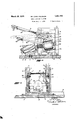
forms of. which are illustrated -in the ,accompanying drawings,` wherein Y l' Figure l' is a plan view of a bark removl ing machine made in accordance with the present invention. A
lFigure 2 isa side elevation of the ma-` chine."V f Y W kFigure 3 isa cross sectional view taken substantially on the line 3,-3 in Figure 1 and illustrating theY up and down pivotal movef ment of the ycutter carrier andthe vertical adjustment of the carrier support in the main` frame. Y
Figure 4 is a crossk section4 on the linea-ly inlFigure l. f f yReferring more in detail to the drawingsl designates what may bea" horizontal table or base on which the wood barking-machine 1s mounted and which is provided longitudiiially along one side with a groove, or guide A guide railfG is fixed :to tleptable parallel.
with the line of travel of the conveyercin such manner as to' serve; asa means whereby the pieces will bev yguided in their travel and properly positioned with respect tothe 'bark removing cutter',r presently described.
Located alongside A of the conveyer guide-V way and fixedt'o th'e'table, or base,`1, is a rigid frame structure/comprising a base plate 8 with opposite end :trames` 9&9. l These franiesare parallel and in spaced" relation and Abetween them Vthere 1s mounted a vertically adjustable -rameor carrier by meansof which the cutter andl its driving motor 'areJ supported.V 4 This. carrier comprises opposite side edges slidalblyk contained in a5 verticalif Vend plateslOilOf which -havetheir"opposite 9-92 The twoplatesarerigidlyjoinedand c braced byca` cross bar 1B thatie'Xtends bef;
tween their lower ends andv which is securelyy bolted thereto. y f f Theltramejembodied Iby the twoend plates' 1010 and the cross bar 13, is vertically adjustable in the main frame by means f a lever 15 which is keyed on a rock shaft 16 which extends between and is pivotally supported by the end frames 9 9. Fixed to the shaft 16, are inwardly extending arms 17-17 which lie adjacent the inner sides of the plates -10 and which are provided, at their ends, with rollers 18 supported in horizontal slots 19 in the plates. Adjustment of the outer end of the lever upwardly or downwardly will effect vertical adjustment of the movable frame and any desired adj ustment may be retained by engaging a latch bolt 21 carried by the lever 15 with the notches 22 of a segment 23 that is fixed to the end frame 9 concentrically with respect to the shaft 16. The bolt 21 is here shown as slidably carried by a supporting bracket 24 fixed to the lever and is urged inwardly to locking position by pressure of a coiled spring 25, but it may be disengaged from the segment to permit a change of adjustment by pressure against a grip piece 26 that is pivotally attached to the lever adjacent the handle portion, and connected to the bolt by means of a rod or wire 27.
Pivotally mounted within the vertically adjustable frame, is a motor and cutter supporting carrier, or frame, 30, of rectangular form provided at its opposite ends with trunnions 31-31 which are pivotally mounted in the end plates 10-10.
Formed integral with, or otherwise attached to the frame 30, is a base plate 32 on which an electric motor 33 is securely mounted so that its shaft 34 will extend at a right angle to the direction of travel of the conveyer and directly across the path of the pieces of wood delivered thereby, as shown best in Figures 1 and 3. In the present construction, the shaft is shown to be extended through a bar 35 formed in the frame 30 so as to steady the motor, and fixed on the outer end of the shaft, is the bark removing cutter 36 which, preferably, is of a cylindrical form with its surface concaved and provided with suitable cutting knives, ribs or burrs extending lengthwise thereof. The cutter is supported directly above the path of travel of the piece advanced by the conveyer and, by adjustment of the pivotally mounted carrier frame and suitable adjustment of the vertically movable frame, may be disposed in various positions to best suit pieces of various thickness and curvature.
As a means of adjusting the pivoted carrier to the different positions required and for holding it at any position of adjustment, I haveprovided the adjusting lever 40 which is rigidly fixed to the frame 30 to extend laterally, as does the lever 15, across but substantially above the conveyer. This lever is equipped with a locking bolt 41 adapted to be engaged with notches of a plate segment 43 attached to the end plate 10. The bolt is yieldably held in locking position by a coiled spring 44 bearing against it and it may be released by the pressure against a grip plate 45 mounted at the end of the lever and connected to the bolt by a rod or wire 46.
With the parts so arranged, it is possible to raise and lower the motor and cutter body in accordance with the width or thickness of the piece to be operated on, and also it is possible to tilt the cutter to cause its trimming surface to coincide with the curvature of the surface from which bark is to be out, so that there will be no appreciable waste of wood.
In order that the operator may accurately determine the positions to which the parts should be adjusted for each particular piece of wood as it is delivered to the cutter, I have provided the gauge devices and 51, which are in the form of graduated scales, and are fixed vertically to the base 1 adjacent opposite sides of the path along which the pieces are advanced to the machine. These scales are graduated vertically in inches so that, as a piece of wood is delivered between them, its height or thickness at both the inner and outer edges may be determined. Also, on the outer face of the frame 9, as shown in Figure 2, is a column 54 graduated in inches and, fixed to the end plate 10 ofthe vertically adjustable frame, is a pointer 55 adapted to follow along the vertical column 54. The position to which the vertically adjustable frame should be adjusted to suit any piece of wood is dependentupon the thickness of the piece, which the operator may determine by watching it as it passes the scale 50. He then adjusts the frame vertically by manipulation of the lever 15 until the pointer 55 coincides with the number in the column 54 which is the same as the thickness of the piece in inches.
The slope or inclination to which the cutter should be adjusted is dependent upon the eurvature or slope of the piece of wood from which bark is to be taken, as shown by the scales 50 and 51, and proper adjustment is made by reference to graduations, as at 60, which I have provided on an arcuate surface 61 of the frame 30; this surface being formed concentrically about the trunnion 31 with a pointer 62 fixed to the end plate 10 and terminating adjacent the arcuate surface. ln operation of the machine, the operator reads the thickness of each piece at its inner and outer edges as it is delivered to the machine past the scales 50 and 51; he then adjusts the vertical frame by means of the lever 15 in accordance with the reading on the scale 50. He then adjusts the pivoted frame in accordance with the reading on the scale 51, that is, if the thickness of the piece should be shown to be 6 inches at the inside and 3 inches at the outside, he adjusts the vertically movable frame to the 6 inch mark, as indicated by the amarga position of the pointer 55, with :respect toV As a means of holding the pieces steadyv While passing beneath the cutter, l have providedV a frame 7 O supported from the motor shaft and held against rotation by connection Y with the frame 30. This frame 70 encircles the cutter and, at opposite sides of the cutter, hasmounted therein rollers 7l and 72 adapted to roll upon the pieces delivered to the` cutter. The rollers 71 and-72 have trunnions at their ends mounted in bearings` which are slidably mounted in grooves T4 in their supporting frame structure, with springs 7 5.
pressing against the bearings to urge the rollers downwardly.
Assuming the device to be soV constructed,
j it is readily apparent that the conveyer will suit each particular piece as it is .delivered to opera-te to bring the pieces of wood in rapid succession to the revolving cutterhead vand that lthe operator may readily determine the positions to which the vertically movable and pivoted frames kshould be adjusted to best the cutter. It is also apparent that byproviding a machine fof this character, wherein the cutter maybe vertically adjusted as well as tilted to various inclined positions, the
ybark may be removed from'pieces of various thickness and slope with a minimum kloss of wood. The vertical adjustment provides for raising and lowering the cutter to accommo-k date pieces of various thickness, asmeasured i on the scale 50, while the pivoted frame 'perporting frames.
` vby Letters Patent, is: I o
l. A machineoithe character described,Vr
mitstilting 'of the cutter so that the ycutting' surface will correspond to surfaces of varyingslope as determined by the reading of the scale 51 in connection with the reading otithe scale 50. VIt is readily apparent that various details of construction and combination of parts. Vco'uldbe altered without departing from the spirit of the invention and, for this reason, I do not wish to be limited only to the construction as herein illustrated since the nov- Y elty of the invention isthought to reside in fy the construction which provides for both vertical and pivotal movement ofr'thecutter sup-k lla'ving thus described my invention, what I'vclainu as newtherein and desire to secure' ly with Vthe bark surfaces thereof exposed, a
comprising vin combination, a guideway, a
conveyer 'means for advancing wnod pieces along-the guideway, a base frame structure. "t mounted adjacent the 'guideway, a second framevertcally adjestable' inthey basen-amai f athirtillframepiwotallysupportedy withinithe second frameto rockionan.axisthatlisdorie zf'on'tal' and' paralleli-to*theguideway, ai'notor. mounted oni the pivoted tramef having;*its v drive shaft extended injapl'aneat Ii-ght` angles tol* .the direction et the 'gui'dewa`y5 afcutter head on saidshaft operable" to remove'barkf from piecesotwood'moved.V along the guideway, a lever fixed to the pivoted frame whereby it may be pivotally adjustedto change the. inclination of the cutter lwith respect to the vguideway, a releasable lock on said lever whereby the adjustment may be retained, an adjusting lever pivotally mounted on the base frame and operatively connected to the ver tically adjustable frame and a releasable lock carried thereby whereby it may be held Lat diiferent positions of adjustment.
2. In a machine of the character described,
in combination with a guideway along which v wood pieces may be advanced and a cutter head mountedtransversely with respect to the direction of travel of said pieces and having an ,adjustable support `whereby the cutter may be raised or lowered and also axially tilted, of gauge devices for indicating the thickness and slope of each piece delivered along the guideway, means for adjusting the cutter head vertically and axially to suit each piece and indicating means on the adjustable supports for determining when these adjust-l mentsk correspondto readings taken from the 'A thickness andslope indicating gauges.
3. A machine of the character described, in
combination, a guideway, means for advanc- 'Y ing wood pieces along the guideway, gauge devices at opposite sides of the guideway for indicating the thickness of the pieces at-their inner andouter edges, a base frame'ixedadjacent the guideway, asecond frame vertiv callyadjustable therein, a third frame pivotallymounted in the second frame to rock'on an axis parallel to the guideway, a cutter head mounted on the pivoted frame to overlie the guideway and operable to remove bark from pieces delivered therealong; said cutter vbeing disposedwith its axis transversely to the guideway, means for raisingor lowering the verticallyfadjustable frame, means for adjusting the kpivoted frame and graduated scales onL the base frame and on a supporting member orthe pivoted frame cooperating f with pointers xedito the adjustable parts whereby their positions of adjustment may be J made to correspond with readings on the gaugeV devices adjacent the guideway.l
4, In combination,v a conveyer by which` slab wood pieces may be advanced successives framevstructure mounted adjacent the con;
veyer,l a cutter supporting v`frame* vertically adjustable in the said frame structure, ,a
motor driven shaft mounted on said adjustin a vertical plane transversely of the conveyer and a cutter head mounted on the said shaft and adapted by adjustment of the frame to be brought against the slabs to remove the bark therefrom as they are successively ad-v vanced by the conveyer.
Signed at Fairfax, Washington, this 30th day of June, 1928.
DE LONA CALAHAN.
Priority Applications (1)
| Application Number | Priority Date | Filing Date | Title |
|---|---|---|---|
| US293432A US1851156A (en) | 1928-07-17 | 1928-07-17 | Bark removing machine |
Applications Claiming Priority (1)
| Application Number | Priority Date | Filing Date | Title |
|---|---|---|---|
| US293432A US1851156A (en) | 1928-07-17 | 1928-07-17 | Bark removing machine |
Publications (1)
| Publication Number | Publication Date |
|---|---|
| US1851156A true US1851156A (en) | 1932-03-29 |
Family
ID=23129057
Family Applications (1)
| Application Number | Title | Priority Date | Filing Date |
|---|---|---|---|
| US293432A Expired - Lifetime US1851156A (en) | 1928-07-17 | 1928-07-17 | Bark removing machine |
Country Status (1)
| Country | Link |
|---|---|
| US (1) | US1851156A (en) |
Cited By (5)
| Publication number | Priority date | Publication date | Assignee | Title |
|---|---|---|---|---|
| US2899993A (en) * | 1959-08-18 | Slab-rossing machine | ||
| US2979123A (en) * | 1956-11-05 | 1961-04-11 | Cleveland Trust Co | Tire buffing machine |
| US3319673A (en) * | 1964-05-15 | 1967-05-16 | Hombak Maschinenfab Kg | Machine for producing wood chips |
| US5954105A (en) * | 1996-05-24 | 1999-09-21 | Smith; Dennis William | Workhead for timber processing |
| US5957177A (en) * | 1995-05-25 | 1999-09-28 | Smith; Dennis William | Coupled workhead for use in timber processing |
-
1928
- 1928-07-17 US US293432A patent/US1851156A/en not_active Expired - Lifetime
Cited By (5)
| Publication number | Priority date | Publication date | Assignee | Title |
|---|---|---|---|---|
| US2899993A (en) * | 1959-08-18 | Slab-rossing machine | ||
| US2979123A (en) * | 1956-11-05 | 1961-04-11 | Cleveland Trust Co | Tire buffing machine |
| US3319673A (en) * | 1964-05-15 | 1967-05-16 | Hombak Maschinenfab Kg | Machine for producing wood chips |
| US5957177A (en) * | 1995-05-25 | 1999-09-28 | Smith; Dennis William | Coupled workhead for use in timber processing |
| US5954105A (en) * | 1996-05-24 | 1999-09-21 | Smith; Dennis William | Workhead for timber processing |
Similar Documents
| Publication | Publication Date | Title |
|---|---|---|
| US2299262A (en) | Power-driven bench saw | |
| US1851156A (en) | Bark removing machine | |
| US3935776A (en) | Paper cutting machine | |
| US1644961A (en) | Splitting machine | |
| US946635A (en) | Machine for grinding straight machine-knives. | |
| US2399822A (en) | Gang ripsaw | |
| US2342267A (en) | Bowling alley leveling machine | |
| US611599A (en) | Metal cutter and roller | |
| US2930123A (en) | Bevel cutting machine | |
| US962047A (en) | Planer-knife sharpener. | |
| US1724042A (en) | Sawing machine | |
| US1159795A (en) | Tie-gaining machine. | |
| US930744A (en) | Paper-trimming machine. | |
| US310534A (en) | Samuel j | |
| US619397A (en) | Cutter | |
| US1342992A (en) | Measuring instrument | |
| USRE10652E (en) | Perforating-machine | |
| US1769602A (en) | Paper-trimming machine | |
| US1740111A (en) | Candy-cutting machine | |
| US972101A (en) | Cage-table. | |
| SU33274A1 (en) | Motor plane for planing floors, decks, etc. | |
| US1545544A (en) | Machine for copying shoe lasts and other irregular bodies | |
| US122674A (en) | Improvement in machines for chamfering the rails of wagon-bodies | |
| US318101A (en) | Caramel-cutter | |
| US24240A (en) | Sawing-machine for resawing boards |