US1851150A - Gas stove burner-bar and slide-plate support - Google Patents
Gas stove burner-bar and slide-plate support Download PDFInfo
- Publication number
- US1851150A US1851150A US461242A US46124230A US1851150A US 1851150 A US1851150 A US 1851150A US 461242 A US461242 A US 461242A US 46124230 A US46124230 A US 46124230A US 1851150 A US1851150 A US 1851150A
- Authority
- US
- United States
- Prior art keywords
- burner
- bar
- compartment
- socket
- wall
- Prior art date
- Legal status (The legal status is an assumption and is not a legal conclusion. Google has not performed a legal analysis and makes no representation as to the accuracy of the status listed.)
- Expired - Lifetime
Links
- 239000007789 gas Substances 0.000 description 24
- 238000010276 construction Methods 0.000 description 15
- 125000006850 spacer group Chemical group 0.000 description 4
- XEEYBQQBJWHFJM-UHFFFAOYSA-N Iron Chemical compound [Fe] XEEYBQQBJWHFJM-UHFFFAOYSA-N 0.000 description 2
- 239000004576 sand Substances 0.000 description 2
- 238000010792 warming Methods 0.000 description 2
- 229910001018 Cast iron Inorganic materials 0.000 description 1
- 241001417495 Serranidae Species 0.000 description 1
- 229910000831 Steel Inorganic materials 0.000 description 1
- 241000953561 Toia Species 0.000 description 1
- 238000009835 boiling Methods 0.000 description 1
- 238000005266 casting Methods 0.000 description 1
- 238000010411 cooking Methods 0.000 description 1
- 210000003298 dental enamel Anatomy 0.000 description 1
- 238000006073 displacement reaction Methods 0.000 description 1
- 239000002737 fuel gas Substances 0.000 description 1
- ASTNLROMDNGJLS-UHFFFAOYSA-N hot-7 Chemical compound CCCSC1=CC(OC)=C(CCNO)C=C1OC ASTNLROMDNGJLS-UHFFFAOYSA-N 0.000 description 1
- 238000009413 insulation Methods 0.000 description 1
- 229910052742 iron Inorganic materials 0.000 description 1
- 210000003141 lower extremity Anatomy 0.000 description 1
- 238000003754 machining Methods 0.000 description 1
- 238000004519 manufacturing process Methods 0.000 description 1
- 239000000463 material Substances 0.000 description 1
- 239000002184 metal Substances 0.000 description 1
- 229910052751 metal Inorganic materials 0.000 description 1
- 230000008520 organization Effects 0.000 description 1
- 239000002245 particle Substances 0.000 description 1
- 230000002093 peripheral effect Effects 0.000 description 1
- 230000001172 regenerating effect Effects 0.000 description 1
- 230000000717 retained effect Effects 0.000 description 1
- 238000007665 sagging Methods 0.000 description 1
- 239000007787 solid Substances 0.000 description 1
- 239000010959 steel Substances 0.000 description 1
- 239000000126 substance Substances 0.000 description 1
Images
Classifications
-
- F—MECHANICAL ENGINEERING; LIGHTING; HEATING; WEAPONS; BLASTING
- F24—HEATING; RANGES; VENTILATING
- F24C—DOMESTIC STOVES OR RANGES ; DETAILS OF DOMESTIC STOVES OR RANGES, OF GENERAL APPLICATION
- F24C15/00—Details
- F24C15/16—Shelves, racks or trays inside ovens; Supports therefor
Definitions
- Said outer end of said burner bar 16 is caused to be positively retained within said semi-socket 31 by means of a bracket-shaped clamp or cleat 32 whose vertical flange 33 has a single cored hole 3% which is adapted to he slipped over the outer end of the bolt 27.
- a bracket-shaped clamp or cleat 32 whose vertical flange 33 has a single cored hole 3% which is adapted to he slipped over the outer end of the bolt 27.
- This object is accomplished by the provision of a pair of centering flanges 36-36 which, when said cleat is in proper position, embrace opposite sides of the peripheral face of the semi-socket 31 and thereby center the cleat properly and prevent any displacement thereof after the nut 35 has been screwed tight.
- This cleat 32 together with the semipocket 31 constitutes what may be termed a split pocket to distinguish the same from the annular retaining pocket 18.
- These centering flanges 36 of the cleat 32 extend over and some distance beyond the side walls of their companion semi-socket 31 and thereby constitute a cover for the same whereby particles of scale and dirt are prevented from dropping into the space between the periphery of the burner bar 16 and the inner faces of the semi-socket 31.
- each of the secondary hangers 30 is provided with an integral spacer leg40 which projects horizontally outward from the main body of said hanger and bears with its outer face against the inner face of the outer wall 25 of the burner compartment.
- an integral spacer leg40 which projects horizontally outward from the main body of said hanger and bears with its outer face against the inner face of the outer wall 25 of the burner compartment.
- the combined length of the spacer leg 40 plus the length of the bracket 411 of the secondary hanger 30 is greater than the length ofthe bracket 41 of the primary hanger 20.
- a gas stove comprising a burner compartment; a plurality of hangers arranged at the front and rear ends of sai d compartment, each having a socket; a plurality of burner bars having their ends receivable within said sockets; a single slide plate secured adjacent its opposite ends to said hangers and having a guide flange; a drawer hearing against said guide flange; and gas burners mounted on said burner bars.
Landscapes
- Engineering & Computer Science (AREA)
- Chemical & Material Sciences (AREA)
- Combustion & Propulsion (AREA)
- Mechanical Engineering (AREA)
- General Engineering & Computer Science (AREA)
- Gas Burners (AREA)
Description
March 29, 1932. BRElTWlESER 1,851,150
GAS STOVE BURNER BAR AND SLIDE PLATE SUPPORT Filed June 14. 1930 5 Sheets-Sheet l "III" III" I Il March 29, 1932. BREITWESER 1,851,150
GAS STOVE BURNER BAR AND SLIDE PLATE SUPPORT Filed June 14, 1930 3 Sheets-Sheet 2 75 7& 13
March 29,1932- E. BREITWIESER 1,851,150
GAS STOVE BURNER BAR AND SLIDE PLATE SUPPORT Filed June 14. 1930 3 Sheets-Sheet 3 "Viki 1 k 19 said drip pan.
Patented Mar. 29,- 1932 Urit'rE,
arr ci ric-LE EDWARD. sn iirwinsnn, or BUFFALO, N W yonrgnssrenoa T BUFFALOGO-OPEBA- I 'rrvn s'rovr. 00., or BUFFALO, new YoiaK, a CORPORATION or New roan GAS STOVE BURNER- BAR AND SLIDE-PLATE SUPPORT Application filefl 'J'une 14,
This invention relates to the organization burner bars (which carry the gas burners) and the drip pan (which is disposed beneath said burner bars), and also to the means of laterally guiding the warming or service drawer One of the objects of the invention is to provide a construction whereby all three of the above results are obtained in the simplest and otherwise most satisfactorymanner and is in such Way as to permit the stoveto be shipped toia customer without the necessity of any complicated assembly operations subsequent to its arrival. At the same time, it is the object of the invention to make any 0 replacement of parts simple, inexpensive and foolproof whenever such replacement may be required. Another object of the invention is to provide an adequate supply of. regenerative air to the gas burners up through three 215 of the sides of the burner compartment; this being in addition to the normal air whichis supplied directly to. the burners from the front of the burner compartment. A further object of the invention is to provide a construction whereby a minimum number of holes are required to be drilled in the walls of the burner compartment for the purpose of fastening the various parts thereto. Nu-
merous otherminor objects of the invention and practical solutions therefor are described and shown in detail in the herein patent specification, wherein:
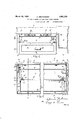
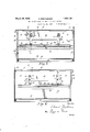
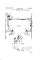
Inthe accompanying illustrations: Figure 1 is a fragmentary front elevation 49 of one end of a gas stove constructed in accordance with my invention. Figure 2 1s a fragmentary, enlarged, vertical, transverse section taken on line 2-2, Fig. 3, and with the I burners removed. Figures? and 4 are frag- 'mentary, enlarged, vertical,1longitudinal sections through the burner compartment taken on correspondingly numbered lines of Fig. 2-. Figure 5 is a still more enlarged, fragmentary, vertical, transverse sectionthrough the burner compartment and taken on lines 55,,
which is disposed below- 1930. Serial No. 461,242..
Figs. 3 and 4. Figure 6 is a considerably enlarged fragmentary perspective of themeondaryhanger.
In the following description; similar char-.
acters of reference indicate like parts in the several figures of the drawings. 7
My invention may be embodied invarious forms and instove constructions of different constructions and the present application is therefore to be regarded merely as one organizationr which satisfactorily carries out the invention in practice. As here shown, the same is. constructed as follows:
Referring to -1, 10 represents the base :oer a suitable distance above the ln'tchen floor; 11 is the usual oven; 12 is the flat, horizontal top of the stove upon which such culinary operations as frying, boiling, etcg, are carried on and 13 is the back of the stove. Said top .12'of the stove is heated by a plurality of gas burners 14 each of which is lo:
cated directly below a lid opening '15 in the usual manner. I I
Each pair'of these gas burners 14 is suitably mounted upon a burner rod or bar 16,
which extends horizontally and transversely of the burner compartment 17 just below the V stove top 12. Th'einner endofeachb-urner bar 1-6 is located within and is entirelyenclosed by a retaining socket 18 which isformed-inte 'rally with and projects horizontally and outwardly from'a primary hanger 20. The latter is secured to the oven wall 21 by a bolt 22, but it should be noticed that this bolt has two nuts 28 and 24, the purpose of which is to permit of removing the hanger 20 without disturbing the nut 23' or its bolt 22. The value of this construction will hereinafter be described as to its efiect upon the construc- 26. The purposeof this double wall construction is to shield said outer 'wall 25 from i the excessively hot radiant rays emanating from the burners 14, and to thereby prevent said main outer wall from becoming so. hot 7 as to burn the clothing or to cause a flaking off of the enamel with which it is usually coated on the outside. It is only necessary, however, to extend the insulating wall 26 a relatively short distance down from the stove top 12 to satisfactorily accomplish this pur pose.
Secured by a bolt 27 and nut 28 to said vertical, insulating wall 26 is a secondary hanger 30. Formed preferably integrally with and projecting horizontally and inwardly from the main body of said hanger 30 is a semi-socket 31 (see Figs. 3, 5 and 6) into which the outer end of its companion burner bar 16 is adapted to be dropped after the inner end of saidbar has first been inserted into the retaining socket 18.
Said outer end of said burner bar 16 is caused to be positively retained within said semi-socket 31 by means of a bracket-shaped clamp or cleat 32 whose vertical flange 33 has a single cored hole 3% which is adapted to he slipped over the outer end of the bolt 27. When said cleat 32 is thus in place, it is secured in place by a nut 35, the latter being threaded onto the outer end of said bolt 27. The provision of only a single hole 34 in the cleat 32 is obviously an inexpensive construction both as to manufacturing and assembly costs. It, however, does not ensure a correct lateral position ng of said cleat 32. This object is accomplished by the provision of a pair of centering flanges 36-36 which, when said cleat is in proper position, embrace opposite sides of the peripheral face of the semi-socket 31 and thereby center the cleat properly and prevent any displacement thereof after the nut 35 has been screwed tight. This cleat 32 together with the semipocket 31 constitutes what may be termed a split pocket to distinguish the same from the annular retaining pocket 18. These centering flanges 36 of the cleat 32 extend over and some distance beyond the side walls of their companion semi-socket 31 and thereby constitute a cover for the same whereby particles of scale and dirt are prevented from dropping into the space between the periphery of the burner bar 16 and the inner faces of the semi-socket 31.
Formed integrally with said cleat 32 and projecting downwardly and centrally therefrom is a pressure rib 39 which is adapted to bear against the upper face of its companion burner bar and to thereby retain the same positively and securely in the semi-socket 31. Obviously, the central main portion of the cleat could operate in the capacity of this centering rib 39, but by making the same relatively narrow and extending the same downwardly a slight distance below the main body of said cleat, as illustrated, a construction is obtained which permits of easily grinding or filing away the lower face of said rib, thereby causing it to fit properly if it should happen to project downward too far to permit of easily slipping the cleat over the inner end of the bolt 27. This cleat 32 and also both hangers 20 and 30 are preferably sand cast and are manufactured without any machining (other than the hand grinding off of the rough casting fins) and therefore certain variations in size, incidental to any sand cast article, are to be expected. This is why, occasionally, a grinding or filing operation upon the pressure rib 39, when assembling the stove, is to be normally expected and suitably provided for as is the case in the present construction.
It is usually desirable that the stove be equipped with a plurality of pairs of burners 14 and hence also with a plurality of burner bars 16. This necessitates the provision of a pair of primary hangers 20 and a pair of secondary hangers 30. In the present invention the two secondary hangers 30 are integrally joined by a uniting bar 37 as in Fig. 3, while the primary hangers 20 are integrally joined by a similar uniting bar 38. This integral construction provides automatically for a proper spacing between each companion pair of hangers and also enables each of said pairs to be rigidly connected to the adjacent wall of the burner compartment by the use of only two bolts. At the same time the cast construction of each pair of hangers permits of a solid and broad faced socket for each end of each burner bar 16, such a result not being otherwise inexpensively accomplished. In addition, such a cast construction has the advantage that the temperature at which ordinary cast iron is deformable is considerably higher than that at which sheet iron or steel is deformable, this being a matter quite different from the factor of ultimate strength of these materials. This matter particularly affects the present invention in that the parts which support the opposite ends of the burner bars are subjected to very high temperatures.
The integral construction of the two primary hangers 20 also has the advantage of greatly facilitating the assembly of the same in the stove. As before stated, the two hanger bolts 22 are permanently secured to the oven wall 21 by nuts 23, the outer threaded ends of said bolts projecting some distance beyond the outer faces of said nuts 23. This permits the pair of primary hangers 20, together with their integral uniting bar 38, to be slipped as a single unit over said outwardly projecting ends of said bolts 22 and selfsupported upon the same while the nuts 24 are being tightened. The latter operation is facilitated by the fact that said bolts 22 do not have to be restrained against turning while said outer nuts 24 are being turned inasmuch as the bolts themselves are rigidly held in place on the oven wall .2lby the nuts 23. I f
The lower end of each of the secondary hangers 30 is provided with an integral spacer leg40 which projects horizontally outward from the main body of said hanger and bears with its outer face against the inner face of the outer wall 25 of the burner compartment. Inasmuch as the upper ends of said secondary hangers 30 are secured to the inner or insulating wall 26 of the burner coinpartment, it follows that by this construction, these two walls 25 and 26 are heldapart in properly spaced relation. This prevents the insulation wall 26 from warping and sagging which would otherwise result as a consequence of the high temperatures to which it is subjected at its upper end. At the same time the cool currents of air flowing upward along the inner faces of said outer wall 25 are free to flow directly up into the space between the outer and inner walls 25 and 26 and thence to the burners 14, this flow of cool air not being materially obstructed by the relatively narrow width of these secondary hangers 30 and their spacer legs 40, as is apparent from Fig. 3. y This same consideration applies to the primary hangers 20.; vertical air currents adjacent theoven wall 21 not being materially obstructed by said primary hangers 20.
Formed integrally on the primary and secondary hangers 20 and 30 are brackets 41 and 411 respectively each of which extends horizontally away from the adjacent burner compartment wall and has secured to its outer, under face by bolts .42 or otherwise, a slide plate 43 extending horizontally and longitudinally of the burnercompartment 17. These slide plates are preferably of identical form and each is constructed of sheet metal and extends vertically downward from its companion bracket 41 or 411 to form lateral guide walls 44, the lower extremity of which is bent sharply horizontally to form a supporting shelf 45. Slidably' supported upon the pair of shelves 45 of the two slide plates 43 is a refuse collector or'drip pan 46 (see Figs. 2 and 3) which is laterally guided between the aforesaid guide walls 44 of said slide plates. This drip pan is useful in catching any dirt which drops from the burners 14 of any cooking substance which may boil or be spilled out of the culinary utensils being heated on'the stove top 12. It will be noticed that the slide plate 43 extends over the upper, outer edge of the drip pan 46. This ensures that when said drip pan is pulled more than half way out, its front end cannot drop down until the entire drip pan is completely disengaged from said slide plate.
The inner edge of each supporting shelf 45 is bent horizontally outward and back upon the lower face of itself and is thenbent sharply downward to form a vertical guiding or retainingflange 47 Between the opposing faces of the two guiding flanges of the two slide plates 43 and guided laterally thereby is the usual, so-called warming or service drawer 48 in which various culinary receptacles may be placed to be kept moderately warm after the food therein has been sufficiently prepared. This service drawer is provided with a suitable handle 50 (to facilitate its-being slid, in or out) and rests upon a burner compartment floor 51 as shown in Figs. 2 and 3.. For the sake of appearance its front face is carried up far enough to conceal the front edge of the drip pan 46. Y The slide plate 43 extends'over the upper, outer edge of this servicedrawer and thereby prevents its front end from dropping down when the same is pulled more than half way out.
It will be noticed that the vertical retaining flange 47 of each slide plate 43 is spaced a considerable distance laterally inward or away from its adjacent burner compartment wall. This ensuresthat each of the longitu I dinal, vertical sides of the service drawer 48 will be spaced a considerable distance inward or away from the adj acent walls of the burner compartment 17 as best shown in Fig. 2. This arrangement enables air to pass up through the space between the burner compartment floor 51 and the burner compartment side walls 25 and 21, continuing thence up between the sides of the drawer 48 and the burner compartment side walls, through the space between the slide plates 43 and the burner compartment side walls and then to the gas burners 14 where it is burned in combination,
with the fuel gas issuing therefrom. The combined length of the spacer leg 40 plus the length of the bracket 411 of the secondary hanger 30 is greater than the length ofthe bracket 41 of the primary hanger 20. By
In the construction shown in the drawings, air is prevented from entering the front of the burner compartment 17 by reason of the obstruction caused by the front of the service drawer and also by the obstruction of an apron 52 whichis secured to the vertical front face of the stove by screws 53 or otherwise.
This apron serves to give the front of the stove a neater and more finished appearance.
In case this apron 52 is omitted (as in the 5 less expensive models of stoves) then one or both of the retaining flanges 47 of the guide strip 43 may be suitably shifted in position or omitted entirely, and the service drawer 48 correspondingly increased in width inasmuch as in such case an adequate supply of air is provided to the burners without any air channels laterally adjacent the service drawer.
I claim as my invention:
1. A gas stove comprising a burner compartment; a hanger secured to one wall thereof and provided with a semi-socket; a burner bar having its one end received within said semi-socket; a cleat arranged adjacent said Semi-socket and adapted to bear against the adjacent face of said burner bar and having a centering flange; and a gas burner mounted on said burner bar.
2. A gas stove comprising a burner compartment; a hanger secured to one well thereof and provided with a semi-socket; burner barhaving its one end received within said semi-socket; a cleat arre" d adjacent said semi-socket and having a pressur rib adapted to bear against the adjacent face of said burner bar so as to retain the same within said semi-socket; and a :urner mounted on said burner bar.
3. A gas stove compris ng a burner compartment having an inner and an outer wall: a hanger secured to saio inner compartment wall and having a socket and also hav ng a spacer leg bearing against the adjacent face of said outer compartment wall: a burner bar having one of its ends received within said socket: and a gas burner mounted on said burner bar.
4. A gas stove comprising a burner compartment: a burner bar; a hanger secured to one wall thereof having a socket adapted to receive one end of said burner bar: a relativelv long slide plate secured to said hanger; a drip pan slidahly arranged in said slide plate: and a burner mounted on said burner bar.
5. A gas stove comprising a burner compartment: a hiirner bar; a hanger secured to one wall thereof having a socket adapted to receive one end of said burner bar: a relatively long slide plate secured to said hanger and provided with a guide flange; a dr? 1: hearing against said guide flange; and a burner mounted on said burner bar.
6. A gas stove COHlIHlSlIlg a burner compartment: a burner bar; a hanger secured to one Wall thereof having a socket adapted to receive one end of said burner bar; a relatively long slide plate secured to said hanger and having a guide flange in spaced relation 55 :0 the adjacent wall of said compartment; a
drawer bearing against said guide flange; and a burner mounted on said burner bar.
7. A gas stove comprising a burner compartment; a burner bar; a hanger secured to one wall thereof having a socket adapted to receive one end of said burner bar; a relatively long slide plate secured to said hanger and having a guide flange; a drawer bearing against said guide flange; a drip pan slidahly arranged in said slide plate; and a burner mounted on said burner bar.
8. A gas stove comprising a burner compartment; a plurality of hangers arranged at the front and rear ends of said coinpart- L ment, each having a socket; a plurality of burner bars having their ends receivable within said sockets; a single slide plate secured adjacent its opposite ends to said hangers; a drip pan slidably mounted on said slide plate; and gas burners mounted on said burner bars.
9. A gas stove comprising a burner compartment; a plurality of hangers arranged at the front and rear ends of sai d compartment, each having a socket; a plurality of burner bars having their ends receivable within said sockets; a single slide plate secured adjacent its opposite ends to said hangers and having a guide flange; a drawer hearing against said guide flange; and gas burners mounted on said burner bars.
10. A gas stove comprising a burner compartment; a uniting bar; a pair of hangers having sockets and secured to opposite ends of said uniting bar; burner bars arranged in said sockets; and gas burners mounted on said burner bars.
In testimony whereof I hereby afiix my signature.
EDWARD BREITWIESER.
ill
ISO
Priority Applications (1)
| Application Number | Priority Date | Filing Date | Title |
|---|---|---|---|
| US461242A US1851150A (en) | 1930-06-14 | 1930-06-14 | Gas stove burner-bar and slide-plate support |
Applications Claiming Priority (1)
| Application Number | Priority Date | Filing Date | Title |
|---|---|---|---|
| US461242A US1851150A (en) | 1930-06-14 | 1930-06-14 | Gas stove burner-bar and slide-plate support |
Publications (1)
| Publication Number | Publication Date |
|---|---|
| US1851150A true US1851150A (en) | 1932-03-29 |
Family
ID=23831755
Family Applications (1)
| Application Number | Title | Priority Date | Filing Date |
|---|---|---|---|
| US461242A Expired - Lifetime US1851150A (en) | 1930-06-14 | 1930-06-14 | Gas stove burner-bar and slide-plate support |
Country Status (1)
| Country | Link |
|---|---|
| US (1) | US1851150A (en) |
Cited By (2)
| Publication number | Priority date | Publication date | Assignee | Title |
|---|---|---|---|---|
| US2559979A (en) * | 1945-02-23 | 1951-07-10 | Arthur E Martois | Multiple gas burner |
| US2691369A (en) * | 1947-04-17 | 1954-10-12 | Gibson Refrigerator Co | Drip pan for cooking ranges |
-
1930
- 1930-06-14 US US461242A patent/US1851150A/en not_active Expired - Lifetime
Cited By (2)
| Publication number | Priority date | Publication date | Assignee | Title |
|---|---|---|---|---|
| US2559979A (en) * | 1945-02-23 | 1951-07-10 | Arthur E Martois | Multiple gas burner |
| US2691369A (en) * | 1947-04-17 | 1954-10-12 | Gibson Refrigerator Co | Drip pan for cooking ranges |
Similar Documents
| Publication | Publication Date | Title |
|---|---|---|
| US1650634A (en) | Broiler pan | |
| US3122134A (en) | Gas heated oven construction | |
| US3008406A (en) | Cooking unit | |
| US1889218A (en) | Combination rack and pan | |
| US2161537A (en) | Gas range construction | |
| US1800052A (en) | Oven lining and rack supported thereby | |
| US1851150A (en) | Gas stove burner-bar and slide-plate support | |
| US2411993A (en) | Combination broiler and server for domestic ranges | |
| US1169168A (en) | Drip-pan. | |
| US2101180A (en) | Portable cooker | |
| US2222065A (en) | Combination combustion and electric stove | |
| US2879763A (en) | Domestic appliance | |
| US2498554A (en) | Detachable bottom for ovens or broilers | |
| US2384262A (en) | Heating apparatus | |
| US2897813A (en) | Food service equipment unit | |
| US1991503A (en) | Closed top stove | |
| US2329760A (en) | Cooking appliance | |
| US2111056A (en) | Electric cooking utensil | |
| US2136100A (en) | Heat conserver for ranges | |
| US1156087A (en) | Flame-shield for gas-stoves. | |
| US2054589A (en) | Stove | |
| US3176677A (en) | Gas range | |
| US1404134A (en) | Water-heating apparatus | |
| US2331950A (en) | Gas heater | |
| US2025896A (en) | Gas stove |