US1851141A - Tire lock - Google Patents
Tire lock Download PDFInfo
- Publication number
- US1851141A US1851141A US464766A US46476630A US1851141A US 1851141 A US1851141 A US 1851141A US 464766 A US464766 A US 464766A US 46476630 A US46476630 A US 46476630A US 1851141 A US1851141 A US 1851141A
- Authority
- US
- United States
- Prior art keywords
- cap
- casing
- tire
- latch
- abutment
- Prior art date
- Legal status (The legal status is an assumption and is not a legal conclusion. Google has not performed a legal analysis and makes no representation as to the accuracy of the status listed.)
- Expired - Lifetime
Links
Images
Classifications
-
- F—MECHANICAL ENGINEERING; LIGHTING; HEATING; WEAPONS; BLASTING
- F16—ENGINEERING ELEMENTS AND UNITS; GENERAL MEASURES FOR PRODUCING AND MAINTAINING EFFECTIVE FUNCTIONING OF MACHINES OR INSTALLATIONS; THERMAL INSULATION IN GENERAL
- F16B—DEVICES FOR FASTENING OR SECURING CONSTRUCTIONAL ELEMENTS OR MACHINE PARTS TOGETHER, e.g. NAILS, BOLTS, CIRCLIPS, CLAMPS, CLIPS OR WEDGES; JOINTS OR JOINTING
- F16B41/00—Measures against loss of bolts, nuts, or pins; Measures against unauthorised operation of bolts, nuts or pins
- F16B41/005—Measures against unauthorised operation of bolts, nuts or pins
-
- Y—GENERAL TAGGING OF NEW TECHNOLOGICAL DEVELOPMENTS; GENERAL TAGGING OF CROSS-SECTIONAL TECHNOLOGIES SPANNING OVER SEVERAL SECTIONS OF THE IPC; TECHNICAL SUBJECTS COVERED BY FORMER USPC CROSS-REFERENCE ART COLLECTIONS [XRACs] AND DIGESTS
- Y10—TECHNICAL SUBJECTS COVERED BY FORMER USPC
- Y10T—TECHNICAL SUBJECTS COVERED BY FORMER US CLASSIFICATION
- Y10T70/00—Locks
- Y10T70/50—Special application
- Y10T70/5093—For closures
- Y10T70/554—Cover, lid, cap, encasing shield
- Y10T70/5562—Removable
- Y10T70/5575—Directly seating
- Y10T70/558—Cover-carried lock
- Y10T70/5584—Dead bolt
-
- Y—GENERAL TAGGING OF NEW TECHNOLOGICAL DEVELOPMENTS; GENERAL TAGGING OF CROSS-SECTIONAL TECHNOLOGIES SPANNING OVER SEVERAL SECTIONS OF THE IPC; TECHNICAL SUBJECTS COVERED BY FORMER USPC CROSS-REFERENCE ART COLLECTIONS [XRACs] AND DIGESTS
- Y10—TECHNICAL SUBJECTS COVERED BY FORMER USPC
- Y10T—TECHNICAL SUBJECTS COVERED BY FORMER US CLASSIFICATION
- Y10T70/00—Locks
- Y10T70/50—Special application
- Y10T70/5611—For control and machine elements
- Y10T70/5854—Bolt, nut, stud, stud-cap
- Y10T70/5867—Encased
-
- Y—GENERAL TAGGING OF NEW TECHNOLOGICAL DEVELOPMENTS; GENERAL TAGGING OF CROSS-SECTIONAL TECHNOLOGIES SPANNING OVER SEVERAL SECTIONS OF THE IPC; TECHNICAL SUBJECTS COVERED BY FORMER USPC CROSS-REFERENCE ART COLLECTIONS [XRACs] AND DIGESTS
- Y10—TECHNICAL SUBJECTS COVERED BY FORMER USPC
- Y10T—TECHNICAL SUBJECTS COVERED BY FORMER US CLASSIFICATION
- Y10T70/00—Locks
- Y10T70/50—Special application
- Y10T70/5889—For automotive vehicles
- Y10T70/5982—Accessories
- Y10T70/5987—Spare or mounted wheel or tire
- Y10T70/5991—Tire or rim only
Definitions
- the present invention relates in general to supported upon tire carriers at the rear of the vehicles.
- An object of the invention is to provide an improved tire lock which is simple, compact 1 and rigid in construction, and which is also highly efiicient in operation.
- a more specific object of the present invention is to provide various improvements in the details of construction and in the mode of operating spare tire locking devices of the general type disclosed in the said patent, whereby the defects of such prior structures, are substantially eliminated.
- the present improved locking structure provides maxi- 'mum protection for the key operable cylinder,
- the present invention also contemplates improvements in the formation of the closure cap whereb the same may be conveniently applied, an subsequently removed with the aid of its key, but not otherwise.
- the improvement further contemplates provision of an extremely comthe rear closure cap by another.
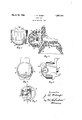
- Fig. 1 is a central vertical section through one 'of the improved spare tire locks,'showing the same applied to clamp a spare tire upon its support.
- Fig. 2 a side elevation of the improved spare tire locking device.
- Fig. 3 is a rear view of theimproved spare tire locking device.
- Fig. 4 is a top viewof the improved spare tire locking device.
- Fig. 5 is an internal view of the closure cap of the improved tire lockin device.
- the improved spare tire loc g device specifically shown in the drawings by way of illustration, comprises in neral a main casing 2 having a restricte front opening 20 adapted for the reception of the rearwardly cal formation, and the front upper portion of this casing is provided with several contact lugs 11 adapted to coact with the rear upper portion of the bottom art of an annular tire carrier 10 associate with the rear of a vehicle.
- the lower front portion of the casing 2 is formed for clamping coaction with the rear inner portion of the tire supporting rim 9 mounted upon the carrier 10, and has a tapered holding cleat 12 formed for disposition between the carrier 10 and the rim 9.
- the spare tire 21 carried by the rim 9, is of usual construction, being provided with an inner tube havin a valve stem which penetrates the rim 9.
- he rear casing opening 20 is preferably vertically elongated so as to rmit the casing 2 to assume proper clampmg position relative to the tire carrier 10 and the rim 9 without obstruction by the clamping bolt 7 and the bolt 7 may be rigidly attached to the carrier 10 in any suitable manner.
- the rear ortion of the main casing 2 is rovided with an annular end socket 19 ormed to receive the peripheral edge of the closure cap 3 so as to prevent the cap from being pried from the casing by insertion of a shar implement thereunder.
- the interior o the casing 2 is rovided with an abutment 15 which is pre erably of annular formation in order to permit accurate I118.- chining thereof with a tool revolving about the central casing axis.
- the casing 2 may be formed of cast metal and the exterior thereof may be neatly finished by enameling or otherwise.
- the closure cap 3 may be formed as a die casting with its exterior plated and polished, and comprises a shell of substantially spherical form, bulging rearwardly away from the casin 2.
- the cap 3 constitutes a support for t e locking mechanism which comprises a key operable cylinder 4 having a key hole 17 exposed to the exterior of the cap 3, and also having a crank pin 5; a latch 6 pivotally supported upon the cap 3 and movable by the crank pin 5; and a coil spring 16 secured to the casing 3 and cooperating with the latch 6 to constantl urge the locking hook of the latch away rom the cap axis.
- the ke hole 17 of the lock cylinder is accessible on y from the side of the casing 2 and cap 3, and may be concealed by means of a pivoted shield 18 as shown in Figs. 2 and 3.
- the lock cylinder 4 is dis osed withina bore extending transversely o the cap axis, and may be locked within this bore in any suitable manner.
- the latch hook is adapted to engage the casing abutment 15 as shown in Fig. 1, and the portion of the cap 3 remote from the latch 6 is provided with a positioning projection 13 and with retaining projections 14 which are also cooperable with the abutment 15.
- the clamping nut 8 is completely concealed, and the cap 3 can only be removed with the The cap 3 cannot be pried loose, and the outwardly convex formation of this cap serves to deflect any object impinging a ainst the rear thereof. he position 0 the lock cylinder transversely of the cap axis, prevents damaging of thec-ylinder 4 and the key hole 17 by impact from an approaching vehicle, and also protects the key hole from dirt and water splashing against the locking device.
- the latch 6 is held in firm engagement with the abutment 15 by the spring 16, and the projections 14 likewise firmly en age the abutment 15 at the opposite side 0 the casing 2.
- the formation of-the end of the latch 6 and of the casing 2, is such as to permit the latch to readily slip past the adjacent abutment 15, the spring 16 being compressed during passage of the latch over the abutment and serving to automatically snap the latch into locking position when the parts are properly assembled.
- the improvement provides a tire lock which is simple, compact and rigid in construction, and which is moreover highly efiicient in operation.
- the cap 3 ma be conveniently applied to or removed rom the casing 2, and all parts are efiectively protected against damage.
- the device may be applied to most standard automobiles wherein the spare tire is mounted at the rear of the vehicle, and has proven extremely satisfactory in commercial operation.
- testimon whereof the signature of the inventor is a ed hereto.
Landscapes
- Engineering & Computer Science (AREA)
- General Engineering & Computer Science (AREA)
- Mechanical Engineering (AREA)
- Body Structure For Vehicles (AREA)
Description
J. R. THORP TIRE LOCK March 29, 1932..
Filed June so, 1930 0 ull.l
Patented 29, .1932
- UNITED STATES; {PATENT OFFICE "JOEL rnonr, or wnsr ALMS, wrscoxsm, assrcmon are THE rnn'ron comm,
orwnsrnnus, Wisconsin, A 'coaronarron or unsemsrsm TIRE LOOK Application meagune 30,1930. Serial no. 4643518.
The present invention relates in general to supported upon tire carriers at the rear of the vehicles.
An object of the invention is to provide an improved tire lock which is simple, compact 1 and rigid in construction, and which is also highly efiicient in operation.
It has heretofore been proposed, as specifically illustrated in United States Patent No. 1,339,075, granted May 4, 1920, to provide a tire lock for a spare tire mounted at the rear of a vehicle, consisting of a casing for housing a clamping nut and having an opening for permitting access to the nut, and a removable cap for normally sealing the casing opening. In this prior locking structure, the cap isretained in place upon the casing, by means of a mechanism including a key operable cylinder and crank pin, the operating portion of which is exposed to the rear of the cap which is associated with the extreme rear portion of the casing and of the vehicle. The disposition of the elements is such, that the key operable portion of the cylinder is constantly exposed to the danger of being damaged by impact from an approaching vehicle, to such an extent that the lock cannot be manipulated even with the aid of its key.
The construction of the casing, closure cap, and locking mechanism of the prior locking devices of this kind, is moreover such, that the locln'ng mechanism is not sufiiciently protected and cannot be conveniently manipulated to permit removal and attachment of the closure cap, and that the entire structure is insufliciently rigid and secure to serve its contemplated purpose.
A more specific object of the present invention is to provide various improvements in the details of construction and in the mode of operating spare tire locking devices of the general type disclosed in the said patent, whereby the defects of such prior structures, are substantially eliminated. The present improved locking structure provides maxi- 'mum protection for the key operable cylinder,
preventing fpossible damaging thereof due to bumping 0 car, and also protecting the key hole against entry of dirt and water. The present invention also contemplates improvements in the formation of the closure cap whereb the same may be conveniently applied, an subsequently removed with the aid of its key, but not otherwise. The improvement further contemplates provision of an extremely comthe rear closure cap by another.
pact andrigid spare tire lock which maiyl'lbe .manufactured at minimum cost, and w presents a neat appearance. These and other ob ects and advantages of the invention will {appear from the following detailed descrip- A clean conception of an embodiment of the invention and of the mode of constructing and of vmanipulating tire locks built in accordance therewith, may be had by referring to the drawings accompanying and forming a part of this specification in which like reference characters designate the same or similar parts in the several views.
Fig. 1 is a central vertical section through one 'of the improved spare tire locks,'showing the same applied to clamp a spare tire upon its support.
Fig. 2 a side elevation of the improved spare tire locking device.
Fig. 3 is a rear view of theimproved spare tire locking device.
Fig. 4 is a top viewof the improved spare tire locking device.
Fig. 5 is an internal view of the closure cap of the improved tire lockin device.
The improved spare tire loc g device specifically shown in the drawings by way of illustration, comprises in neral a main casing 2 having a restricte front opening 20 adapted for the reception of the rearwardly cal formation, and the front upper portion of this casing is provided with several contact lugs 11 adapted to coact with the rear upper portion of the bottom art of an annular tire carrier 10 associate with the rear of a vehicle. The lower front portion of the casing 2 is formed for clamping coaction with the rear inner portion of the tire supporting rim 9 mounted upon the carrier 10, and has a tapered holding cleat 12 formed for disposition between the carrier 10 and the rim 9. The spare tire 21 carried by the rim 9, is of usual construction, being provided with an inner tube havin a valve stem which penetrates the rim 9. he rear casing opening 20 is preferably vertically elongated so as to rmit the casing 2 to assume proper clampmg position relative to the tire carrier 10 and the rim 9 without obstruction by the clamping bolt 7 and the bolt 7 may be rigidly attached to the carrier 10 in any suitable manner.
The rear ortion of the main casing 2 is rovided with an annular end socket 19 ormed to receive the peripheral edge of the closure cap 3 so as to prevent the cap from being pried from the casing by insertion of a shar implement thereunder. The interior o the casing 2 is rovided with an abutment 15 which is pre erably of annular formation in order to permit accurate I118.- chining thereof with a tool revolving about the central casing axis. The casing 2 may be formed of cast metal and the exterior thereof may be neatly finished by enameling or otherwise.
The closure cap 3 may be formed as a die casting with its exterior plated and polished, and comprises a shell of substantially spherical form, bulging rearwardly away from the casin 2. The cap 3 constitutes a support for t e locking mechanism which comprises a key operable cylinder 4 having a key hole 17 exposed to the exterior of the cap 3, and also having a crank pin 5; a latch 6 pivotally supported upon the cap 3 and movable by the crank pin 5; and a coil spring 16 secured to the casing 3 and cooperating with the latch 6 to constantl urge the locking hook of the latch away rom the cap axis. The ke hole 17 of the lock cylinder is accessible on y from the side of the casing 2 and cap 3, and may be concealed by means of a pivoted shield 18 as shown in Figs. 2 and 3. The lock cylinder 4 is dis osed withina bore extending transversely o the cap axis, and may be locked within this bore in any suitable manner. The latch hook is adapted to engage the casing abutment 15 as shown in Fig. 1, and the portion of the cap 3 remote from the latch 6 is provided with a positioning projection 13 and with retaining projections 14 which are also cooperable with the abutment 15.
When the cap 3 is locked to the casing 2,
.aid of the key.
the clamping nut 8 is completely concealed, and the cap 3 can only be removed with the The cap 3 cannot be pried loose, and the outwardly convex formation of this cap serves to deflect any object impinging a ainst the rear thereof. he position 0 the lock cylinder transversely of the cap axis, prevents damaging of thec-ylinder 4 and the key hole 17 by impact from an approaching vehicle, and also protects the key hole from dirt and water splashing against the locking device. The latch 6 is held in firm engagement with the abutment 15 by the spring 16, and the projections 14 likewise firmly en age the abutment 15 at the opposite side 0 the casing 2.
When the releasing key is applied and the cylinder 4 turned within its confining bore, t e crank pin 5 becomes effective to retract the latch 6 from the abutment 15, against the action of the coil spring 16, thus permitting free removal of the projections14 from the abutment 15 and subsequent withdrawal of the cap 3. The clampin nut 8 may then be readil manipulated an the casing 2 removed i desired whereupon the spare rim 9 and tire 21 are freely removable from the carrier 10. The closure cap 3 may however be applied to the casing 2, without the aid of the key, by merely inserting the projection 13 in the groove provided in the casing 2 in order to properly position the cap 3,
and by subsequently snapping the cap 3 in place. The formation of-the end of the latch 6 and of the casing 2, is such as to permit the latch to readily slip past the adjacent abutment 15, the spring 16 being compressed during passage of the latch over the abutment and serving to automatically snap the latch into locking position when the parts are properly assembled.
From the foregoing description, it will be apparent that the improvement provides a tire lock which is simple, compact and rigid in construction, and which is moreover highly efiicient in operation. The cap 3 ma be conveniently applied to or removed rom the casing 2, and all parts are efiectively protected against damage. The device may be applied to most standard automobiles wherein the spare tire is mounted at the rear of the vehicle, and has proven extremely satisfactory in commercial operation.
It should be understood that it is not intended to limit the invention to the exact details of construction and to the precise mode of operating locking devices, herein shown and described, for various modifications within the scope of the claims may occur to persons skilled in the art.
It is claimed and desired to secure by Letters Patent:
1. The combination with a horizontally disposed retaining bolt for spare tires having a retaining nut thereon, of a casing having an annular wall adapted to surround said nut and the end of said bolt and also having an integral end portion formed to engage said nut and the tire rim when the latter is locked I in place, the opposite end of said wall having a side recess and being'provided with a ta- 1 pered seating extending around said end and terminating at said recess, a cap engageableo with said tapered seating and having a horisaid latch located in said bore and manipulzontal bore disposable within said recess, a latch pivotally supported by said cap and cooperable with an abutment on the interior of said wall, and a cylinder lock for actuating able from the recessed side of said casing.
2. The combination with a horizontally disposed retaining bolt for spare tires having a retaining nut thereon, of a casing having an annular wall adapted to surround said nut and the end of said bolt and also having an integral end portion formed to engage said nutand the tire rim when the latter is locked inplace, the opposite end of said wall having a side recess and being provided with atapered seating extending around said end and terminating at said recess, a cap engageable with said tapered seating and having a horizontal bore disposable within said re- .cess, a latch pivotally supported by said cap and cooperable with an abutment on the interiorof said wall, a spring carried by said cap for constantly urging said latch toward latching position, and a cylinder lock for actuating said latch located in said bore and manipulable irom the recessed side of said casing.
In testimon whereof the signature of the inventor is a ed hereto.
: JOEL R. THORP.
Priority Applications (1)
| Application Number | Priority Date | Filing Date | Title |
|---|---|---|---|
| US464766A US1851141A (en) | 1930-06-30 | 1930-06-30 | Tire lock |
Applications Claiming Priority (1)
| Application Number | Priority Date | Filing Date | Title |
|---|---|---|---|
| US464766A US1851141A (en) | 1930-06-30 | 1930-06-30 | Tire lock |
Publications (1)
| Publication Number | Publication Date |
|---|---|
| US1851141A true US1851141A (en) | 1932-03-29 |
Family
ID=23845143
Family Applications (1)
| Application Number | Title | Priority Date | Filing Date |
|---|---|---|---|
| US464766A Expired - Lifetime US1851141A (en) | 1930-06-30 | 1930-06-30 | Tire lock |
Country Status (1)
| Country | Link |
|---|---|
| US (1) | US1851141A (en) |
Cited By (3)
| Publication number | Priority date | Publication date | Assignee | Title |
|---|---|---|---|---|
| US3823856A (en) * | 1971-09-30 | 1974-07-16 | Honda Motor Co Ltd | Accessorial device for holding a helmet or the like on an autobicycle |
| US20100186465A1 (en) * | 2007-07-23 | 2010-07-29 | Frantz Donald R | Universal electronics lock |
| US10000945B2 (en) * | 2007-07-23 | 2018-06-19 | Donald R. Frantz | Universal electronics lock |
-
1930
- 1930-06-30 US US464766A patent/US1851141A/en not_active Expired - Lifetime
Cited By (4)
| Publication number | Priority date | Publication date | Assignee | Title |
|---|---|---|---|---|
| US3823856A (en) * | 1971-09-30 | 1974-07-16 | Honda Motor Co Ltd | Accessorial device for holding a helmet or the like on an autobicycle |
| US20100186465A1 (en) * | 2007-07-23 | 2010-07-29 | Frantz Donald R | Universal electronics lock |
| US20180058495A1 (en) * | 2007-07-23 | 2018-03-01 | Donald R. Frantz | Universal electronics lock |
| US10000945B2 (en) * | 2007-07-23 | 2018-06-19 | Donald R. Frantz | Universal electronics lock |
Similar Documents
| Publication | Publication Date | Title |
|---|---|---|
| US3858419A (en) | Two-part protective cover for padlocks | |
| US4401247A (en) | Fastening device for supporting brackets or luggage racks for automotive vehicles | |
| US3526110A (en) | Trailer coupler cover lock | |
| US2882636A (en) | Safety cap for trigger guards of firearms | |
| US1944535A (en) | Cap locking device | |
| CA2075125C (en) | Security device for securing a spare tire | |
| US5303971A (en) | Tailgate release handle security device | |
| US1851141A (en) | Tire lock | |
| US4366683A (en) | Locking latch for a hatch door or the like | |
| US1339075A (en) | Lock-housing for screws and bolts | |
| US4468064A (en) | Anti-theft mechanism for removable automobile roof panel | |
| US1934319A (en) | Emergency key holder | |
| US1747201A (en) | Locking means for receptacle closures | |
| US2126391A (en) | Lock | |
| US1812467A (en) | Tire carrier lock | |
| US3313136A (en) | Lock cylinder cover | |
| US2723585A (en) | Anti-theft device for automobile hub caps | |
| US1570477A (en) | Locking mechanism for the spare tires of automobiles | |
| US2134761A (en) | Spare wheel cover and lock | |
| US2077698A (en) | Locking mechanism | |
| US2212033A (en) | Mounting for rear view mirrors | |
| JPS6315079Y2 (en) | ||
| US1335160A (en) | Theft-preventing device for motor-cars | |
| US2085725A (en) | Spare wheel lock | |
| US1412646A (en) | Automobile tire lock |