US185111A - Improvement in clamps for holding hand-rail wreath-pieces - Google Patents
Improvement in clamps for holding hand-rail wreath-pieces Download PDFInfo
- Publication number
- US185111A US185111A US185111DA US185111A US 185111 A US185111 A US 185111A US 185111D A US185111D A US 185111DA US 185111 A US185111 A US 185111A
- Authority
- US
- United States
- Prior art keywords
- wreath
- rail
- pieces
- clamps
- piece
- Prior art date
- Legal status (The legal status is an assumption and is not a legal conclusion. Google has not performed a legal analysis and makes no representation as to the accuracy of the status listed.)
- Expired - Lifetime
Links
- 235000019687 Lamb Nutrition 0.000 description 4
- 230000000881 depressing Effects 0.000 description 4
- 230000000994 depressed Effects 0.000 description 2
- 229920000638 styrene acrylonitrile Polymers 0.000 description 2
Images

Classifications
-
- B—PERFORMING OPERATIONS; TRANSPORTING
- B23—MACHINE TOOLS; METAL-WORKING NOT OTHERWISE PROVIDED FOR
- B23D—PLANING; SLOTTING; SHEARING; BROACHING; SAWING; FILING; SCRAPING; LIKE OPERATIONS FOR WORKING METAL BY REMOVING MATERIAL, NOT OTHERWISE PROVIDED FOR
- B23D33/00—Accessories for shearing machines or shearing devices
- B23D33/08—Press-pads; Counter-bases; Hold-down devices
-
- Y—GENERAL TAGGING OF NEW TECHNOLOGICAL DEVELOPMENTS; GENERAL TAGGING OF CROSS-SECTIONAL TECHNOLOGIES SPANNING OVER SEVERAL SECTIONS OF THE IPC; TECHNICAL SUBJECTS COVERED BY FORMER USPC CROSS-REFERENCE ART COLLECTIONS [XRACs] AND DIGESTS
- Y10—TECHNICAL SUBJECTS COVERED BY FORMER USPC
- Y10T—TECHNICAL SUBJECTS COVERED BY FORMER US CLASSIFICATION
- Y10T83/00—Cutting
- Y10T83/647—With means to convey work relative to tool station
- Y10T83/654—With work-constraining means on work conveyor [i.e., "work-carrier"]
- Y10T83/6563—With means to orient or position work carrier relative to tool station
-
- Y—GENERAL TAGGING OF NEW TECHNOLOGICAL DEVELOPMENTS; GENERAL TAGGING OF CROSS-SECTIONAL TECHNOLOGIES SPANNING OVER SEVERAL SECTIONS OF THE IPC; TECHNICAL SUBJECTS COVERED BY FORMER USPC CROSS-REFERENCE ART COLLECTIONS [XRACs] AND DIGESTS
- Y10—TECHNICAL SUBJECTS COVERED BY FORMER USPC
- Y10T—TECHNICAL SUBJECTS COVERED BY FORMER US CLASSIFICATION
- Y10T83/00—Cutting
- Y10T83/748—With work immobilizer
- Y10T83/7487—Means to clamp work
Definitions
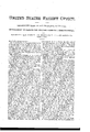
- the object of my invention is to provide a device for holding the wreath-pieces of staircase hand-rails in the proper angular position, to enable the workman to carry the. rail proply to the band or other saw for sawing the concave and convex sides of the pieces.
- Figure 1 is a perspective view Fig. 2 shows the method of laying out- A is the centralstandard or post which forms the support of the hand-rail.
- this post or standard I attach two or more adjustable spreading legs, b c, which have feet d 6.
- These legs can be shifted to any desired position around the post, and secured so that they can be moved out of the way of the work, and yet provide a base to steady the post when it is being handled by the workman.
- the lower end of the post is formed into a screw, and the legs I) e have each a ring, f, formed on the end opposite the feet, which is large enough to encircle and pass over the screw.
- Set-nuts g h serve to clamp them together when it is desired to hold them firmly in place.
- I place a cup-shaped annular wrench over the upper nut, the edge or rim of which is milled, so that the workman can readily loosen the upper nut, so as to shift the position of the legs and feet, and fasten them again.
- I is an adjustable collar, which is placed upon the post A, and which can be raised or lowered to any desired point, and secured by a set-screw, j.
- K L are the two parts of a hinge, which are connected together by a knuckle-joint at m.
- the part K of this hinge is a slotted plate, while the other part L consists of two parallel bars, in the length of each of which I make a bend, O, opposite each other, so that the two bends form a ring, which will pass down over the post A.
- the part or plate K of the hinge has a longitudinal slot, S, in it, as represented.
- An eccentric, t is secured upon one end of the pintle of the hinge, and is operated by a lever, u, so that by depressing the lever the eccentric is caused to bind against the end of the pintle, and holds the plate K and bars L firmly in the position to which it is adjusted before the lever is depressed.
- the standard A provided with adjustable legs I) c and feet (I e, and adjustable collar I, in combination with the hinge consisting of the slotted plate K and parallel bars L, said bars being arranged to be clamped to the standard A, and the eccentric t with its lever u, all combined and arranged to operate substantially as and for the purpose set forth.
Description
C.LAMB.
,CLAMPS FOR HOLDING HAND-RAIL WREATH PIECES.
No.185,111. Patented Dec.5,1876.
Witnesses TH E GRAPHIC CUN-Y- CHRISTOPHER LAMB, OF SAN FRANCISCO, CALIFORNIA.
IMPROVEMENT IN CLAMPS FOR HOLDING HAND-RAIL WREATH-PIECES.
Specification forming part of Letters Patent No. 185,11 1, dated December 5, 1876; application filed October 14, 1876.
To all whom it may concern Be it known that l, CHRISTOPHER LAMB, of the city and county of San Francisco and State ofCalifornia, have invented a device for holding hand-rail wreath-pieces while they are being sawed; and I do hereby declare the following to bea full, clear, and exact description thereof, reference being had to the accompanying drawings.
The object of my invention is to provide a device for holding the wreath-pieces of staircase hand-rails in the proper angular position, to enable the workman to carry the. rail proply to the band or other saw for sawing the concave and convex sides of the pieces.
Referring to the accompanying drawingin which Figure 1 is a perspective view Fig. 2 shows the method of laying out- A is the centralstandard or post which forms the support of the hand-rail. To the lower end of this post or standard I attach two or more adjustable spreading legs, b c, which have feet d 6. These legs can be shifted to any desired position around the post, and secured so that they can be moved out of the way of the work, and yet provide a base to steady the post when it is being handled by the workman. In the present instance, the lower end of the post is formed into a screw, and the legs I) e have each a ring, f, formed on the end opposite the feet, which is large enough to encircle and pass over the screw. Set-nuts g h, one above and one below these rings, serve to clamp them together when it is desired to hold them firmly in place. For convenience, I place a cup-shaped annular wrench over the upper nut, the edge or rim of which is milled, so that the workman can readily loosen the upper nut, so as to shift the position of the legs and feet, and fasten them again. I is an adjustable collar, which is placed upon the post A, and which can be raised or lowered to any desired point, and secured by a set-screw, j. K L are the two parts of a hinge, which are connected together by a knuckle-joint at m. The part K of this hinge is a slotted plate, while the other part L consists of two parallel bars, in the length of each of which I make a bend, O, opposite each other, so that the two bends form a ring, which will pass down over the post A. A
draw-screw, P, then draws the two ends of thebars together, so as to clamp them upon the post and fix them in position. The part or plate K of the hinge has a longitudinal slot, S, in it, as represented.
An eccentric, t, is secured upon one end of the pintle of the hinge, and is operated by a lever, u, so that by depressing the lever the eccentric is caused to bind against the end of the pintle, and holds the plate K and bars L firmly in the position to which it is adjusted before the lever is depressed.
The operation is as follows: When the j oints of the wreath have been made and the bevels applied, 1 cut a triangular piece from the lower corner of each wreath-piece W, so as to provide a flat portion for the lower end to rest upon. Then the collar must be adjusted on the standard so as to give the wreath-piece the required pitch, when its upper end is fastened to the plate K. The exact position to which the collar must be adjusted for each piece will be a matter of calculation for the stair-builder, and the manner of making this calculation is represented at Fig. 2, in which a represents the end of the piece. b represents the center of the hinge on. 0 represents a line drawn parallel with the end of the piece W through the center of the hinge. The point where this line intersects the top line of the rail represents the height on a perpendicular line, at which the collar is to be set. I then here a hole in the center of theupper square end of the piece W, and bolt the plate K to it by passing the bolt through the slot S at'the proper point to bring the upper edge of the plate on a line with the top of the rail. I then drop the bars L down upon the collar, and .tighten them by means of the screw P. The wreatlrpiece W'will then stand at the proper angle or pitch, so that by depressing the lever 10 the eccentric binds the hinge so as to hold the pin firmly, thus securing it in all of its adjustments to the standard A. The workman can now take the block and its holder and move them bodily, so as to carry the piece W to the saw and follow the curve of the inside and outside lines, which form the concave and convex sides of the wreath.
It will be readily seen that when the piece W is once properly adj ustedto the holder, the
band or other saw will give the proper vfaces to it on the proper lines. In adjusting the piece care must be taken, as above mentioned, to set the collar at the proper height to give the piece the correct pitch-that is, that one-half the diameter of the hinge be added to the length at the upper end of the wreath W, and a line drawn at this distance from the end of the piece parallel with the square end of the piece. The point where this line intersects the top line of the rail willindicate the height at which the collar is to be set-all as shown at Fig. 2.
Having thus described my invention, What I claim and desire to secure by Letters Patent, 1s-
The standard A, provided with adjustable legs I) c and feet (I e, and adjustable collar I, in combination with the hinge consisting of the slotted plate K and parallel bars L, said bars being arranged to be clamped to the standard A, and the eccentric t with its lever u, all combined and arranged to operate substantially as and for the purpose set forth.
In witness whereof I have hereunto set my hand and seal.
CHRISTOPHER LAMB. 14. s.]
Witnesses:
J. L. BOON-E, OLWYN T. STACY.
Publications (1)
| Publication Number | Publication Date |
|---|---|
| US185111A true US185111A (en) | 1876-12-05 |
Family
ID=2254516
Family Applications (1)
| Application Number | Title | Priority Date | Filing Date |
|---|---|---|---|
| US185111D Expired - Lifetime US185111A (en) | Improvement in clamps for holding hand-rail wreath-pieces |
Country Status (1)
| Country | Link |
|---|---|
| US (1) | US185111A (en) |
-
0
- US US185111D patent/US185111A/en not_active Expired - Lifetime
Similar Documents
| Publication | Publication Date | Title |
|---|---|---|
| US568543A (en) | Island | |
| US3982739A (en) | Portable vise | |
| US410414A (en) | Plumber s adjustable bracket | |
| US3124181A (en) | Clamp stop for saw fences | |
| US848837A (en) | Carpenter's floor-vise. | |
| US185111A (en) | Improvement in clamps for holding hand-rail wreath-pieces | |
| US413522A (en) | William a | |
| US947811A (en) | Clamp. | |
| US149654A (en) | Improvement in saw-tables | |
| US611713A (en) | Saw set and jointer | |
| US4353536A (en) | Miter clamp | |
| US415637A (en) | Mitering-iviachine | |
| US503050A (en) | Attachment for squares | |
| US718344A (en) | Compound bevel and square. | |
| US116256A (en) | Improvement in clapboard-gauges | |
| US789005A (en) | Saw-guide. | |
| US604574A (en) | Half to perley k | |
| US189831A (en) | Improvement in clamps for making frames | |
| US340802A (en) | Addison c | |
| US521802A (en) | Jeweler s anvil | |
| US375187A (en) | Saw-gage | |
| US622190A (en) | Saw-guide for sawing material for forming miter-joints | |
| US759023A (en) | Mitering and joining machine. | |
| US546964A (en) | Said richmond c | |
| US707307A (en) | Carpenter's tool. |