US18510A - Improvement in mowing-machines - Google Patents
Improvement in mowing-machines Download PDFInfo
- Publication number
- US18510A US18510A US18510DA US18510A US 18510 A US18510 A US 18510A US 18510D A US18510D A US 18510DA US 18510 A US18510 A US 18510A
- Authority
- US
- United States
- Prior art keywords
- bar
- cutter
- mowing
- machines
- wheel
- Prior art date
- Legal status (The legal status is an assumption and is not a legal conclusion. Google has not performed a legal analysis and makes no representation as to the accuracy of the status listed.)
- Expired - Lifetime
Links
- 239000004020 conductor Substances 0.000 description 2
- 230000004048 modification Effects 0.000 description 2
- 238000012986 modification Methods 0.000 description 2
- 244000025254 Cannabis sativa Species 0.000 description 1
- 238000010276 construction Methods 0.000 description 1
- 230000000694 effects Effects 0.000 description 1
- 230000003028 elevating effect Effects 0.000 description 1
- 238000004804 winding Methods 0.000 description 1
Images
Classifications
-
- A—HUMAN NECESSITIES
- A01—AGRICULTURE; FORESTRY; ANIMAL HUSBANDRY; HUNTING; TRAPPING; FISHING
- A01D—HARVESTING; MOWING
- A01D34/00—Mowers; Mowing apparatus of harvesters
- A01D34/01—Mowers; Mowing apparatus of harvesters characterised by features relating to the type of cutting apparatus
- A01D34/02—Mowers; Mowing apparatus of harvesters characterised by features relating to the type of cutting apparatus having reciprocating cutters
Definitions
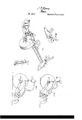
- Fig. 2 represents an end view ofthe same with the cutter-bar lowered close to the ground.
- Fig. 3 represents a similar end view with the cutter-bar raised up, and showing the changes ofthe several parts to effect the raising.
- Fig. 4 represents in perspective the outside dividing-shoe and supporting-wheel, and
- Fig. 5 represents a modification ot the plan of raising and' lowering the cutter-bar.
- my invention relates to the hanging or suspending of the cutter-bar by iiexible connections-such as cords or chainsby both its endsto rigid frames, so that it may be raised and lowered by both its ends at the same time by the driver in his seat, and without straining or twisting said cutter-bar, the advantages of so hanging the cutter being that the connection between the inner and outer part of the machine may be less heavy; the cutter-bar may be raised or lowered while it preserves the lsame horizontal plane and without warping or straining it; and, lastly, the iiexible connections will allow the cutterbar to rise when it comes against any obstruction and yield to it, when any rigid connection would, under the same circumstances, break or injure the machine.
- iiexible connections such as cords or chainsby both its endsto rigid frames
- A represents the main supporting and driving wheel, the journals of whose-axle B are supported by and turn in boxes a, (one only being seen, but both alike,) attached to the ⁇ frame C, so that said frame may hinge with or be raised or lowered on said journals.
- an arm D which has on its rear end a caster-wheel, E, to support it.
- the only object in its being a caster-wheel is to facilitate the turning around of the machine. Otherwise it might be a supporting-wheel alone.
- the cutter-bar F which may be ot' the usual length, and the outerend of said bar has attached to' it the divider G for dividing the grass or grain that is to be cut from that which is to he left standing'.
- an arm, H in the rear end of which is hung the outside supporting-wheel, I, said arm 'H passing through a guide, d, xed in the brace or post J.
- a groove or opening is made longitudinally through the cutter-bar F, in-which is laid or placed a rod or shaft, e, with proper supports in which it may freely'turn, and on this shaft e there is a pinion, f, into which a segmental rack, g, takes, said rack g being connected to a lever, K, pivoted to the top of the post or standard 'l1J and extending to the seat L, vso that the driver or conductor 'from his seat may with his hand or foot operate said lever, and through the segmental rack g and pinion fturn the shaft c in its supports or bearings.
- pulleys t' i' On each of the extreme ends of the cutterbar are arranged pulleys t' i', to the former, t', of which is connected one end of a cord or chain., 7c, the other end being attached to the arm D, and Vto the latter, i', is also connected one end ofa cord, l, the other end of which is attached to the arm H, so that when the shaft e is rotated in one direction it will by winding up the cords or chains on its pulleys raise up the cutter-bar, and by reversing lts motion, let the cutter-bar down again.
- I can dispense with the long shaft or rod running through the cutter-bar by using instead thereof a cord or chains, as will be explained in connection with Fig. 5.
- the standard or post h To the top ofv the standard or post h is attached one end of a radius-bar, M, the other end thereof being similarly connected-viz., pivoted to the standard N, which supports the driversv seat L.
- This bar M of course keeps the top of post h andthe standard N at the same relative distance from 'each other, and this, with the hinged joint in front ofthe cutterbar at c, holds the finger-bar (and the platform, when connected to it) horizontally with the ground, and admits of its risingor falling in the same horizontal plane, or planes that are parallel to each other.
- the cutter-bar is "in fact suspended at each one of its ends to a rigid frame-viz., the arln and wheel D E at one of its ends and the arm and wheel H I at its opposite endand said bar, being raised at both its ends simultaneously, does not sag, warp, or twist, and, being thus suspended and raised, itcan be made lighter, because it is not obliged to withstand so much strain.
- the standards N that support the seat L, are hinged as at n, because in raising thefraine G theboxes must roll somewhat; but the standards are braced from the arm l) by a brace, o, which keeps the seat in nearly the same position, and would do so entirely were the joint at b moved up to or made on the axle or iinmediately under the seat.
- a cord or chain, s has one of its ends attached to the plate Q, and then passes over a pulley, u, in the top of uprightpiece P, and thence down underneath or through a groove or opening in the cutter-bar to the opposite end thereof, where it may be wound up on the same pulley With the cord or chain atthat end, or by the raising-lever in any of the well-known ways.
- the cntter-bar is free to rise and surmount any intervening obstacle, and' thcn drop again to its adjusted height above the ground without the aid of the driver or conductor.
Landscapes
- Life Sciences & Earth Sciences (AREA)
- Environmental Sciences (AREA)
- Harvester Elements (AREA)
Description
UNITED STATES PATENT OFFICE.4
y JOHN P. MANNY, OF ROOKFORD, ILLINOIS.
IMPROVEMENT iN MowlNc-MACHINES.
Specification forming part of Letters Patent No. 18.516, dated October 27, 1857.
To all ufhom't'ft 'may concern: r
Be it known that I, JOHN P. MANNY, of Rockford, in the county of Winnebago and Stateof Illinois, have invented certain newand useful Improvements in `Mowing-Machines; and I do hereby declare the following to be a full, clear, and exact description ofthe same,
reference being had tothe accompanyingdrawings, making a part'thereof, in which- F igurel represents in perspective so much of a mowing-machine as will illustrate my invention. Fig. 2represents an end view ofthe same with the cutter-bar lowered close to the ground. Fig. 3 represents a similar end view with the cutter-bar raised up, and showing the changes ofthe several parts to effect the raising. Fig. 4 represents in perspective the outside dividing-shoe and supporting-wheel, and Fig. 5 represents a modification ot the plan of raising and' lowering the cutter-bar.
Similar letters of reference, where they occur in the several figures, denote like parts of the machine in all of them.
lhe nature ot' my invention relates to the hanging or suspending of the cutter-bar by iiexible connections-such as cords or chainsby both its endsto rigid frames, so that it may be raised and lowered by both its ends at the same time by the driver in his seat, and without straining or twisting said cutter-bar, the advantages of so hanging the cutter being that the connection between the inner and outer part of the machine may be less heavy; the cutter-bar may be raised or lowered while it preserves the lsame horizontal plane and without warping or straining it; and, lastly, the iiexible connections will allow the cutterbar to rise when it comes against any obstruction and yield to it, when any rigid connection would, under the same circumstances, break or injure the machine.
rIo enable others skilled. in the art to make and use my invention, I will proceed to describe the construction and operation of the same in connection with the drawings.
A represents the main supporting and driving wheel, the journals of whose-axle B are supported by and turn in boxes a, (one only being seen, but both alike,) attached to the `frame C, so that said frame may hinge with or be raised or lowered on said journals. To this frame-G is hinged at the point b, or at any other point nearer to the axle B, or to the axle itself, an arm D, which has on its rear end a caster-wheel, E, to support it. The only object in its being a caster-wheel is to facilitate the turning around of the machine. Otherwise it might be a supporting-wheel alone.
To the rear of the frame A is hinged by the hinges c c the cutter-bar F, which may be ot' the usual length, and the outerend of said bar has attached to' it the divider G for dividing the grass or grain that is to be cut from that which is to he left standing'.
To the divider is pivoted an arm, H, in the rear end of which is hung the outside supporting-wheel, I, said arm 'H passing through a guide, d, xed in the brace or post J.
A groove or opening is made longitudinally through the cutter-bar F, in-which is laid or placed a rod or shaft, e, with proper supports in which it may freely'turn, and on this shaft e there is a pinion, f, into which a segmental rack, g, takes, said rack g being connected to a lever, K, pivoted to the top of the post or standard 'l1J and extending to the seat L, vso that the driver or conductor 'from his seat may with his hand or foot operate said lever, and through the segmental rack g and pinion fturn the shaft c in its supports or bearings.
' On each of the extreme ends of the cutterbar are arranged pulleys t' i', to the former, t', of which is connected one end of a cord or chain., 7c, the other end being attached to the arm D, and Vto the latter, i', is also connected one end ofa cord, l, the other end of which is attached to the arm H, so that when the shaft e is rotated in one direction it will by winding up the cords or chains on its pulleys raise up the cutter-bar, and by reversing lts motion, let the cutter-bar down again.
I can dispense with the long shaft or rod running through the cutter-bar by using instead thereof a cord or chains, as will be explained in connection with Fig. 5.
To the top ofv the standard or post h is attached one end of a radius-bar, M, the other end thereof being similarly connected-viz., pivoted to the standard N, which supports the driversv seat L. This bar M of course keeps the top of post h andthe standard N at the same relative distance from 'each other, and this, with the hinged joint in front ofthe cutterbar at c, holds the finger-bar (and the platform, when connected to it) horizontally with the ground, and admits of its risingor falling in the same horizontal plane, or planes that are parallel to each other.
The cutter-bar is "in fact suspended at each one of its ends to a rigid frame-viz., the arln and wheel D E at one of its ends and the arm and wheel H I at its opposite endand said bar, being raised at both its ends simultaneously, does not sag, warp, or twist, and, being thus suspended and raised, itcan be made lighter, because it is not obliged to withstand so much strain.
The standards N, that support the seat L, are hinged as at n, because in raising thefraine G theboxes must roll somewhat; but the standards are braced from the arm l) by a brace, o, which keeps the seat in nearly the same position, and would do so entirely were the joint at b moved up to or made on the axle or iinmediately under the seat.
Fig. 5 represents a modification of the plan heretofore described for raising and lowering thecntterbar.` Itis as follows: I is the outside supporting-Wheel, hung to an upright piece, P. Two anges, r fr, are formed or turned on this piece P to form ways or guides for a plate, Q, totravel in, said plate being permanently attached to the end ofthe cutter-bar. A cord or chain, s, has one of its ends attached to the plate Q, and then passes over a pulley, u, in the top of uprightpiece P, and thence down underneath or through a groove or opening in the cutter-bar to the opposite end thereof, where it may be wound up on the same pulley With the cord or chain atthat end, or by the raising-lever in any of the well-known ways.
the constant attention of the driver, and the raising-lever can never be fastened, because of the liability of the bar to strike or come against obstructions on the ground, and if not allowed to rise itself to mount over such ob-A struction itis liable to break orbe injured.-
By the use of the flexible connections the cntter-bar is free to rise and surmount any intervening obstacle, and' thcn drop again to its adjusted height above the ground without the aid of the driver or conductor. j
Having thusl fully described the nature and object of my inventionwhat I claim therein as new, and desire to secure by Letters Patent; 1s-
Suspending, elevating, and lowering the cutter-barot mowing-machines in a horizontal position by means of iexible connections-such as cords or chainsattached to each of its ends, when the same are arranged in relation to and used iu combination with independent rigid frames, substantially in the manner and for the purposes herein described.
JOHN P. MANNY. Witnesses:
J As. B. WATTS. J. G. MANLOVE.
Publications (1)
| Publication Number | Publication Date |
|---|---|
| US18510A true US18510A (en) | 1857-10-27 |
Family
ID=2081885
Family Applications (1)
| Application Number | Title | Priority Date | Filing Date |
|---|---|---|---|
| US18510D Expired - Lifetime US18510A (en) | Improvement in mowing-machines |
Country Status (1)
| Country | Link |
|---|---|
| US (1) | US18510A (en) |
Cited By (2)
| Publication number | Priority date | Publication date | Assignee | Title |
|---|---|---|---|---|
| US20040162743A1 (en) * | 2003-02-19 | 2004-08-19 | Adam Thier | Horizontal enterprise planning in accordance with an enterprise planning model |
| US20040236738A1 (en) * | 2002-09-30 | 2004-11-25 | Adaytum, Inc. | Real-time aggregation of data within an enterprise planning environment |
-
0
- US US18510D patent/US18510A/en not_active Expired - Lifetime
Cited By (2)
| Publication number | Priority date | Publication date | Assignee | Title |
|---|---|---|---|---|
| US20040236738A1 (en) * | 2002-09-30 | 2004-11-25 | Adaytum, Inc. | Real-time aggregation of data within an enterprise planning environment |
| US20040162743A1 (en) * | 2003-02-19 | 2004-08-19 | Adam Thier | Horizontal enterprise planning in accordance with an enterprise planning model |
Similar Documents
| Publication | Publication Date | Title |
|---|---|---|
| US18510A (en) | Improvement in mowing-machines | |
| USRE6381E (en) | Improvement in mowing-machines | |
| USRE2294E (en) | Improvement in harvesters | |
| USRE563E (en) | Improvement in reel-supports in mowing-machines | |
| US17779A (en) | Improvement in harvesters | |
| USRE3525E (en) | Improvement in harvesters | |
| US25297A (en) | Improvement in harvesters | |
| US142111A (en) | Improvement in mowing-machines | |
| US78710A (en) | of cobby | |
| US20806A (en) | Improvement in harvesters | |
| US24700A (en) | Improvement in harvesters | |
| USRE3524E (en) | Improvement in harvesters | |
| US33862A (en) | Improvement in harvesters | |
| USRE2295E (en) | Improvement in harvesters | |
| USRE2453E (en) | Improvement in harvesters | |
| US20182A (en) | Improvement in harvesters | |
| US15252A (en) | Improvement in reaping and mowing machin | |
| US236209A (en) | beadley | |
| US588862A (en) | Harvester | |
| US1204356A (en) | Harvesting-machine. | |
| USRE2224E (en) | Improvement in harvesters | |
| US97556A (en) | Improvement in harvesters | |
| US120777A (en) | Improvement in harvester-rakes | |
| USRE3581E (en) | Improvement in harvesters | |
| US187493A (en) | Thieds his eight to english |