US1851095A - Folding photographic camera - Google Patents
Folding photographic camera Download PDFInfo
- Publication number
- US1851095A US1851095A US309494A US30949428A US1851095A US 1851095 A US1851095 A US 1851095A US 309494 A US309494 A US 309494A US 30949428 A US30949428 A US 30949428A US 1851095 A US1851095 A US 1851095A
- Authority
- US
- United States
- Prior art keywords
- box
- carrying frame
- recess
- lens
- lens carrying
- Prior art date
- Legal status (The legal status is an assumption and is not a legal conclusion. Google has not performed a legal analysis and makes no representation as to the accuracy of the status listed.)
- Expired - Lifetime
Links
- 238000010276 construction Methods 0.000 description 3
- 230000000063 preceeding effect Effects 0.000 description 3
- 235000013929 Psidium pyriferum Nutrition 0.000 description 1
- 244000236580 Psidium pyriferum Species 0.000 description 1
- 230000003100 immobilizing effect Effects 0.000 description 1
- 230000003287 optical effect Effects 0.000 description 1
- 238000005192 partition Methods 0.000 description 1
Images


Classifications
-
- G—PHYSICS
- G03—PHOTOGRAPHY; CINEMATOGRAPHY; ANALOGOUS TECHNIQUES USING WAVES OTHER THAN OPTICAL WAVES; ELECTROGRAPHY; HOLOGRAPHY
- G03B—APPARATUS OR ARRANGEMENTS FOR TAKING PHOTOGRAPHS OR FOR PROJECTING OR VIEWING THEM; APPARATUS OR ARRANGEMENTS EMPLOYING ANALOGOUS TECHNIQUES USING WAVES OTHER THAN OPTICAL WAVES; ACCESSORIES THEREFOR
- G03B17/00—Details of cameras or camera bodies; Accessories therefor
- G03B17/02—Bodies
- G03B17/04—Bodies collapsible, foldable or extensible, e.g. book type
Definitions
- My invention consists in providing a folding photographic apparatus of the type indicated in which a rigid plate carries two pivot shafts on which turn respectively the lens carrying frame and the box of the apparatus containing the supply of plates or films.
- the position of the two pivot shafts is so arran 'ed that when the lens carrying frame and the box abut against the rigid plate which carries them and constitutes the cover of the box, the lens carrying frame enters a recess provided for that purpose in the upper part of the box.
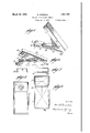
- FIG. 1 is an elevational side view of the apparatus wide open
- Fig. 2 is a. front view of the apparatus in the same position
- Fig. 3 is an elevational side view of the apparatus at the beginning of the folding operation;
- Y Fig. 4 is a similar view with the lens carrying frame in the folded position;
- Figs. '5 and 6 are ierspeetive views showing the apparatus in a further state of folds
- Fig; 7 is a diagrammatic view of the apparatus entirely folded showing thetposition of the bellows; 50
- Fig.8 is a front view of the folded apparatus, the front plate being supposed to be removed;
- Fig. 9 is a corresponding back view with the back plate removed
- Fig. 10 is a development of the bellows
- Figs. 11 and 12 are diagrammatic views showing in perspective the rear part of the bellows in a half folded position.
- my apparatus is provided with a rigid plate 4, pivoted at 24c to the box 1 of the apparatus.
- the lens carrying frame 2 On said plate is pivoted ate, the lens carrying frame 2.
- the box of theapparatus is provided with a space serfvlng as a recess for the lens when the apparatus is folded up.
- the plate or film is placed in the recess 3 of the box.
- In the box 1 is likewise provided a space 16 for receiving the folded bellows.
- Fig. 1 shows the position which the ens occupies-with respect to the case when he bOX is open.
- he lens carrying frame 2 is'first folded back gainst the plate by a movement of rotas tion, as shownin Fig. 8 so as to finally, occupy the position of l, the whole being then swung about the shaft 24 a'ssh own in Figs. 5 and 6.
- the elements then occupy the'position s iown Figs. 7 to 9 inclusive, the lens carrying frame 2 entering thespace 25 provided in the box so that the thickness of the closed apparatus becomes reduced to that of the box itself.
- connection between the rigid plate l, the lens carrier and the box form no particular part of my invention and may be. composed of any'of the well known expedients known in the art.
- the lens carrying frame and the box are arranged independently and are connected to the rigid plate 4 by means of connecting elements 7, ,8, and 9, 10 of well known type, for immobilizing the lens carrying frame, and the plate in operative p0S1t10I1
- a special type of bellows must be provided for the apparatus in order that the same may enter the recess 16 provided in the front part of the frame.
- 10 I have illustrated a type of bellows for use with an a-ppa-ratus of 9 to 12 centimeters in size with a focal length of 142 millimeters- It is 'to be under- 4 mension of the lens; 6 the thickness of the lens; a the distance from the sensitive plate to the edge of the frame; and clthe distance from the axis of rotation of the box to the internal surface of the partition separating the plate chamber from the lens receiving recess with respect to the side provided with that recess.
- RN is drawn equal to RM.
- the upper face L W I. I is easily constructed when it is considered that the part L N C Cis identical to the part M N E D of the lower surface.
- the second lateral surface is identical to the surface I J M L and is constructed according to the dimensions thereof.
- the third plait is parallel tothe two first. ones and situated in the middle of the interval J Z. r a
- U pper surface L W I [.'The plaits 1/3 and C C are determined frornlthe preceeding constructions.
- the intermediate plait between FK and CC is parallel to the preceeding ones and'is situated in the middle of the interval KC.
- the plaits F1 and K1 are thediagonals of the trapeziumrK F II.
- the plait YY is parallel to H and passes through the po nt above I of intersection of the two diagonals mentioned.
- the plaits are indicated in Fig. 10 bydot and dash lines.
- the spaces between the plaits are reinforced with thin cardboard as indicated' in the figure.
- the space I J C D must be left flexible;
- a photographic apparatus comprising in combination a box provided with a recess in its upper part, a chamber provided in said box below said recess, and adapted to carry the light sensitive elements, a rigid cover plate hinged to the lower front part of said box, a lens carrying frame pivotally mounted on the inner side of said cover plate at a distance from the free end thereof that is subtantially equal to the height of said lens carrying frame, said lens carrying frame being adapted to be swung against said free end whereby it may engage the aforesaid recess in the box when the cover plate is swung into the closed position against the front part of the box.
- a photographic apparatus comprising in combination a box provided with a recess in its upper part, a chamber provided in said box below said recess and adapted to carry the light sensitive elements, a rigid cover plate hinged to the lower front part of said box, means for holding said cover plate in operative position, a lens carrying frame pivotally mounted on the inner side of said cover plate at a distance from the free end thereof substantially equal to the height of said lens carr ing' frame, said lens carr in frame being adapted to be swung against said free end whereby it may engage the aforesaid recess in the box when the cover plate is swung into the closed position against the front part of the box.
- a photographic apparatus comprising in combination a box provided with a recess in its upper part, a chamber provided in said box below said recess and adapted to carry the light sensitive elements, a rigid cover plate hinged to the lower front part of said box, means for holding said cover in a given angular relation with respect to said box, a
- ⁇ - lens carrying frame pivotally mounted on the inner side of said cover plate at a distance from the free end thereof substantially equal to the height of said lens carrying frame, said lens carrying frame being adapted to be swung against said free end whereby it may engage the aforesaid recess in the box when the cover plate is swung into the closed position against the front part of the box, and means for holding said lens carrying frame in an angular relation with respect to said cover plate equal to the above mentioned angular relation of the cover plate with respect to the box, whereby in the open posltion of the apparatus, the lens carrying frame I is parallel to the box.
- a photographic apparatus of the type described comprising in combination a box provided with a recess in its upper part, a plate chamber provided in said box below said recess, a rigid cover plate hinged to the lower front part of said box, a lens carrying frame pivotally mounted on the inner side of said cover plate at a distance from the free end thereof substantially equal to the height of said lens carrying frame, said lens carrying frame being adapted to be swung against said free end whereby it may engage the aforesaid.
- recess in the box when the cover plate isswung into theclosed position against the front part of the box a bellows interconnectingsaid box and said lens carrying frame, and a chamber formed in said box in front of the plate chamber.
- photographic apparatus comprising in combination box provided with a recess at its upper part, a plate chamber provided in said box below said recess, a rigid cover plate hinged to the lower front partof said box, ineansfor holding said cover in a given angular relation with respect to said box, a lens carrying frame pivotally mounted on the inner side of said cover plate at a distance from the free end thereof substantially equal to the height of said lens carrying frame, said lens carrying frame being adapted to be swung against said free end whereby it may engage the aforesaid recess in the box when the cover plate is swung into the closed position against the front part of the box, means for holding said lens carrying frame in an angular relation with respect to said cover plate similar to the above mentioned angular relation of the cover plate with respect to the box, whereby in the open position of ti apparatus, the lens carrying frame is parallel to the box, a bellows interconnecting said box and said lens carrying frame, and a chamber formed in said box in front of said plate chamber adapted
- a photographic apparatus comprising in combination a rigid plate, a lens carrying frame and a box both pivoted on said plate about parallel axes r spectively and adapted to be swung against said plate, said box being provided with a shallow recess having the same shape as the lens carrying frame and adapted to receive it when said frame and said box are both swung against the rigid plate, and a bellows for connecting said lens carrying frame to said box.
- A. foldable camera structure comprising two rigid rectangular frames and a bellows connecting them, said bellows consisting of two opposite sides, a top and a bottom, the top being provided with a first transverse crease, three transverse creases close to each other, two diagonal creases connecting the ends of the last of said three creases to the front corners of said top and a transverse crease passing through the point of intersection of said diagonal creases, the bottom being provided with four transverse creases located in the front part thereof and rather close to each other, and the opposite sides being provided each with a wholly flexible part Connecting the part of the top extending between the front edge thereof and the first of the three above mentioned adjacent 5 transverse creases in said top to the part of the bottom extending between the front edge thereof and the first 0f the four above men tioned adjacent creases in said bottom, and with a plaited part comprising a substantial- 1y axial longitudinal crease extending from 7 said flexible part to a point located at acertain distance from the rear
Landscapes
- Physics & Mathematics (AREA)
- General Physics & Mathematics (AREA)
- Structure And Mechanism Of Cameras (AREA)
Description
March 29, 1932. M. GOSSELIN FOLDING PHOTOGRAPHIC CAMERA Filed Oct. 1. 1928 3 Sheets-Sheet 1 March 29, M UN FOLDING PHOTOGRAPHIC CAMERA Filed Oct. 1, 1928 5 Sheets-Shet 2' Patented Mar. 29, 1932 IEARCEL GOSSELIN, F SOUSSE, TUNIS FOLDING PHOTOGRAPHIC CAMERA- Application filed. Gctober '1, 1928, Serial No. 309,494, and in the lens is displaced parallel to itself by sliding it along the optical axis thereof, in such a way as to approach the box against which it abuts.
Obviously such an arrangement necessitates considerable bulkiness in thickness when ness of the film or plate su o l as n L the apparatus is provided with a supply of plates or plane films.
My invention consists in providing a folding photographic apparatus of the type indicated in which a rigid plate carries two pivot shafts on which turn respectively the lens carrying frame and the box of the apparatus containing the supply of plates or films. The position of the two pivot shafts is so arran 'ed that when the lens carrying frame and the box abut against the rigid plate which carries them and constitutes the cover of the box, the lens carrying frame enters a recess provided for that purpose in the upper part of the box. Thus, when the apparatus is closed, its bulkiness is reduced,
due to the "fact that the thickness of the lens carrier is no longer added to the thickis the case in apparatus in current use.
ence to the accompanying drawings in con- V The invention further contemplates a constructional embodiment of a bellows which is particularly suitable for use with apparatus of thetype indicated, the said'bellows being adapted to enter a recess, also provided inthe box, when the apparatus is closed.
The invention will be more readily understood by those skilled in'the art with refernection with the following description.
In th drawings- Fig. 1 is an elevational side view of the apparatus wide open;
Fig. 2 is a. front view of the apparatus in the same position;
Fig. 3 is an elevational side view of the apparatus at the beginning of the folding operation; Y Fig. 4 is a similar view with the lens carrying frame in the folded position;
Germany November 17, 1927.
Figs. '5 and 6 are ierspeetive views showing the apparatus in a further state of folds;
In the two last mentioned figures the creases in the front part of the bellows adja- 55 cent the carrying frame have not been shown indetail for the sake of clearness;
Fig; 7 is a diagrammatic view of the apparatus entirely folded showing thetposition of the bellows; 50
Fig.8 is a front view of the folded apparatus, the front plate being supposed to be removed;
Fig. 9 is a corresponding back view with the back plate removed;
Fig. 10 is a development of the bellows;
Figs. 11 and 12 are diagrammatic views showing in perspective the rear part of the bellows in a half folded position.
In all these figures, the creases are indicated by dot and dash lines.
Referring to the drawings more in detail, my apparatus is provided with a rigid plate 4, pivoted at 24c to the box 1 of the apparatus. On said plate is pivoted ate, the lens carrying frame 2. The box of theapparatus is provided with a space serfvlng as a recess for the lens when the apparatus is folded up. The plate or film is placed in the recess 3 of the box. In the box 1 is likewise provided a space 16 for receiving the folded bellows.
Fig. 1" shows the position which the ens occupies-with respect to the case when he bOX is open. In closing the apparatus, he lens carrying frame 2 is'first folded back gainst the plate by a movement of rotas tion, as shownin Fig. 8 so as to finally, occupy the position of l, the whole being then swung about the shaft 24 a'ssh own in Figs. 5 and 6. The elements then occupy the'position s iown Figs. 7 to 9 inclusive, the lens carrying frame 2 entering thespace 25 provided in the box so that the thickness of the closed apparatus becomes reduced to that of the box itself.
The connections between the rigid plate l, the lens carrier and the box form no particular part of my invention and may be. composed of any'of the well known expedients known in the art. Preferably, as shown in Fig. 8, the lens carrying frame and the box are arranged independently and are connected to the rigid plate 4 by means of connecting elements 7, ,8, and 9, 10 of well known type, for immobilizing the lens carrying frame, and the plate in operative p0S1t10I1 Obviouslyfrom the foregoing a special type of bellows must be provided for the apparatus in order that the same may enter the recess 16 provided in the front part of the frame. In Fig. 10 I have illustrated a type of bellows for use with an a-ppa-ratus of 9 to 12 centimeters in size with a focal length of 142 millimeters- It is 'to be under- 4 mension of the lens; 6 the thickness of the lens; a the distance from the sensitive plate to the edge of the frame; and clthe distance from the axis of rotation of the box to the internal surface of the partition separating the plate chamber from the lens receiving recess with respect to the side provided with that recess.
Adverting to Fig. 10 with these assumptions in view, we have the following relations By giving (5,6,1. h, e, e and a suitable values, all the data necessary for construction of the bellows is complete and the same may be established in the followingmanner: f rectangle is first constructed with LM as abas'e, LM being equal to b 5 mm. and the side perpendicular thereto (shown in dotted lines) being equal to MN a; Fromthe mid dle B of LM a length equal to Z is measured, which gives the point P.
At P a perpendicular is erected on LM and on thisline PC is laid off equal to it.
From the point C as a center with a radius equalto CD =2 Z+ (ee) an arc is describedQ J From the point M as a center with a radius equal to MD=cZ a second arc is described.
The intersection of the two arcs determines the POlIlt.D.* i v ,On a prolongation of the side LC, CI is I laid off equal to Z+e+e mm.
Withthe point I as a center and a radius equal to IJ=2 Z-3, an arc is described which cuts the prolongation of side MD at J.
The lateral surface I J M L of the bellows is thus established.
v ith the point M as a center and aradius equal to MR=a/2 an arc is described, and from the point D as a center with a'radius equal to 'DG=a/24 mm. a second arc is described and RG is drawn tangent to the two arcs at points E and G. V
On a prolongation of theline MR, RN is drawn equal to RM.
()na prolongation of the line DG, is drawnequal GD.
From the point J line is drawn parallel to the side MN which cuts a prolongation of the side'llE at V.
The lower surface M N V J of the bellows is thus established. a e
The upper face L W I. I is easily constructed when it is considered that the part L N C Cis identical to the part M N E D of the lower surface. I
To complete the construction it is merely necessary to draw II parallel to L W.
The second lateral surface is identical to the surface I J M L and is constructed according to the dimensions thereof.
I (Jonstmctc'mt 0f plaits Lower surface M N V J .The plait DE is already established and the plait HZ is parallel to said first plait and at a distance HG=e'2 mm.
The third plait is parallel tothe two first. ones and situated in the middle of the interval J Z. r a
. Lateral swfaces.The' plait B B joins the middle points B and B of the sides LM and 1 CD. The point 0 is determined by the intersection of the diagonals-of the parallelogram L ML 1 and establishes the plaits L O.
and-M O. p K
The pla t L O is determined by LL=LB. U pper surface L W I [.'The plaits 1/3 and C C are determined frornlthe preceeding constructions. The plaitFK is parallel to the preceeding ones and itslposit on is determined by KG=@2 mmg The intermediate plait between FK and CC is parallel to the preceeding ones and'is situated in the middle of the interval KC.
The plaits F1 and K1 are thediagonals of the trapeziumrK F II. The plait YY is parallel to H and passes through the po nt above I of intersection of the two diagonals mentioned.
The plaits are indicated in Fig. 10 bydot and dash lines. The spaces between the plaits are reinforced with thin cardboard as indicated' in the figure. The space I J C D must be left flexible;
Having described my. invention what I claim as new and desire to secure by Letters Patent is:
1. A photographic apparatus comprising in combination a box provided with a recess in its upper part, a chamber provided in said box below said recess, and adapted to carry the light sensitive elements, a rigid cover plate hinged to the lower front part of said box, a lens carrying frame pivotally mounted on the inner side of said cover plate at a distance from the free end thereof that is subtantially equal to the height of said lens carrying frame, said lens carrying frame being adapted to be swung against said free end whereby it may engage the aforesaid recess in the box when the cover plate is swung into the closed position against the front part of the box.
2. A photographic apparatus comprising in combination a box provided with a recess in its upper part, a chamber provided in said box below said recess and adapted to carry the light sensitive elements, a rigid cover plate hinged to the lower front part of said box, means for holding said cover plate in operative position, a lens carrying frame pivotally mounted on the inner side of said cover plate at a distance from the free end thereof substantially equal to the height of said lens carr ing' frame, said lens carr in frame being adapted to be swung against said free end whereby it may engage the aforesaid recess in the box when the cover plate is swung into the closed position against the front part of the box.
3. A photographic apparatus comprising in combination a box provided with a recess in its upper part, a chamber provided in said box below said recess and adapted to carry the light sensitive elements, a rigid cover plate hinged to the lower front part of said box, means for holding said cover in a given angular relation with respect to said box, a
\- lens carrying frame pivotally mounted on the inner side of said cover plate at a distance from the free end thereof substantially equal to the height of said lens carrying frame, said lens carrying frame being adapted to be swung against said free end whereby it may engage the aforesaid recess in the box when the cover plate is swung into the closed position against the front part of the box, and means for holding said lens carrying frame in an angular relation with respect to said cover plate equal to the above mentioned angular relation of the cover plate with respect to the box, whereby in the open posltion of the apparatus, the lens carrying frame I is parallel to the box.
4. A photographic apparatus of the type described comprising in combination a box provided with a recess in its upper part, a plate chamber provided in said box below said recess, a rigid cover plate hinged to the lower front part of said box, a lens carrying frame pivotally mounted on the inner side of said cover plate at a distance from the free end thereof substantially equal to the height of said lens carrying frame, said lens carrying frame being adapted to be swung against said free end whereby it may engage the aforesaid. recess in the box when the cover plate isswung into theclosed position against the front part of the box, a bellows interconnectingsaid box and said lens carrying frame, and a chamber formed in said box in front of the plate chamber.
photographic apparatus comprising in combination box provided with a recess at its upper part, a plate chamber provided in said box below said recess, a rigid cover plate hinged to the lower front partof said box, ineansfor holding said cover in a given angular relation with respect to said box, a lens carrying frame pivotally mounted on the inner side of said cover plate at a distance from the free end thereof substantially equal to the height of said lens carrying frame, said lens carrying frame being adapted to be swung against said free end whereby it may engage the aforesaid recess in the box when the cover plate is swung into the closed position against the front part of the box, means for holding said lens carrying frame in an angular relation with respect to said cover plate similar to the above mentioned angular relation of the cover plate with respect to the box, whereby in the open position of ti apparatus, the lens carrying frame is parallel to the box, a bellows interconnecting said box and said lens carrying frame, and a chamber formed in said box in front of said plate chamber adapted to receive said bellows in the folded position.
6. A photographic apparatus comprising in combination a rigid plate, a lens carrying frame and a box both pivoted on said plate about parallel axes r spectively and adapted to be swung against said plate, said box being provided with a shallow recess having the same shape as the lens carrying frame and adapted to receive it when said frame and said box are both swung against the rigid plate, and a bellows for connecting said lens carrying frame to said box.
7. A. foldable camera structure comprising two rigid rectangular frames and a bellows connecting them, said bellows consisting of two opposite sides, a top and a bottom, the top being provided with a first transverse crease, three transverse creases close to each other, two diagonal creases connecting the ends of the last of said three creases to the front corners of said top and a transverse crease passing through the point of intersection of said diagonal creases, the bottom being provided with four transverse creases located in the front part thereof and rather close to each other, and the opposite sides being provided each with a wholly flexible part Connecting the part of the top extending between the front edge thereof and the first of the three above mentioned adjacent 5 transverse creases in said top to the part of the bottom extending between the front edge thereof and the first 0f the four above men tioned adjacent creases in said bottom, and with a plaited part comprising a substantial- 1y axial longitudinal crease extending from 7 said flexible part to a point located at acertain distance from the rear frame, and three creases extending from said point respective} ly to the end of the first mentioned transverse crease in the top and to the top and the bottom corners of the rear frame.
In testimony that I claim the foregoing as my invention, I have signed my name.
- MARCEL GOSSELIN.
Applications Claiming Priority (1)
| Application Number | Priority Date | Filing Date | Title |
|---|---|---|---|
| DE1851095X | 1927-11-17 |
Publications (1)
| Publication Number | Publication Date |
|---|---|
| US1851095A true US1851095A (en) | 1932-03-29 |
Family
ID=7746010
Family Applications (1)
| Application Number | Title | Priority Date | Filing Date |
|---|---|---|---|
| US309494A Expired - Lifetime US1851095A (en) | 1927-11-17 | 1928-10-01 | Folding photographic camera |
Country Status (1)
| Country | Link |
|---|---|
| US (1) | US1851095A (en) |
Cited By (5)
| Publication number | Priority date | Publication date | Assignee | Title |
|---|---|---|---|---|
| US3706267A (en) * | 1971-06-18 | 1972-12-19 | Eastman Kodak Co | Camera bellows |
| US3877047A (en) * | 1973-12-28 | 1975-04-08 | Polaroid Corp | Folding camera and bellows |
| US3955207A (en) * | 1974-04-25 | 1976-05-04 | Eastman Kodak Company | Camera bellows |
| US4006488A (en) * | 1974-09-05 | 1977-02-01 | Fuji Photo Film Co., Ltd. | Bellows for use in a foldable camera |
| US4241986A (en) * | 1979-08-10 | 1980-12-30 | Eastman Kodak Company | Folding camera |
-
1928
- 1928-10-01 US US309494A patent/US1851095A/en not_active Expired - Lifetime
Cited By (5)
| Publication number | Priority date | Publication date | Assignee | Title |
|---|---|---|---|---|
| US3706267A (en) * | 1971-06-18 | 1972-12-19 | Eastman Kodak Co | Camera bellows |
| US3877047A (en) * | 1973-12-28 | 1975-04-08 | Polaroid Corp | Folding camera and bellows |
| US3955207A (en) * | 1974-04-25 | 1976-05-04 | Eastman Kodak Company | Camera bellows |
| US4006488A (en) * | 1974-09-05 | 1977-02-01 | Fuji Photo Film Co., Ltd. | Bellows for use in a foldable camera |
| US4241986A (en) * | 1979-08-10 | 1980-12-30 | Eastman Kodak Company | Folding camera |
Similar Documents
| Publication | Publication Date | Title |
|---|---|---|
| US2367967A (en) | Animated picture device | |
| US2246920A (en) | Variable photographic mask for maintaining constant proportions of a visible area | |
| US1851095A (en) | Folding photographic camera | |
| US2245999A (en) | Folding partition for luggage | |
| US3541599A (en) | Container | |
| SE8103780L (en) | FILTER INSERT OF FOLDED FILTER MATERIAL TO FILTER FOR FLOATING MATERIAL AND A SET FOR ITS MANUFACTURING | |
| US2768554A (en) | Optical device of foldable material | |
| US1528621A (en) | Color-sample book | |
| US4443198A (en) | Folding board for pamphlets, maps and the like | |
| US4549785A (en) | Stereo viewer | |
| US2934999A (en) | Foldable stereoscopic viewer | |
| US3277781A (en) | Tri-fold rear projection screen | |
| US1958192A (en) | Color match guide | |
| US2615732A (en) | Map capable of being folded together and spread flat again | |
| US2662442A (en) | Collapsible picture viewing device | |
| US1932464A (en) | Lantern slide holder | |
| US1595997A (en) | Optical apparatus containing films | |
| US2377109A (en) | Viewer | |
| US2692530A (en) | Picture viewing device | |
| US2944356A (en) | Transparency equipment | |
| US4054191A (en) | Carrying case for toys, dolls, or the like | |
| US2403747A (en) | Microfilm reader | |
| US2311946A (en) | Process and device for the representation of objects | |
| US396573A (en) | Camera-carrying case and plate-changing box | |
| US477337A (en) | Photographic film-holder |