US1851092A - Transmission delay circuits - Google Patents
Transmission delay circuits Download PDFInfo
- Publication number
- US1851092A US1851092A US252831A US25283128A US1851092A US 1851092 A US1851092 A US 1851092A US 252831 A US252831 A US 252831A US 25283128 A US25283128 A US 25283128A US 1851092 A US1851092 A US 1851092A
- Authority
- US
- United States
- Prior art keywords
- condensers
- brush
- electrical
- commutator
- charges
- Prior art date
- Legal status (The legal status is an assumption and is not a legal conclusion. Google has not performed a legal analysis and makes no representation as to the accuracy of the status listed.)
- Expired - Lifetime
Links
- 230000005540 biological transmission Effects 0.000 title description 12
- 230000011664 signaling Effects 0.000 description 11
- 230000000875 corresponding effect Effects 0.000 description 7
- 238000007599 discharging Methods 0.000 description 3
- 238000004804 winding Methods 0.000 description 3
- 230000003247 decreasing effect Effects 0.000 description 2
- 238000006073 displacement reaction Methods 0.000 description 2
- 238000000034 method Methods 0.000 description 2
- 230000010355 oscillation Effects 0.000 description 2
- 241000370685 Arge Species 0.000 description 1
- 101100517651 Caenorhabditis elegans num-1 gene Proteins 0.000 description 1
- 101100285518 Drosophila melanogaster how gene Proteins 0.000 description 1
- 125000002059 L-arginyl group Chemical group O=C([*])[C@](N([H])[H])([H])C([H])([H])C([H])([H])C([H])([H])N([H])C(=N[H])N([H])[H] 0.000 description 1
- 101100168115 Neurospora crassa (strain ATCC 24698 / 74-OR23-1A / CBS 708.71 / DSM 1257 / FGSC 987) con-6 gene Proteins 0.000 description 1
- 101150014691 PPARA gene Proteins 0.000 description 1
- 238000006243 chemical reaction Methods 0.000 description 1
- 230000007423 decrease Effects 0.000 description 1
- 230000001934 delay Effects 0.000 description 1
- 230000000694 effects Effects 0.000 description 1
- 239000003471 mutagenic agent Substances 0.000 description 1
- 230000008054 signal transmission Effects 0.000 description 1
Images
Classifications
-
- H—ELECTRICITY
- H03—ELECTRONIC CIRCUITRY
- H03H—IMPEDANCE NETWORKS, e.g. RESONANT CIRCUITS; RESONATORS
- H03H19/00—Networks using time-varying elements, e.g. N-path filters
- H03H19/002—N-path filters
Definitions
- tOlIOtIOdHCG time delayin accordancewith the principles of the invenmutator about its axis and to-thereby pro-f1 tion is to associate with a commutator a number of brushes of a'typ'e to be subsequently I described, one of which is connected to the electrical source or input circuit," and another one of which ls'connected to the-translating or amplifylng device or'output clrcuit.
- a third brush may,
- Fig. 2 represents'another embodiment of the invention, in which the disk or commutator is stationary and thebrushes rotatable with respect tolthe. disk or commutator.
- a microphone S in series relationship with a batteryG so that speech Varia-- 'tions may be translated into corresponding electrical variationsf
- These electrical varia-' tions are then impressed upon an amplifier Afo f any'well-known type, preferably of-a vacuum tube type, amplifier amplifying the electrical variations corresponding to the speech impinging upon the microphones.
- the amplifier currents are then transmitted through I a transformer T to' a brush B which is connected to ground through a resistance R andithesecondary winding of transformer T The .brushlB is associated.
- a commutator or rotatable disk ,K hav- 7 mg a plurality of. segmentseach of which acts; like a; condenser in its capacity to ground.
- Some of these condensers are designated by the reference character C.
- Two other brushes, B and B are similarly associated with the commutator K.
- the com- .mutator K revolves about its axis its segcorresponding variations in the current flowing between'the plate and filament of that .of the segments of thelcommutator is conbrush B which receives the charge and transmits it to an output circuit, as will be described more fully hereinafter.
- the third brush B short-circuits each of the condens ers through a resistance R as each condenser passes brush B .
- the electricalcharges. which are surrendered to the brush; 13 as a result of the rotation of the commutator K cause variations in the potential impressed across a resistance R Accordingly, corresponding potential variations are effected between the grid and filament of a three-electrode vacuum tube V, which may be employed in this invention to act as an amplifier.
- the resistance This in series with a battery G between the grid and filament of vacuum tube V, and these ele- I ments provide the bias necessary for the proper operation of vacuum tube V as an A amplifier.
- the filament of the vacuum tube V is heated to an electron emitting tempera- 'ture by the flow-of current from a battery C
- the potential variations between the grid and filament of the vacuum tube V produce vacuum tube, the circuit interconnecting the plate and filament including the primary winding of a transformer T and a battery
- These amplified current variations are then transmitted through the transformer T "toan electrical wave filter F which may be of any well-known type, preferably of the type described in the patent to G. A. Campbell, No. 1,227,113, dated May 22, 191?.
- the electrical wave filter F preferably freely transmits currents of frequencies below a :definite limit, while substantially suppressing currents of frequencies above that definite limit. Currents of frequencies above the :definite limit may be considered distortions,
- F ig. 2 shows another embodiment of the inventlon. 1n which the commutator K is malnt'amed' 1n.a stat onary posit on. Each nected to a separate condenser C. These condensers are preferably of the same capacity and have one terminal in common. Sliprings SR SR and SR rotate about a neednot be repeated.
- the operationof the apparatus of F ig. 2 will now be briefly described, it being understood that the general principles of the operation may be applied equally well to the apparatus of Fig. 1.
- the output of the amp1ifier A is transmitted through transformer T and through a resistance R slip-ring SR and brush-holder Hi to brush B Since brush-holder H is pinned or otherwise permanently. fastened to the slip-ring SR brush B, will rotate about the common axis at the same speed and progressively make contact with the various condensers C.
- the entire potential transmitted by the amplifier A through transformer T is not impressed uponeach condenser C because of the presence of the resistance R Resistance R decreases each voltage by a definite amount, though these decreased Voltages correspond in every respect to the voltages transmitted by the amplifier A.
- Brush B rotates at the same speed as brush B and about the same axis though having an angular. displacement with respect to brush B the angular displacement determining the time delay to be effected by the apparatus, Brush B picks up the charges of the various condensers in the same progression in which they were charged and impresses corresponding voltages across the terminals of the resistance R and'between the grid and filament of the vacuum tube V.
- Brush B follows brush B brush B being held by brush-holder H which is similarly pinned or otherwise fastened to the slip-ring SR Brush B short-circuits each each condenser in' proper condition to receive an electrical charge and thereafter to surrender it.
- the resistance R is of a suitable magnitude to thereby prevent the circuits associated with the vacuum tube V from sustaining oscillations If each condenser were short-circuited without series resistance the tendency for the produccondenser through the resistance R thereby placing ,lybelverygreat.
- a commutator two feet in di- 1 ameter having Qcommutator segments.v about vone-sixteenth of an inch in width,:separ ated .by very small distances. v Such a commutator would, accordingly, have approximately 1,2 ,segments in its circumference. If it be assumed that the commutator is stationary l and that the brushes. rotate ten revolutions per second,-i. e.,'6 )0 revolutions per. minute, then each brush would in effect pass 12,000
- each condenser would be passed'by-each brush tentimes per second; With such a commutator andwithsucha brush speed, it will be apj-isfactorytransmission could be conveniently attained .overa band of 4!,000'01 5,000'cycles.
- the maxlmum delay attainable would I ,beonafifteenth of a second, etc. ,Ifit-becomes desirable to obtain :delays which are greaterthan the max1mum,'then two or more of these arrangements m ght be connected 111 l tandem, or, on the other hand, a greater num- 1 vber. ofsegments-might be provided on each rother characteristic of the electrical circuit commutator, as by making thesesegments narrower or by increasing thediameter of the commutator. Obviously, by, changing" the brush speedgthe maximum delay attainable may be correspondingly changed within practicallimits. Ingeneral, the interval of time delay is decreased as the brush speed is increased, and vice versa.
- each voltage transmitted by the amplifier A to each of the condensers passes through the resistance R If it be assumedthat there exist the ideal conditions'of no leakage and no inductance, then the voltage impressed across each condenser will be i in which E is the voltage output of the amplifier A, B is the magnitude of the resistance in series with the secondary winding of the transformer T C is the capacity of each con- 6 01 E, then denser and ⁇ ? is the. time during which brush v,B makes contact with each condenser.
- the grid circuit of vacuum tube V will receive a fixed percentage of theoutput of amplifier A, thereby minimizing, the possiblityof amplitude dis- ,tortionp f a L
- the timedelay may be made'substam.
- the method of delaying the transmission of electrical waves representing speech which comprises progressively converting the electrical waves of varying amplitude into a plurality of electrical charges which vary as do the amplitude variations of said Waves, maintaining each of these electrical charges undisturbed for a predetermined period of time after the beginning of said conversion,
- the meth- od of delaying the transmission of signaling currents of varying amplitudes representing speech, which consists in progressively "charging said similar surfaces to potentials with respect to said larger surface corresponding to the contlnuous variations in amplitude of the signaling currents, retaining the charges on said surfaces a predetermined interval of time and in the same relative mag; nitudes, and discharging all of said surfaces in' the same progression to'reproduce the signaling'currents having the proper amplitude variations.
- a delay system a plurality of similar electrical: condensers, a source of signaling current of varying amplitude representing speech, a first moving element Which" progressively chargessaid electrical condensers inaccordance with the variations in amplitude of the signaling current, an output circuit, a; second moving element whichdisch arges said electrical condensers in the same progression and successively impresses these charges on the output circuit, and'a third moving element which progressively shortcircuits said condensers after they have been discharged and after'their charges have been impressed on the output circuit. 7 i
- a transmission delay system comprising a commutator having a plurality of segments, a plurality of condensers, one condenser be-.
- a wave transmission system comprising, a plurality of condensers, three brushes which rotate at the same speed about a common axis and which are separated from each other by predetermined distances alonga circumference'of said axis, a source of speech signals,
Landscapes
- Motor Or Generator Current Collectors (AREA)
Description
March 29, 1932. I F T ER 1,851,092
TRANSMISSION DELAY CIRCUITS Original Filed June 21. 1927 K V 6' I 2 B E 3 a 2 4 C C c I I I I c INVENTOR BY QEFeZfter ATTORNEY 1o v V V 'PIOYldGd. a commutator having a plurality Patented Mar. 29, 193 2 i N T S ATE-s if-PATENT omen-f 'CHARLES H. rn'r'rnn, or MILLBURN, NEW 'Jnnsny, AssIe oR ro AMERICAN mnnn- PHONE AND TELEGRAPH COMPANY, A CORPORATION on NEW YO K I r a pplic ,TRANSMISSiON nEIiAYomcUI'r'sQ Original application filed June 21, r927, Serial No. 200,420. Di vided and this animation ammary v i 8, 1928, Serial No. 252,831.- 2 p [A I This invention relates to delay circuits, and particularly to arrangements of aimechanical nature for introducing delayin the transmission of signals, such as voice frequency signals which may be transmitted over telephone circuits. u
-This is a division of applicants copending ation, Serial No. 200,420, filed :J une 21, 192%,, In accordance withthis invention there. is
of segmentsto each one of which acondenser 1s connectedor'associated in a suitable circuit arrangement, so that all of said condensers may progressively receive anelectrical charge from an electrical source, such as a voicefrequency signaling source, or an ,lnput c1rcu1t, and so that said condensers may subsequentlysurrender their electrical charges in the sameprogress on to a translatm or amplifylng devlce, or an output circult, employed inthe transmission'of sigjnals to a distant. point.f Thus, in this invention, time delay will be'introduced in the impression .ofthe charges of a plurality of condensers'upon a device or output circuit employed in transmission to a distant point. One way tOlIOtIOdHCG time delayin accordancewith the principles of the invenmutator about its axis and to-thereby pro-f1 tion is to associate with a commutator a number of brushes of a'typ'e to be subsequently I described, one of which is connected to the electrical source or input circuit," and another one of which ls'connected to the-translating or amplifylng device or'output clrcuit.
To carry out the invention with'such a'ppara'r;
tus it is necessary either to-rotate'the comgressively charge the condensers associated with the segments of the commutator, orto maintain thecommutator stationary in position and to rotatethe brushes aboutit. The
.brushconnected to the input circuit transmits electrical charges to the'conden'sers iniprogression as a result of thejrel'ative rotation of the commutator with respect to that brush,
or viceversa, while the brush connected to the 7 output circuit transmits, in the same pro- ;gression the electrical charges impressed upon these condensers. A third brush may,
various condensers after each charge andl 'dis- "if desired, be provided'to short circuitthe charge, thereby preparing these condensers and soon; that it is one ofthe It b' comes apparent delay in electrical circuits by charging a plurality of condensers in progression and by;
discharging these condensers thereafter in .the same progression after apredetermin'ed interval of time has elapsed;
It is another object of this invention to 1 introduce time delay of a definite value by suitably spacing brushes associated I with the commutator, and further, to change the indistance between thesebrushes toag'ain receive a similar charge and to subi se'quently surrender it,
objects of this invention to introduce time A ter'val of delay, asdesired', by changing thev This invention, aswell as its further ob-.
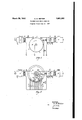
*jects and features, will be better understood represents "one circuit arrangement embody ing the inventionfin Whichja rotatabledis'k or commutator and stationary brushes are provided,-and Fig. 2represents'another embodiment of the invention, in which the disk or commutator is stationary and thebrushes rotatable with respect tolthe. disk or commutator. A
Referring to Fig 1 of'thedrawings,there V is shown a microphone S in series relationship with a batteryG so that speech Varia-- 'tions may be translated into corresponding electrical variationsf These electrical varia-' tions are then impressed upon an amplifier Afo f any'well-known type, preferably of-a vacuum tube type, amplifier amplifying the electrical variations corresponding to the speech impinging upon the microphones. The amplifier currents are then transmitted through I a transformer T to' a brush B which is connected to ground through a resistance R andithesecondary winding of transformer T The .brushlB is associated.
with a commutator or rotatable disk ,K hav- 7 mg a plurality of. segmentseach of which acts; like a; condenser in its capacity to ground. Some of these condensers are designated by the reference character C. Two other brushes, B and B are similarly associated with the commutator K. As the com- .mutator K revolves about its axis its segcorresponding variations in the current flowing between'the plate and filament of that .of the segments of thelcommutator is conbrush B which receives the charge and transmits it to an output circuit, as will be described more fully hereinafter. 'The third brush B short-circuits each of the condens ers through a resistance R as each condenser passes brush B .The electricalcharges. which are surrendered to the brush; 13 as a result of the rotation of the commutator K cause variations in the potential impressed across a resistance R Accordingly, corresponding potential variations are effected between the grid and filament of a three-electrode vacuum tube V, which may be employed in this invention to act as an amplifier. The resistance This in series with a battery G between the grid and filament of vacuum tube V, and these ele- I ments provide the bias necessary for the proper operation of vacuum tube V as an A amplifier. The filament of the vacuum tube V is heated to an electron emitting tempera- 'ture by the flow-of current from a battery C The potential variations between the grid and filament of the vacuum tube V produce vacuum tube, the circuit interconnecting the plate and filament including the primary winding of a transformer T and a battery These amplified current variations are then transmitted through the transformer T "toan electrical wave filter F which may be of any well-known type, preferably of the type described in the patent to G. A. Campbell, No. 1,227,113, dated May 22, 191?. The electrical wave filter F preferably freely transmits currents of frequencies below a :definite limit, while substantially suppressing currents of frequencies above that definite limit. Currents of frequencies above the :definite limit may be considered distortions,
such as harmonics of the signaling currents,
and. are clearly undesirable. The output of the electrical wave filter F is then transmitted to an output circuit O,,which may terminate at a distant point,
F ig. 2 shows another embodiment of the inventlon. 1n which the commutator K is malnt'amed' 1n.a stat onary posit on. Each nected to a separate condenser C. These condensers are preferably of the same capacity and have one terminal in common. Sliprings SR SR and SR rotate about a neednot be repeated.
The operationof the apparatus of F ig. 2 will now be briefly described, it being understood that the general principles of the operation may be applied equally well to the apparatus of Fig. 1. The output of the amp1ifier A is transmitted through transformer T and through a resistance R slip-ring SR and brush-holder Hi to brush B Since brush-holder H is pinned or otherwise permanently. fastened to the slip-ring SR brush B, will rotate about the common axis at the same speed and progressively make contact with the various condensers C. The entire potential transmitted by the amplifier A through transformer T is not impressed uponeach condenser C because of the presence of the resistance R Resistance R decreases each voltage by a definite amount, though these decreased Voltages correspond in every respect to the voltages transmitted by the amplifier A. Condensers Cretain the charges impressed upon them by brush B until brush B makes contact with them. Brush B; is held by brush holder H which is pinned or otherwise fastened to slip-ring SR Brush B rotates at the same speed as brush B and about the same axis though having an angular. displacement with respect to brush B the angular displacement determining the time delay to be effected by the apparatus, Brush B picks up the charges of the various condensers in the same progression in which they were charged and impresses corresponding voltages across the terminals of the resistance R and'between the grid and filament of the vacuum tube V. Brush B follows brush B brush B being held by brush-holder H which is similarly pinned or otherwise fastened to the slip-ring SR Brush B short-circuits each each condenser in' proper condition to receive an electrical charge and thereafter to surrender it. It will be obvious that the resistance R is of a suitable magnitude to thereby prevent the circuits associated with the vacuum tube V from sustaining oscillations If each condenser were short-circuited without series resistance the tendency for the produccondenser through the resistance R thereby placing ,lybelverygreat. V
In orderto showhowthedelay deviceof tion ot-sustained oscillations would obvious- 1 this invention may' .be constructed, assume,
, for illustration, a commutator two feet in di- 1 ameter having Qcommutator segments.v about vone-sixteenth of an inch in width,:separ ated .by very small distances. v Such a commutator would, accordingly, have approximately 1,2 ,segments in its circumference. If it be assumed that the commutator is stationary l and that the brushes. rotate ten revolutions per second,-i. e.,'6 )0 revolutions per. minute, then each brush would in effect pass 12,000
condensers in asecond, In fact, each condenser would be passed'by-each brush tentimes per second; With such a commutator andwithsucha brush speed, it will be apj-isfactorytransmission could be conveniently attained .overa band of 4!,000'01 5,000'cycles.
.Thehigher frequencies which become distort- 7 ed and still other frequencies introduced' by ,therotation of thebrushes about the commuta'tator could be, easilyremoved by anelec- .trical wave filter, particularly a ,low pass filter; which'mav be connected as shown in the draw ngs. If, in a particular arrangement, aset of brushesrotates about a commutator ten times per second, it is obvious that -.,li] 1S possible to attain a-maX mum delay 1n transmission of one-tenth'of a second. If the v ,arrangement made fifteen IeVOllltlODS. per .second the maxlmum delay attainable would I ,beonafifteenth of a second, etc. ,Ifit-becomes desirable to obtain :delays which are greaterthan the max1mum,'then two or more of these arrangements m ght be connected 111 l tandem, or, on the other hand, a greater num- 1 vber. ofsegments-might be provided on each rother characteristic of the electrical circuit commutator, as by making thesesegments narrower or by increasing thediameter of the commutator. Obviously, by, changing" the brush speedgthe maximum delay attainable may be correspondingly changed within practicallimits. Ingeneral, the interval of time delay is decreased as the brush speed is increased, and vice versa.
Each voltage transmitted by the amplifier A to each of the condensers passes through the resistance R If it be assumedthat there exist the ideal conditions'of no leakage and no inductance, then the voltage impressed across each condenser will be i in which E is the voltage output of the amplifier A, B is the magnitude of the resistance in series with the secondary winding of the transformer T C is the capacity of each con- 6 01 E, then denser and}? is the. time during which brush v,B makes contact with each condenser. In I the example given heretofore, for illustrative purposes, the time t would, at a maximum, beone twelve-thousandth of a second] The impressionlof; such a voltage acrosseach condenser bringsabout its charge at annu- ,--evenra-te, the rate of charge being-very great at first and much slower-thereafter. Yet between definite limitsthechargeon each con denser is almost directly proportional to the voltage impressed;there'on.- It vis necessary 7 tooperate between theselimitsto prevent If it be assumed that amplitude tortion.
asfollowsf I V f Y C (microf arads) values of its constants. As has alreadybeen' j The values of'R and C may'thenbe tabulated 1 The values of R and C'may with particular regard to the typeof. stru'ctureemployed and the -u-convenient4-and practical I stated,1,-a-fter each condenser-becomes charged through.- contact with brush B the-voltage across each condenseris then impressed upon thegrid circuitofthe-va'cuum tube-Vthrough contact with brushB Thus, the grid circuit of vacuum tube V will receive a fixed percentage of theoutput of amplifier A, thereby minimizing, the possiblityof amplitude dis- ,tortionp f a L Byvsuitably choosing convenient values for i the constants of the typeof structure employed, the timedelay may be made'substam.
tially independent of frequency, amp'litu'de V Zwitliinwpracticalglimits. The principles underlying this invention may, for "example,
heap-plied to a radio secrecy system in which aband of frequencies cor-responding to voice frequency signals issub-div'ided into a plurality of sub-bands, the; sub-bands being interchanged in the frequency spectrumfto tion for similar time intervals. 1
' g The particular values. stated hereinabove are given merely for illustrative purposes and v .;in practiceother values may be chosen within '{tl'lfi scope of the invention; Y I
been pointed out n '1 While this invention has ,in certain particular arrangementsmerely for In such "the purpose of'illustration, a isto be dis tinctly understood that the general principles of thisinvention may be applied to other'and widely varied organizations Without departing from the spirit of the invention or the scope of the appended claims.
' What is claimed is: r
The method of delaying the transmission of electrical waves representing speech, which comprises progressively converting the electrical waves of varying amplitude into a plurality of electrical charges which vary as do the amplitude variations of said Waves, maintaining each of these electrical charges undisturbed for a predetermined period of time after the beginning of said conversion,
and progressively reconverting the electrical after.
3-, In a system including a plurality of similar surfaces all adjacent to one'another and oppositeto another larger surface, the meth- =od of delaying the transmission of signaling currents of varying amplitudes representing speech, which consists in progressively "charging said similar surfaces to potentials with respect to said larger surface corresponding to the contlnuous variations in amplitude of the signaling currents, retaining the charges on said surfaces a predetermined interval of time and in the same relative mag; nitudes, and discharging all of said surfaces in' the same progression to'reproduce the signaling'currents having the proper amplitude variations. 1
i. Ina delay system, a plurality of similar electrical: condensers, a source of signaling current of varying amplitude representing speech, a first moving element Which" progressively chargessaid electrical condensers inaccordance with the variations in amplitude of the signaling current, an output circuit, a; second moving element whichdisch arges said electrical condensers in the same progression and successively impresses these charges on the output circuit, and'a third moving element which progressively shortcircuits said condensers after they have been discharged and after'their charges have been impressed on the output circuit. 7 i
5. In a delay system, the combination of a plurality of similar electrical condensers, a source of signaling current of varying amplitude representing voice frequency signals, an
output circuit; and three moving elements, one of which progressively charges said electrical condensers in accordance with the amplitude variations of the signaling current,
another of which progressively discharges said electrical condensers and impresses these electrical charges on the output circuit, and the last of which thereafter short-circuits said electrical condensers.
6. The method of delaying the transmission of electrical waves of varying voltages representingvoice frequency signals With apparatus including a plurality of similar electrical condensers, which consists in progresi siv'ely' charging all of said electrical-condensers corresponding to the voltage variations of the electrical waves, and reconverting said electrical charges into the corresp'onding elec- L-iical waves ofvarying voltage a predeter-.
mined interval of time after the beginning of said transmission.
'7; A transmission delay system comprising a commutator having a plurality of segments, a plurality of condensers, one condenser be-.
in g connected to each segment, means for"pr0- gressivel'y charging all of said condensers in accordance with the-variations of speech signaling waves, and means for reconvertingthe charges of all of said condensers in the same progression into the correspondingvariations of speech signaling waves a predetermined interval of time after said charges have been impressed upon said'condensersi 8'. A wave transmission system comprising, a plurality of condensers, three brushes which rotate at the same speed about a common axis and which are separated from each other by predetermined distances alonga circumference'of said axis, a source of speech signals,
means associated with one of said brushes for progressively chargingsaid'condensers in accordance with said signals, means associated with another of said brushes for progressive- "ly' discharging said-condensers in-ordert'o reproduce said signals, and means associated with the third of said brushes for progressively short-circuitingsaid condensers.
In testimony whereof, I have signed my name to this specification this 6th day of. February, 1928. is
CHARLES FETTER.
Priority Applications (1)
| Application Number | Priority Date | Filing Date | Title |
|---|---|---|---|
| US252831A US1851092A (en) | 1927-06-21 | 1928-02-08 | Transmission delay circuits |
Applications Claiming Priority (2)
| Application Number | Priority Date | Filing Date | Title |
|---|---|---|---|
| US200420A US1851090A (en) | 1927-06-21 | 1927-06-21 | Transmission delay circuits |
| US252831A US1851092A (en) | 1927-06-21 | 1928-02-08 | Transmission delay circuits |
Publications (1)
| Publication Number | Publication Date |
|---|---|
| US1851092A true US1851092A (en) | 1932-03-29 |
Family
ID=26895745
Family Applications (1)
| Application Number | Title | Priority Date | Filing Date |
|---|---|---|---|
| US252831A Expired - Lifetime US1851092A (en) | 1927-06-21 | 1928-02-08 | Transmission delay circuits |
Country Status (1)
| Country | Link |
|---|---|
| US (1) | US1851092A (en) |
Cited By (9)
| Publication number | Priority date | Publication date | Assignee | Title |
|---|---|---|---|---|
| US2485567A (en) * | 1946-02-20 | 1949-10-25 | Standard Telephones Cables Ltd | Multiple frequency filter |
| US2509208A (en) * | 1945-07-16 | 1950-05-30 | Standard Telephones Cables Ltd | Direction finder system |
| US2535040A (en) * | 1946-02-20 | 1950-12-26 | Standard Telephones Cables Ltd | Synchronous filter |
| US2771545A (en) * | 1951-11-03 | 1956-11-20 | Collins Radio Co | Multiple frequency communication system |
| US2951990A (en) * | 1956-10-10 | 1960-09-06 | Sun Oil Co | Frequency selective circuits |
| US2966641A (en) * | 1958-03-03 | 1960-12-27 | Reeves Instrument Corp | Variable time delay apparatus |
| US2998942A (en) * | 1953-01-27 | 1961-09-05 | John H Kuck | Autocorrelation discriminator |
| US3096501A (en) * | 1958-01-03 | 1963-07-02 | Thompson Ramo Wooldridge Inc | Signal processing apparatus |
| US3192402A (en) * | 1961-03-09 | 1965-06-29 | Bell Telephone Labor Inc | Delay network |
-
1928
- 1928-02-08 US US252831A patent/US1851092A/en not_active Expired - Lifetime
Cited By (9)
| Publication number | Priority date | Publication date | Assignee | Title |
|---|---|---|---|---|
| US2509208A (en) * | 1945-07-16 | 1950-05-30 | Standard Telephones Cables Ltd | Direction finder system |
| US2485567A (en) * | 1946-02-20 | 1949-10-25 | Standard Telephones Cables Ltd | Multiple frequency filter |
| US2535040A (en) * | 1946-02-20 | 1950-12-26 | Standard Telephones Cables Ltd | Synchronous filter |
| US2771545A (en) * | 1951-11-03 | 1956-11-20 | Collins Radio Co | Multiple frequency communication system |
| US2998942A (en) * | 1953-01-27 | 1961-09-05 | John H Kuck | Autocorrelation discriminator |
| US2951990A (en) * | 1956-10-10 | 1960-09-06 | Sun Oil Co | Frequency selective circuits |
| US3096501A (en) * | 1958-01-03 | 1963-07-02 | Thompson Ramo Wooldridge Inc | Signal processing apparatus |
| US2966641A (en) * | 1958-03-03 | 1960-12-27 | Reeves Instrument Corp | Variable time delay apparatus |
| US3192402A (en) * | 1961-03-09 | 1965-06-29 | Bell Telephone Labor Inc | Delay network |
Similar Documents
| Publication | Publication Date | Title |
|---|---|---|
| US2199634A (en) | Secret communication system | |
| US2098956A (en) | Signaling system | |
| US1851092A (en) | Transmission delay circuits | |
| US2751555A (en) | Extended-range phase comparator | |
| Bennett | Time division multiplex systems | |
| US1671143A (en) | Wave translator | |
| US4078157A (en) | Method and apparatus for regenerating a modified duobinary signal | |
| US2021743A (en) | Multiplex signaling | |
| US2579071A (en) | Time division multiplex system | |
| US2326584A (en) | Multiplex telephony system | |
| US2724742A (en) | Suppressed-carrier amplitude modulation | |
| US1851090A (en) | Transmission delay circuits | |
| US1778085A (en) | Distortionless amplifying system | |
| USRE23579E (en) | Communication system employing | |
| US1911850A (en) | Signaling system | |
| US2339466A (en) | Push-pull amplifier | |
| US1514753A (en) | Signal-receiving system | |
| US2337196A (en) | Signal and noise control system | |
| US2056284A (en) | Signaling method and apparatus | |
| US1796254A (en) | Electrical transformer | |
| US2701276A (en) | Twinplex telegraph signal receiver | |
| US1811941A (en) | Apparatus for reducing disturbing currents | |
| US2294956A (en) | Receiving system | |
| US1704806A (en) | Signaling system | |
| US1995181A (en) | Multiplex receiving apparatus |