US1851081A - Vending machine - Google Patents
Vending machine Download PDFInfo
- Publication number
- US1851081A US1851081A US436982A US43698230A US1851081A US 1851081 A US1851081 A US 1851081A US 436982 A US436982 A US 436982A US 43698230 A US43698230 A US 43698230A US 1851081 A US1851081 A US 1851081A
- Authority
- US
- United States
- Prior art keywords
- coin
- chute
- plate
- head
- dog
- Prior art date
- Legal status (The legal status is an assumption and is not a legal conclusion. Google has not performed a legal analysis and makes no representation as to the accuracy of the status listed.)
- Expired - Lifetime
Links
Images

Classifications
-
- G—PHYSICS
- G07—CHECKING-DEVICES
- G07F—COIN-FREED OR LIKE APPARATUS
- G07F11/00—Coin-freed apparatus for dispensing, or the like, discrete articles
- G07F11/02—Coin-freed apparatus for dispensing, or the like, discrete articles from non-movable magazines
- G07F11/04—Coin-freed apparatus for dispensing, or the like, discrete articles from non-movable magazines in which magazines the articles are stored one vertically above the other
- G07F11/16—Delivery means
- G07F11/24—Rotary or oscillatory members
Definitions
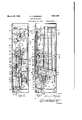
- Figure 1 is a side elevation of the interior mechanism of a machine illustrative of an embodiment of the invention, with the exterior casing in section substantially upon the line 1-1 of Fig. 9;
- Fig. 2 is an elevation. of the mechanism taken at right angles to that of Fig. 1 and showing the casing in section substantially upon the line 2-2 of Fig. 9;
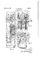
- Fig. 3 is a view similar to that of Fig. 2, showing the mechanism in elevation at the end of the casing opposite that shown in Fig. 2 and with the casing in section substantially upon the line 3-3 of Fig. 9;
- Fig. 4 is an enlarged vertical detail secti on substantially upon the line 44 of Fig. 5 is a sectional view substantially upon the line 5-5 of Fig. 4 with portions broken away and in section;
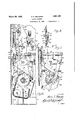
- Fi 6 is an enlarged sectional detail substantlally upon the line 66 of Figs. 2 and 4, with parts broken away and 'in section;
- Fig. 7 is an enlarged sectional detail similar to that of Fi 6 and substantially upon the line 77 of ig. 2, showing coin detecting mechanism
- Fig. 8 is an enlarged sectional detail of m slug ejecting mechanism
- Fig. 9 is a enlarged horizontal section substantially upon the line'9-9 of Fig. 1;
- Fig. 10 is an enlarged horizontal section substantially upon the line 1010 of Fig. 1 05 witih a corner of the casing broken away;
- FIG. 11 is an enlarged sectional detail uf the lower end portion of one of the maga zines and feed blocks there below.
- This machine comprises any suitable form of casing 1 for enclosing the vendin mechanism and provided with a detacha le' back 2 upon which said mechanism is mounted for removal therewith from the casing, said back being also arranged to support, preferably, four small rectangular chutes or magazines 3 for the holding of merchandise to be sold, said merchandise being in the form of small rectangularpackages in superposed relation within said chutes.
- a continuation of one side wall of each chute or magazine is in the form of a spring plate 7 extending downwardly and curved to conform to the curvature of the cylindrical surface of the adjacent block and frictionally engages the same to prevent a too free turning movement of the block and to form a guide or shield to hold within said recess in the block,
- Figs. 1 and 9 there are four parallel magazines 3 and the feed blocks 5 beneath these several magazines are each secured upon a shaft 10 with these shafts in parallelism and extending in the direction of the long cross-sectional dimension of each magazine or toward the front and back of the easing with their ends journaled in side bearing plates which form the sides of the lnchned delivery chute 8, and secured upon each shaft 10 is a gear 11 adjacent one end of each block, these gears being in mesh with each other so that all of the blocks will be turned simultaneously an equal distance.
- the four blocks are secured to their shafts 10 in such relative positions that when the recess 6 in one block is at the upper side 1n position to receive a package, the recess in the next block is at one side, the recess in the next block of the series is at the bottom or in discharge position and recess in the last block is at the other side. Therefore at each quarter rotation of the several blocks, a packa e is discharged.
- This arrangement may, owever, be modified according to the number of chutes employed and in that case the blocks would not be turned exactly one quarter at each actuation, but would be arranged and turned to deliver a single package.
- a plate 12 is mounted on the back wall 2 of the casing for vertical movement thereon, by means of a stud or screw 13 passing through a vertical slot 14 in the plate, and located at one side of said plate is a horizontally extending shaft 15 secured at its rear end in the rear casing wall 2 and at its forward end in the rear wall 16 of the chute 8 between which rear wall and forward wall 17 of said chute, the shafts 10 and blocks are rotatively supported, there being sleeved upon said shaft 15 a power transmitting sleeve 18 to the rear end of which sleeve adjacent the plate 12, is secured a rachet Wheel 19 to turn said sleeve.
- said sleeve being provided at its forward end with a gear 20 which is in mesh with an idler gear 21, which idler in turn is in mesh with one of the gears 11 of the train.
- a pawl 25 having a tail member 26 to which a coiled spring. 27 is attached to normally exert a turning force on the pawl and hold the same against the periphery of the ratchet 19.
- a stop pin 28 on the back wall of the casing is positioned so that the engaging end of the pawl will be caught between said pin and the wheel when the plate 12 is at the upper end of its stroke and the pawl is in a horizontal position and lying within one of the notches of the ratchet wheel.
- the ratchet wheel is thus locked against turning and the plate is limited in its up movement not only b the length of the slot 24 but also by the Stll 23.
- the arm 22 and pawl 25 will be swung about the axis of the shaft 15 to engage said pawl with the next notch of the ratchet wheel, there being four of these notches corresponding in number to the number of blocks 5, and thus upon upward movement of the plate 12, the ratchet wheel w1ll be turned exactly one quarter of a revolution by the engagement of the pawl therewith and turn the several blocks a like distance by the transmission of such turning movement to the train of gears 11 through the sleeve 18, gear 20, and idler 21, causing the delivery of a single package 4 by some one of the blocks from some one of the four chutes 3 at each quarter turn of the ratchet.
- a greater or lesser number of chutes may be employed and the construction modified accordingly to deliver at each actuation, a single package from some one of the chutes.
- a power shaft 29 1s mounted at its rear end in a bearing in the rear wall 2 of the casing-and extends forwardly in parallelism with the shaft 15 through a vertical slot 30 in the lower endportion of said plate 12, and to turn this shaft 23 manually, a hand button 31 is mounted within an opening in the front wall of the casing within a depression or recess in said wall, said button having a slip joint connection 32 with the forward end of said shaft 29, which forward end of said shaft projects through a bearing on a frame plate 33 connected to and rigidly supported from the rear casing plate 2.
- a sleeve 34 having keyed thereto, a cam member '35 provided with a laterally pro ecting cam portion to engage a pair of pins or studs 36 and 37 on the lower end .portlon of the plate 12.
- These two studs are located on said plate, one at each side of the vertical guide slot 30 in the plate, and-normally, the plate is held in raised position by the engagement of the cam 35 beneath the stud 36.
- the upper end of said plate is provided with a laterally extending lug 38a to engage a stop member 39 which is pivotally su ported at 40-to be swung into and out of the path of the lug 38a by means of a crank arm 41 and a bar 42 pivotally attached to the free end of said crank.
- the lower end of this bar 42 is pivotally connected to the free end of a swinging arm.
- a coin stop arm 46 having a laterally bent end 47 adapted to be projected through a side opening'in the chute across the path of a coin passing down said chute when said arm 46 is released from the shoulder 45 and said arm is turned upon its pivot 48 by means .of a spring 49 tending to swing the upper end of said arm toward the chute and holding it against said shoulder when the parts are in normal position.
- a semicircular flange 46a (Fig. 4) is secured to one side of a circular head on the sleeve 34 to en gage the lower end of said arm 46 when the sleeve and head are rotated as hereinafter described.
- means for testing the member inserted, said means comprising a plunger 54 mounted in bearings for free endwise movement and provided with a sharpened end 55 adapted to be projected through a side opening in the chute 44 into engagement with coin, and this excess movement will be suf-' ficient to eifect a locking of the delivery mechanism through the operation of means hereinafter described.
- this mechanism including a weight block 56 placed in one of said chutes upon the stack of packages 4 therein to move downward as the packages are delivered from the bottom of the stack. Said block is'formed with a transverse bore in which is a spring pressed.
- the wei ht 56 When the magazines are re-filled, the wei ht 56 must be raised in order to place the pacEages in that magazine and this raising of said weight permits the lever 59 to be swung to normal position by its spring, but the bar 72 being still in down position with the dog 71 below the projection 63a on the arm 63, the deflector blade 65 is still across the coin chute 44.
- the operator will manually release the operating mechanism which has been locked as hereinafter described, and by then turning the handle 31, will eflect an upward movement of the bar 72 which will bring the do 71 into engagement with the lower curve side of the projection 63a and swing the lever 63 back to normal position where it will be held by the engagement of the dog 61 therewith.
- This com deflecting mechanism is thus re-set and held in position to again operate upon the emptying of the magazines.
- Such coin deflecting mechanism is necessary for one of said magazines only as packages are delivered from the several magazines in a certain sequence, and as the magazine provided with such mechanism is the shorter one of the series so that it will always be the first to become empty.
- a plate 73 (Figs. 1, 2 and 4) is attached to the lower end of said bar, said plate being formed with a longitudinal slot through which the shaft 29 projects and on said shaft adjacent said plate is secured a cam 74 to engage pins 75 on said plate and raise or lower said plate and bar 2 by the turning of said shaft.
- the bar 72 is therefore always moved by rotation of the operating handle, said bar being always urged in an upward direction by means of a coiled spring 76 attached thereto. (See Fig. 2.)
- the operating or power shaft 29 has a handle or button 31 connected thereto for turning said shaft, and it is this turning motion of said shaft which, by suitable mechanism hereinafter described is transmitted to the sleeve 34 (Fig. 4) on this shaft, to which sleeve-the cam 35 is secured for moving the plate 12 vertically and through the pawl and ratchet (25 and 19) rotating the-delivery or feed blocks 5 to deliver
- a circular head 78 is secured to or formed'integral with the shaft 29 adjacent the end of said sleeve and pivotally attached 'to one side of said head asat -79,""(Figs.
- the plunger 54 is reciprocated toward and from a coin held suspended in the chute 44 by the stop member 46, in proper timed relation to the movement of the other parts, by means of a lever 82 pivotally connected at its upper end to said plunger and itself pivotally supported intermediate its ends at 83 and provided on its lower end with a laterally projecting lug 84 to engage a groove 85 (Figs. 457) in the side face of a circular head 86 formed integral or secured to the sleeve 34 with a space between said head and the head 7 8 within which space the lower end of said lever is adapted to swing and carry said lug from said inner.
- a tail projection 90 on said dog 80 comes into contact with the pin 88 on said lever 82 and said dog is thrown out of engagement with said lug 81, thus disconnecting said operating shaft 29 from said sleeve 34, permitting said sleeve in that to be at once rotated 'in a reverse direction by a coiled spring 91 made fast at one end within a 'perlpheral groove in a second cir-, cular head or disk 92 integral with said sleeve 34 and spaced from the adjacent side of the head 86, said spring being suitably anchored at its opposite end after passing partially around said head, so that said springwill be ut under tension'when said sleeve 1S turne in one direction by the engagement of said dog 80 therewith and when the handle 31 is turned to the right.
- a coiled spring 93 is secured at one end within a peripheral groove in the head 7 8 to be wound thereon by the turning
- the throw or degree of turning movement of the head 86 in each direction is limited by the len h of the groove 85 when the throw of the roc er 82 is so limited by a good coin that its stud 84 is confined within the inner groove 85, but should a very thin coin or slug be inserted, or a slug with a central opening, then the plunger 54 will be permitted by the slug to move endwise suflicientl to swing said'rocker far enough so that said stud will pass into the peripheral groove 87 and the degree of turning movement of the head will then be limited by the'length of said peripheral groove which isv considerabl than the inner groove, and the ead and sleeve will be prevented from turning far enough to bring the cam 35 (Fig. 6) into position to raise the plate 12 and operate the delivery mechanism.
- the opposite end of said dog 96 is adapted to engage a tooth or projectmn 97 on the head 78 when said head has reached the limit of its forward or right hand turning movement and has reached such a osition that the tail 90 of the dog 80 is just rought into engagement with the pin 88 to disconnect the sleeve and shaft at the end of the delivery stroke.
- a latch mem er or dog- 98 is pivotally supported adjacent the pivot for said dog, said latch having a lateral projection at its upper end to engage over a lug .99 on said dog, said latch and dog being urged toward each other by. a; coiled spring connecting the same, and thus the dog is latched down in position to engage said ratchet teeth, after a certain degree of turning movement of the head, to revent backward turning of the head by the spring 93.
- a coin chute Leading from the coin slot 77 is a coin chute, the end of which adjacent theslot, is formed by a plate 102 and the lower open end of this portion ofthe chute, opens into a rearwardly and downwardly inclined connecting chute portion 103, one side of which is formed by a flat plate 104 which also forms together with the plate 102, the entrance end of the chute, said inclined chute portion 103 extending rearwardly and downwardly with its rear end open opposite the up er end of the vertical chute portion 44 so t at a coin inserted through the slot 77 will drop down into the upper end of inclined chute'portion 103, and if it be a good coin, will pass therethrough and out at the lower end into the upper end of chute-44?; I, v
- the side of said chute ortion 103 opposite the-plate 104 is formed by a pivotallfi supported plate 105, said plate being pivota y attached at its upper end to the plate 104 by means of laterally extending ears 106 projecting from the upper edge of said plate so that the lower edge of said plate will be held by gravity against the adjacent face of the plate 104 with said. plate in a downwardly inclined position and spaced from, the late 104 except at its lower edge, thus forming; a somewhat V-sha'ped chute or passage 103 for 'coins between these plates.
- An elongated opening 107 is provided in the plate 105 which opening is of such a width that a slug rolling down this passage and of less diameter than that of the good coin, will not s an this opening and will therefore tilt latera 1y, due to the inclination of the plate 105 and to a longitudinal rib 108 struck up from plate 104 opposite said openings, and will fall out through said opening.
- a coin or slug of less than regulation diameter will therefore be discharged from the chute and will not serve'to operate the machine.
- flap or stop member 110 pivoted to the plate 105 at its upper end near the upper edge of said plate to swing freely longitudinally of the chute or passage against the inner face of said plate in the path of the slug which will be stopped thereby and held until released through the bottom of the passage by the swinging of the plate 105 away from plate 104 as hereinafter set forth.
- a coin of proper weight will however, have inertia enough when it comes in contact with said swinging stop, to swing the same out of the way and pass on down the chute.
- a bar 111 is secured at its lower end to the operating bar 72 to move therewith, it being secured to and spaced from said operating bar by spacers 111a and is guided at its upper end in any suitable manner for free longitudinal movement against the face of the plate 104 opposite that opposed by the plate 105 and across the opening in plate 104 through which the ears 106 project.
- This bar 111 being connected to the bar 72 will be moved downwardly whenever said bar 72 is moved by its cam 74, as previously described.
- the plate 105 is swung on its pivotal support away from plate 104 to open the chute 103 at its lower side and permit any slug or coin therein to drop out, by providing a stud 112 on said plate 105 arranged to pro ect through the opening in plate 104 into the path of a lug 113 on bar 111 to engage said stud and thus swing said plate 105 upon each down movement-of the bar whenever the handle 31 m is turned, and to further guard against an iron or similar slug of the exact size of a good coin from passing on down the chute 44 and causing the machine to operate and deliver merchandise, a magnet 114 is secured to the 1:? plate 104 with its poles projecting through an opening in said plate to attract and hold the slug.
- a sweep 115 is pivotally supported by the 26 plate 104 above the upper open side of said chute 103 to be swungacross the poles of the magnet within said chute when the plate 105 is swung by the downward movement of bar 111, said sweep being pivotally connected at 116 to the upper end of said bar.
- a slug chute 117 is provided directly below the lower side of chute 103, and this chute or conduit 117 has a laterally extended lower portion 118 with its lower open end above the upper end of the merchandise chute 8 (Fig.9) so that these slugs will be discharged into the delivery cup 9 without operating the machine.
- a slug or coin of light weight is therefore stopped by the flap 110. and one which is formed of a metal to be. attracted by the magnet is also stopped, while a thin slug will pass out through the slot 109, or one which is under size will be discharged laterally through the opening 1.07. There. is, therefore, small likelihood of any spurious coin or'substitute getting into the chute 44, but should it do so it is again subjected to a further test by the plunger 54 which will operate to lock the delivery mechanism should the inserted piece be too thin, be of soft metal or have a center hole therein, all as previously set forth.
- the swinging deflector blade 65 is provided to be operated by the weight block 56 resting upon the merchandise in one of the magazines to move .i downwardly therein as the packages 4 are dis charged. A construction is thus provided which guards against every possibility of operating the delivery mechanism without inserting a good coin.
- a pendulous bar 119 is pivoted at 120 adjacent one ed e of the chute 44 opposite the end of the plunger 54, and is provided with an arm 121 extending laterally therefrom through an opening in the edge of the chute to be engaged by a coin passing down the chute past the plunger, so that the weight of the coin falling upon the end of said arm will swing said bar against the action of a weight 122 at one side of the bar tending to swing the bar and project its arm into the path of the coin in the chute.
- the lower or free end of the bar 119 is adaptedto swing transversely of the circular head 86 (see Fig. 5) which is provided with a shoulder 123 on the periphery thereof to engage the lower end of said bar and limit the turning movement of the head when no coin is inserted or is dropped down in the chute to engage said arm and swing said bar out of the path of said shoulder.
- a bracket or fixed arm 124 is secured to the casing and is formed with a slot 125 to receive the lower end of said bar, the arm beina free to swing out of said slot and out of the path of said shoulder when operated by a coin passing down the chute.
- the head 86 is therefore limited in its turning unless a coin be inserted to swing the bar, and injury to the mechanism is prevented thereby when a person tries to forcibly rotate the handle.
- the present machine is essentially a vending machine and therefore necessarily includes coin control means for controlling its operation of vending.
- a specific construction, combination and arrangement of vending apparatus is provided, so that the specific construction and arrangement of control mechanism may be combined therewith, the whole presenting a compact, and simplified construction of complete vending machine wherein the delivery of merchandise is dependentupon the insertion of a coin of proper value.
- a vending machine the combination of an upwardly extending magazine, merchandise delivery mechanism in said magazine for feeding packages of merchandise,- one at a time, from the magazine, a pawl and ratchet for transmitting intermittent rotation to said delivery mechanism, a reciprocable member for operatin said pawl, coin operated stop means for limiting the reciprocation of said member, a manually operated power member, a rotary member provided with means for efiecting reciprocation of said reciprocable member, and means for operatively connecting and disconnecting said power member and rotary member.
- a hand operated power travel into which it is thrown by shaft, and means for transmitting movement from said-shaft to said rotary feed members including a pawl and ratchet, a reciprocable member for operating said pawl, means for eflecting reciprocation of said reciprocable member by rotation of said shaft, a head free to rotate on said shaft and a head secured to said shaft with said heads arran ed in opposed relation, a connecting mem er for detachably connecting said heads to turn together, and a coin controlled member for operating said connecting member.
- the combination of merchandise elivery mechanism including rotatable feed members, a manually operated rotatable operating member, means for transmitting motion from said operating member to said delivery mechanism including a head loose on said operating member and a head secured to said member, a connecting member for connecting said heads, a member controlled in its operation by the insertion of a coin, a lever connected to said coin controlled member and provided with a projection, one of said heads being formed with connected grooves forming two paths of travel for said projection to control the operation of said connecting member.
- a vending machine the combination of merchandise delivery mechanism, a manually operated rotatable operating member having a head, means including a rotatable read opposed to said head, for transmitting motion from said head on said operating member to operate said delivery mechanism, a stop to limit rotation of said operating member, means for detachably connecting said heads to cause them to turn together, a member controlled in its operation by the insertion of a coin, and a lever for operating said means for connecting said heads and formed with a projection, one of said heads being formed with connected grooves forming two paths of travel for said projection. whereby said lever is controlled by said coin controlled member to efi'ect a disconnection of said heads, depending upon the path of said coin controlled member.
- the combination of merchandise delivery mechanism including rotatable feed members, a manuall rotatable operating member having a ead, yielding means for rotatin said operatin member in a direction-opposite that in whic it is manually rotated, means for transmitting motion from said head to operate said delivery mechanism, a longitudinally movable member controlled in its operation by the engagement thereof with an inserted coin, a lever operated by said coin controlled member and adapted to operate said motion transmitting means, means for preventing retrograde rotation of said head when rotated a predetermined distance manually, means for operating said retrograde preventing means to disconnect said operating member and said motion transmitting means when said operating member approaches the end of its turning movement and permit backward turning of said operating member by said yielding means when said operating member is released by the operator.
- the combination of merchandise delivery mechanism including a rotatable member, a rotatable operating member having a head, a dog carried by said head to engage said rotatable member and transmit motion from said operating member to said delivery mechanism, means controlled in its operation by the insertion of a coin, for operating said dog to disconnect said delivery mechanism from said operating member, and a stop to limit rotation of said operating member, said coin controlled means being brought into engagement with said dog by the turning of said head, to release said dog from engagement with said rotatable member as said head approaches the end of its turning movement.
- a vending machine the combination of merchandise delivery mechanism, a rotatable operating member, means for transmitting motion from said operating member to said delivery mechanism to operate the same and including a dog, a reciprocable coin controlled member,' a swinging member controlled by the movement of said reciprocable member for operating said dog, and means on said swinging member for limiting rotation of said operating member.
- a vending machine the combination of a magazine for holding packages of merchandise in superposed relation, delivery mechanism for taking said packages, one at a time, from the lower end of said magazine, a manually rotated operating member, means for transmitting motion from said operating member to operate said delivery mechanism, said motion transmitting means including coin controlled mechanism, a coin chute, a weight member upon saidpackages in said magazine, lever mechanism to be operated by said weight as the same nears the bottom of said magazine, and a member pivotally supported adjacent said coin chute and having a blade curved concentric with the pivot of said member to swing across said chute, said member being adapted to be swung by said lever mechanism to brin its blade into the path of a coin approac ing said coin controlled mechanism to deflect said coin from said chute and return the same to the operator.
- a vending machine the combination of a magazine for holding merchandise packages in superposed relation, a rotary feed member for feeding packages, one at a time, from the lower end of said magazine, a rotary shaft having a handle for manual operation and provided with a circular head, motion transmitting means including a pawl and ratchet for imparting an intermittent rotation to said rotary feed member and also including a rotatable member having a circular head in opposed relation to said head on said shaft and a longitudinally reciprocable member for operating said pawl, said member being reciprocated by the rotary motion of said rotatable member, a connecting member pivotally attached to one of-said heads to transmit motion to the member having the opposed head, a lever controlled in its movement by the insertion of a coin and swung thereby into the path, of said connecting member to operate the same and disconnect said manually operated shaft from said opposed rotatable member.
- a vending machine the combination of a magazine for holding merchandise in package form, a rotary feedmember beneath said magazine, an operating shaft provided with means for applying manual power for turning the same, said shaft having a circular head, a sleeve on said shaft rotatable thereon independently thereof and provided with a cam member and a circular head in opposed relation to said head on said shaft, said head when said lever is swung to one position, the turning movement of said sleeve and head being limited by the length of said grooves therein engaged by said lug, one of said grooves being of greater length than the other, a vertically reciprocable plate operated by said cam on said sleeve when said sleeve is turned, and a pawl and ratchet operated by the reciprocation of said plate for transmitting intermittent motion to said rotary feed
- a vending machine as characterized in claim 11, and further characterized by being provided with a movable stop member for stopping an inserted coin in position to limit the swinging movement of said lever having said lug to engage said grooves in said head, means for locking said stop member out of operative position, means in the path of the inserted coin for releasing said locking means, and means on the said head on said sleeve for engaging said stop member and restoring the same to inoperative position upon full rotation of said sleeve and head.
- a vending machine the combination of a magazine for holding packages, delivery mechanism including a manually operable rotatable shaft, means for discharging packages from said magazine, one at a time, means for transmitting motion from said shaft to operate said discharge means, coin controlled mechanism for controlling the operation of said motion transmitting means, said coin controlled mechanism including a coin chute, a stop member for stopping a coin passing down said chute, a head on said shaft, means on said head for operating said stop member, a longitudinally reciprocable member to engage and test a coin stopped in said chute by said stop member, and means operatively engaging said head for moving said coin testing member in timed relation to the movement of said stop member.
- said sleeve being formed with concentric K inner and outer grooves in a side face of said head with saul grooves connected at one end a dog plvotally attached to said head'on sai shaft to engage a projection on said sleeve,
- a lever having a lug to engage said grooves in said head of said sleeve, means attached to said lever to engage an inserted coin and regulate the swinging movement of said levdr to determine which of said grooves will be engaged by said lug on said lever, a. pin on said lever to engage and operate said dog
Landscapes
- Physics & Mathematics (AREA)
- General Physics & Mathematics (AREA)
- Vending Machines For Individual Products (AREA)
- Control Of Vending Devices And Auxiliary Devices For Vending Devices (AREA)
Description
March 29, 1932.
H. s. BENJAMIN VENDING MACHINE Fil'ed March 19 1930 4 Sheets-Sheet l JFII INVENTOR ATTORNEY5 March 29, 1932. H. s. BENJAMIN 1,851,081
VENDING MACHINE Filed March 19, 1930 4 Sheets-Sheet 2 I mu w:is??? gm Q INVENTOR ATTORNEYS March 29', 1932. H. s. BENJAMIN VENDING MACHINE Filed March 19', 1930 4 Sheets-Sheet 3 HHH IIIF lNVENTO i? ATTORNE March 29, 1932.
H. s. BENJAMIN VENDING mcm'm:
, 1950' 4 Shets- Shet 4 Filed March 19 Patented Mar. 29, 1932 PATENT OFFICE HARRY S. BENJAMIN, OF UTICA, NEW YQRK VENDING MACHINE Application filed larch 19, 1930. Serial No. 438,982.
10 struction and operation whereby possibility of manipulation .of the machine without the insertion of a good coin is precluded and no delivery of merchandise is insured re ardless of, manipulation or the insertion any instrument of whatever nature, except by the insertion of a good coin of standard size, shape and thickness. It is also an obJect to guard against manipulation of the coin in inserting the same in the machine, as by a partial insertion and withdrawal or by the nsertion of a. good coin with a cord or wire attached thereto whereby said coin may be withdrawn after releasing the delivery mechanism; and further, to provide certain other new and useful features, all as hereinafter more fully set forth.
With the above and other ends in view, the invention consists in the matters hereinafter set forth and more particularly pointed out in the appended claims, reference being had to the accompanying drawings in which Figure 1 is a side elevation of the interior mechanism of a machine illustrative of an embodiment of the invention, with the exterior casing in section substantially upon the line 1-1 of Fig. 9;
Fig. 2 is an elevation. of the mechanism taken at right angles to that of Fig. 1 and showing the casing in section substantially upon the line 2-2 of Fig. 9;
. Fig. 3 is a view similar to that of Fig. 2, showing the mechanism in elevation at the end of the casing opposite that shown in Fig. 2 and with the casing in section substantially upon the line 3-3 of Fig. 9;
Fig. 4 is an enlarged vertical detail secti on substantially upon the line 44 of Fig. 5 is a sectional view substantially upon the line 5-5 of Fig. 4 with portions broken away and in section;
Fig. 7 is an enlarged sectional detail similar to that of Fi 6 and substantially upon the line 77 of ig. 2, showing coin detecting mechanism Fig. 8 is an enlarged sectional detail of m slug ejecting mechanism;
Fig. 9 is a enlarged horizontal section substantially upon the line'9-9 of Fig. 1;
Fig. 10 is an enlarged horizontal section substantially upon the line 1010 of Fig. 1 05 witih a corner of the casing broken away; an
(Fig. 11 is an enlarged sectional detail uf the lower end portion of one of the maga zines and feed blocks there below.
This machine comprises any suitable form of casing 1 for enclosing the vendin mechanism and provided with a detacha le' back 2 upon which said mechanism is mounted for removal therewith from the casing, said back being also arranged to support, preferably, four small rectangular chutes or magazines 3 for the holding of merchandise to be sold, said merchandise being in the form of small rectangularpackages in superposed relation within said chutes.
These small rectangular packages 4 are thus held in vertical columns and permitted to slide freely downward within said chutes or magazines as the packages are removed, one at a time, from the lower end of each column by means of rotatable feed members or blocks 5, one of said feed blocks being located directly beneath each column and each formed with a notch or recess 6 (see Fig. 11) of a shape and size to receive a single package and located in one side of each block.
A continuation of one side wall of each chute or magazine is in the form of a spring plate 7 extending downwardly and curved to conform to the curvature of the cylindrical surface of the adjacent block and frictionally engages the same to prevent a too free turning movement of the block and to form a guide or shield to hold within said recess in the block,
the package removed thereby from the lower end of the column when said block is rotated, said shield endin at the upper end of a single chute 8 for all 0 said magazines, and which chute leads to a delivery cup 9 opening through the front wall of the casing.
In the present constructlon and arrangement as shown in Figs. 1 and 9, there are four parallel magazines 3 and the feed blocks 5 beneath these several magazines are each secured upon a shaft 10 with these shafts in parallelism and extending in the direction of the long cross-sectional dimension of each magazine or toward the front and back of the easing with their ends journaled in side bearing plates which form the sides of the lnchned delivery chute 8, and secured upon each shaft 10 is a gear 11 adjacent one end of each block, these gears being in mesh with each other so that all of the blocks will be turned simultaneously an equal distance.
The four blocks are secured to their shafts 10 in such relative positions that when the recess 6 in one block is at the upper side 1n position to receive a package, the recess in the next block is at one side, the recess in the next block of the series is at the bottom or in discharge position and recess in the last block is at the other side. Therefore at each quarter rotation of the several blocks, a packa e is discharged. This arrangement may, owever, be modified according to the number of chutes employed and in that case the blocks would not be turned exactly one quarter at each actuation, but would be arranged and turned to deliver a single package.
To actuate the train of gears consisting of the several gears 11 and thus simultaneously rotate all of the blocks 5, a plate 12 is mounted on the back wall 2 of the casing for vertical movement thereon, by means of a stud or screw 13 passing through a vertical slot 14 in the plate, and located at one side of said plate is a horizontally extending shaft 15 secured at its rear end in the rear casing wall 2 and at its forward end in the rear wall 16 of the chute 8 between which rear wall and forward wall 17 of said chute, the shafts 10 and blocks are rotatively supported, there being sleeved upon said shaft 15 a power transmitting sleeve 18 to the rear end of which sleeve adjacent the plate 12, is secured a rachet Wheel 19 to turn said sleeve. said sleeve being provided at its forward end with a gear 20 which is in mesh with an idler gear 21, which idler in turn is in mesh with one of the gears 11 of the train.
Free to turn upon the rear end of the shaft 15 or sleeve 18 is an arm 22 adjacent the ratchet wheel 19 and the free end of this arm carries a screw stud 23 which projects through and is free to slide within a horizontal slot 24 in the'plate 12. Pivotally mounted upon this stud 23 is a pawl 25 having a tail member 26 to which a coiled spring. 27 is attached to normally exert a turning force on the pawl and hold the same against the periphery of the ratchet 19. A stop pin 28 on the back wall of the casing is positioned so that the engaging end of the pawl will be caught between said pin and the wheel when the plate 12 is at the upper end of its stroke and the pawl is in a horizontal position and lying within one of the notches of the ratchet wheel. The ratchet wheel is thus locked against turning and the plate is limited in its up movement not only b the length of the slot 24 but also by the Stll 23.
When the plate 12 slides downwardly as will be hereinafter described, the arm 22 and pawl 25 will be swung about the axis of the shaft 15 to engage said pawl with the next notch of the ratchet wheel, there being four of these notches corresponding in number to the number of blocks 5, and thus upon upward movement of the plate 12, the ratchet wheel w1ll be turned exactly one quarter of a revolution by the engagement of the pawl therewith and turn the several blocks a like distance by the transmission of such turning movement to the train of gears 11 through the sleeve 18, gear 20, and idler 21, causing the delivery of a single package 4 by some one of the blocks from some one of the four chutes 3 at each quarter turn of the ratchet. Obviously, a greater or lesser number of chutes may be employed and the construction modified accordingly to deliver at each actuation, a single package from some one of the chutes.
To actuate the slide plate 12, and to guide the lower end of said plate, a power shaft 29 1s mounted at its rear end in a bearing in the rear wall 2 of the casing-and extends forwardly in parallelism with the shaft 15 through a vertical slot 30 in the lower endportion of said plate 12, and to turn this shaft 23 manually, a hand button 31 is mounted within an opening in the front wall of the casing within a depression or recess in said wall, said button having a slip joint connection 32 with the forward end of said shaft 29, which forward end of said shaft projects through a bearing on a frame plate 33 connected to and rigidly supported from the rear casing plate 2.
Sleeved upon the rear end portion of this powershaft 29 to turn thereon independently of said shaft, is a sleeve 34 having keyed thereto, a cam member '35 provided with a laterally pro ecting cam portion to engage a pair of pins or studs 36 and 37 on the lower end .portlon of the plate 12. These two studs are located on said plate, one at each side of the vertical guide slot 30 in the plate, and-normally, the plate is held in raised position by the engagement of the cam 35 beneath the stud 36.
- movement by latch mechanism hereinafter described, and will descend by gravity aided by a light coiled spring 38 attached to the lower end of the plate and to the full extent of movement permitted by the slots 14 and 30, thereby swinging the arm- 22 to engage the pawl 25 with the next notch of the ratchet 19, so that upon further turning of the cam 35 in the same direction, the plate 12 w1ll positively raised by the engagement of said cam with the other stud 37, and thus, through the engagement of. said pawl with the advanced notch of said ratchet, rotate the delive blocks 5 through the necessary angle to discharge a package from some one of the magazines 3. To ositively stop said cam 35 in roper position to hold the plate 12 in raised position while the mechanism is at rest, a sto 35a is provided to be engaged by a lateral ug on the cam.
To control the downward movement of the actuating plate 12 so that if other than a good com be inserted, the plate will be stopped to prevent the delivery of merchandise, the upper end of said plate is provided with a laterally extending lug 38a to engage a stop member 39 which is pivotally su ported at 40-to be swung into and out of the path of the lug 38a by means of a crank arm 41 and a bar 42 pivotally attached to the free end of said crank. The lower end of this bar 42 is pivotally connected to the free end of a swinging arm. 43 pivotally supported at its opposite end upon the lowerend of a coin chute 44 outside of said chute to extend thereacross and is-provided with a notch or shoulder 45 to engage a coin stop arm 46 having a laterally bent end 47 adapted to be projected through a side opening'in the chute across the path of a coin passing down said chute when said arm 46 is released from the shoulder 45 and said arm is turned upon its pivot 48 by means .of a spring 49 tending to swing the upper end of said arm toward the chute and holding it against said shoulder when the parts are in normal position. (See Fig. 6.) To swing said arm 46 against the action of the spring 49 and bring it into latched or normal position with its end 47 held retracted from the coin chute, a semicircular flange 46a (Fig. 4) is secured to one side of a circular head on the sleeve 34 to en gage the lower end of said arm 46 when the sleeve and head are rotated as hereinafter described.
otally supported at one end intermediate the ends of the bar 42 to extend transversely of said bar loosely between a pair of pins 51 projecting laterally from said bar, and the free end of this trip extends through an opening in the side of the chute 44 to swing across the path of a coin passing down said chute. When such coin strikes the free end of this trip plate, said plate will swing downwardly into engagement with the pin 51 therebeneath, with sufficient force to move the bar downwardly against the action of a coiled spring 51a which is of just suflicient strength to-balance the weight of the bar and attached parts, and unlatch the arm 43 from engagement with the coin stop arm 46 which will then be immediately swung by its spring 49, projecting its stop end across the path of the coin coming down the chute, where it will be supported and held by this sto until such time as it is released by thewith rawal of said sto as hereinafter described, and when so re eased, it will pass on down the chute, out the lower end thereof and into an inclined chute 52 extending laterally to a point over a coin receptacle 53 at the bottom of the casing.
When the bar 42 is moved downwardly by the impact of a coin on the trip 50 as described, this downward movement of the bar will swing the stop member 39 out of the path of the lug 38a on the actuating plate 12 so that said plate may move on downwardly, provided it be released and actuated as hereinafter described.
While the coin, slug or washer inserted, is supported by the stop end 47 of-the arm 46, means is provided for testing the member inserted, said means comprising a plunger 54 mounted in bearings for free endwise movement and provided with a sharpened end 55 adapted to be projected through a side opening in the chute 44 into engagement with coin, and this excess movement will be suf-' ficient to eifect a locking of the delivery mechanism through the operation of means hereinafter described.
Should a coin be inserted and the machine fail to deliver a package due to the fact that a particular magazine had become empty,
mechanism is provided whereby that com will be returned to the party inserting it, this mechanism including a weight block 56 placed in one of said chutes upon the stack of packages 4 therein to move downward as the packages are delivered from the bottom of the stack. Said block is'formed with a transverse bore in which is a spring pressed.
pin 57 (Fig. 9) adapted to be projected by said spring, through an opening 58 in one side wall of the magazine or chute 3 (Figs. 2-3) near the lower end thereof so that when the packages are nearly all withdrawn, this pin will be projected through said openits iio
ing into the path of the lower end of a lever 59 pivoted intermediate its ends at 60 ad acent the rear side of said magazine and with its upper end portion extending upwardly from said pivot to a pomt ad acent the under side of a dog 61 pivoted at one end to one side wall of the coin chute 44 with 1ts opposite end provided with a projection 62 to engage the upper end of a lever 63 plvotally supported intermediate its ends at 64 with its lower end formed or provided wlth a laterally extended blade 65 curved concentric w th said pivot to be projected by theswing ng of said lever, into the path of a com passing down said chute and deflect said coin from the chute 44 into the upper end of a chute on its pivot with its lower end in the path of the pin 57, a stop pin 'on said lever'limiting such turning movement by said spring. With the parts in the position shown n Fig. 3, and with a supply of packages still contained 'inthe bottom of the magazine 3, a good coin will pass freely down the coin chute 44 until stopped by the end 47 of stop arm 46, but should these packages have been all or nearly all discharged from said magazine and the weight 56 lowered thereby, bringing the pin 57 into engagement with the lower end of the lever 59, swinging the same suflicientlyv to cause its upper end to engage and release the dog 61, said lever 63 will be swung by its spring 68 toward a dog 71 pivotally attached to an upwardly extending longitudinally reciprocable operating bar 72 and stopped in its swinging movement thereby with its blade or foot 65 still out of the coin chute 44. This leaves said chute free so that upon the insertion of a succeeding coin, said coin may pass down to the stop 47 and there operate to release the vending mechanism to vend another package upon the turning of the handle 31 to effect such release and vendthe package. Such operation of the handle 31 will cause a downward movement of said bar 72 as will be hereinafter described, and this movement of said bar will move said dog 71 out of the path of the laterally extending and curved projection 63a on lever 63 which contacted said dog when said lever was .re j leased by the dog 61, and thus said lever63 will be swung by its spring and its blade 65 will be projected across the coin chute'44 'so that the next coin inserted will be deflected thereby and no. package will be delivered, indicating that the several magazines are the packages 4 into the chute 8.
empty or nearly so. The said deflector remains in this position across the chute until re-set as hereinafter described.
When the magazines are re-filled, the wei ht 56 must be raised in order to place the pacEages in that magazine and this raising of said weight permits the lever 59 to be swung to normal position by its spring, but the bar 72 being still in down position with the dog 71 below the projection 63a on the arm 63, the deflector blade 65 is still across the coin chute 44. However, after having filled the magazines, the operator will manually release the operating mechanism which has been locked as hereinafter described, and by then turning the handle 31, will eflect an upward movement of the bar 72 which will bring the do 71 into engagement with the lower curve side of the projection 63a and swing the lever 63 back to normal position where it will be held by the engagement of the dog 61 therewith. This com deflecting mechanism is thus re-set and held in position to again operate upon the emptying of the magazines.
Such coin deflecting mechanism is necessary for one of said magazines only as packages are delivered from the several magazines in a certain sequence, and as the magazine provided with such mechanism is the shorter one of the series so that it will always be the first to become empty.
To operate the bar 72, a plate 73 (Figs. 1, 2 and 4) is attached to the lower end of said bar, said plate being formed with a longitudinal slot through which the shaft 29 projects and on said shaft adjacent said plate is secured a cam 74 to engage pins 75 on said plate and raise or lower said plate and bar 2 by the turning of said shaft. The bar 72 is therefore always moved by rotation of the operating handle, said bar being always urged in an upward direction by means of a coiled spring 76 attached thereto. (See Fig. 2.)
As previously described, the operating or power shaft 29 has a handle or button 31 connected thereto for turning said shaft, and it is this turning motion of said shaft which, by suitable mechanism hereinafter described is transmitted to the sleeve 34 (Fig. 4) on this shaft, to which sleeve-the cam 35 is secured for moving the plate 12 vertically and through the pawl and ratchet (25 and 19) rotating the-delivery or feed blocks 5 to deliver To transmit motion from the operating or power shaft 29 to the sleeve 34 to turn said sleeve in one direction and thereby operate the delivery mechanism to deliver a package 4 after the insertion of a good coin, a circular head 78 is secured to or formed'integral with the shaft 29 adjacent the end of said sleeve and pivotally attached 'to one side of said head asat -79,""(Figs. 4 and 5) .is a pawl or dog {80 ha inga foot at its inner manner side to engage a radial In 81 on the adjacent end of the sleeve 34, so t at .when the shaft 29 and head 7 8 are turned toward the right, said dog will engage said lug and rotate the sleeve in the same direction. This dog 80 is controlled in its operation by the coin detecting mechanism which includes the plunger 54 so that if a substitute for a good coin be inserted and is stopped inits movement down the coin chute 44 by the sto member 48, suchsubstitute will be disclosed y the movement of said plunger and said dog will be prevented from turning the sleeve to efiect a delivery of merchandise.
The plunger 54 is reciprocated toward and from a coin held suspended in the chute 44 by the stop member 46, in proper timed relation to the movement of the other parts, by means of a lever 82 pivotally connected at its upper end to said plunger and itself pivotally supported intermediate its ends at 83 and provided on its lower end with a laterally projecting lug 84 to engage a groove 85 (Figs. 457) in the side face of a circular head 86 formed integral or secured to the sleeve 34 with a space between said head and the head 7 8 within which space the lower end of said lever is adapted to swing and carry said lug from said inner. groove 85 into a pcripheral groove or cut-away portion 87 in said head, said lever being also provided adjacent its lower end with a laterally extending pin 88 which is moved by the outward swinging movement of said lever, into the path of a lug or lateral end 89 on said dog at the end thereof which engages the lug 81. (See Figs. 4, 5 and 7.)
When the coin opposed to the plunger 54 is a good coin, that is, of proper thickness and without a center hole, the forward movement of the plunger will be limited by the coin, said plunger being at all times urged toward the coin by the spring 8211 (Figs. 5 and 7) acting on the lower end of the lever 82 to swing it on its pivot and force the point of the plunger into firm contact with the coin. g1
This limiting by the coin of the swinging movement of said-lever, will cause the lug 84 thereon to follow its inner path or groove and thus hold the lever in a position where the pin 88 thereon will be out of the path of the lug 89, and said dog 80 will remain engaged with the lug 81 and continue to apply turning power to the sleeve 34 throughout a sufiicient degree of rotation to effect delivery of merchandise or until the said lug 84 reachesv the opposite end of said slot- 85 which will prevent further rotation direction. However, just prior to said sleeve reaching such limit of rotation, a tail projection 90 on said dog 80 comes into contact with the pin 88 on said lever 82 and said dog is thrown out of engagement with said lug 81, thus disconnecting said operating shaft 29 from said sleeve 34, permitting said sleeve in that to be at once rotated 'in a reverse direction by a coiled spring 91 made fast at one end within a 'perlpheral groove in a second cir-, cular head or disk 92 integral with said sleeve 34 and spaced from the adjacent side of the head 86, said spring being suitably anchored at its opposite end after passing partially around said head, so that said springwill be ut under tension'when said sleeve 1S turne in one direction by the engagement of said dog 80 therewith and when the handle 31 is turned to the right. In a like manner a coiled spring 93 is secured at one end within a peripheral groove in the head 7 8 to be wound thereon by the turning of said shaft 29 to the right and exert turning force on said head, tending to turn said shaft in a reverse direction.
The throw or degree of turning movement of the head 86 in each direction, is limited by the len h of the groove 85 when the throw of the roc er 82 is so limited by a good coin that its stud 84 is confined within the inner groove 85, but should a very thin coin or slug be inserted, or a slug with a central opening, then the plunger 54 will be permitted by the slug to move endwise suflicientl to swing said'rocker far enough so that said stud will pass into the peripheral groove 87 and the degree of turning movement of the head will then be limited by the'length of said peripheral groove which isv considerabl than the inner groove, and the ead and sleeve will be prevented from turning far enough to bring the cam 35 (Fig. 6) into position to raise the plate 12 and operate the delivery mechanism.
Should the operator after the insertion of a good coin, turn the handle 31 through but a portion of the movement required to complete the delivery operation, and should he then release the handle, he would receive nothing for his coin if the parts arepermitted to be returned to normal position by the springs 91 and 93. To prevent such retroade movement after turning of the sleeve has been started, that is, after the downstroke of the plate 12 has be 11, a ortion of the periphery of said hea 78 is ormed with a series of ratchet teeth 94 to be engaged shorter llld by the end 95 of a dog 96 pivoted upon a sultable support adjacent the periphery of the head 78. The opposite end of said dog 96 is adapted to engage a tooth or projectmn 97 on the head 78 when said head has reached the limit of its forward or right hand turning movement and has reached such a osition that the tail 90 of the dog 80 is just rought into engagement with the pin 88 to disconnect the sleeve and shaft at the end of the delivery stroke.
In order to insure the engagement of the end 95 of said dog 96 with the ratchet teeth on the head when said head is rotated in a right hand direction in the normal operation of the machine b the insertionoi a good coin, a latch mem er or dog- 98 is pivotally supported adjacent the pivot for said dog, said latch having a lateral projection at its upper end to engage over a lug .99 on said dog, said latch and dog being urged toward each other by. a; coiled spring connecting the same, and thus the dog is latched down in position to engage said ratchet teeth, after a certain degree of turning movement of the head, to revent backward turning of the head by the spring 93. To unlatch and release said dog 96 just asthe head reaches the end of its return movement or normal position as shown, a pin 101 on said head 78 comes into contact with'the lower end of said latch 98, thus turning said latch and disengaging it from the lug 99 on the dog, and to unlatch said dog at the other end of the full turning stroke of the head so that the head will be released and quickly rotated to normal position after the full operative stroke has been completed, the end of said dog opposite the end 95 comes into engagement with the stop lug 97 on the head and the dog is thereby turned with its end out of the ath of said teeth in which position it will be eld by the latch engaging the end of the In 99 and holding the dog tilted until release by the latch coming into engagement with the pin 101 at the end of the return movement or normal position, to which position it is returned by the spring 93 as soon as the head is thus released by said dog.
Leading from the coin slot 77 is a coin chute, the end of which adjacent theslot, is formed by a plate 102 and the lower open end of this portion ofthe chute, opens into a rearwardly and downwardly inclined connecting chute portion 103, one side of which is formed by a flat plate 104 which also forms together with the plate 102, the entrance end of the chute, said inclined chute portion 103 extending rearwardly and downwardly with its rear end open opposite the up er end of the vertical chute portion 44 so t at a coin inserted through the slot 77 will drop down into the upper end of inclined chute'portion 103, and if it be a good coin, will pass therethrough and out at the lower end into the upper end of chute-44?; I, v
To further insureiag the operation of the machine by-a spirihi'lsfbiii or substitute for a coin, the side of said chute ortion 103 opposite the-plate 104 ;(see Fig. 8% is formed by a pivotallfi supported plate 105, said plate being pivota y attached at its upper end to the plate 104 by means of laterally extending ears 106 projecting from the upper edge of said plate so that the lower edge of said plate will be held by gravity against the adjacent face of the plate 104 with said. plate in a downwardly inclined position and spaced from, the late 104 except at its lower edge, thus forming; a somewhat V-sha'ped chute or passage 103 for 'coins between these plates. An elongated opening 107 is provided in the plate 105 which opening is of such a width that a slug rolling down this passage and of less diameter than that of the good coin, will not s an this opening and will therefore tilt latera 1y, due to the inclination of the plate 105 and to a longitudinal rib 108 struck up from plate 104 opposite said openings, and will fall out through said opening. A coin or slug of less than regulation diameter will therefore be discharged from the chute and will not serve'to operate the machine.
Again, if a very thin slug be inserted, such a slug will pass through a narrow slot or cutaway opening 109 in the lower edge of the plate 105, and should a slug of light weight, such as an aluminum disk, be inserted, it will not have inertia enough in passing down the chute portion 103 to deflect or swing a small.
flap or stop member 110 pivoted to the plate 105 at its upper end near the upper edge of said plate to swing freely longitudinally of the chute or passage against the inner face of said plate in the path of the slug which will be stopped thereby and held until released through the bottom of the passage by the swinging of the plate 105 away from plate 104 as hereinafter set forth. A coin of proper weight will however, have inertia enough when it comes in contact with said swinging stop, to swing the same out of the way and pass on down the chute.
Further, if a coin or slug which is of the same diameter as a good coin, but which is thinner than a good coin, be inserted, but which coin or slug is just too thick to pass through the slot or opening 109, it will rest at its lower edge upon the inclined lower edge portion of the member 105 and, against the plate 104, and as it is thinner than a good coin, it will so engage lower down upon said incline, thus lowering said slug sufficiently so that its upper edge will just clear the upper edge of the opening 107 in the swinging plate 105, and it will tilt laterally and drop out through said opening.
To swing the plate 105 on its pivotal support' away from the plate 104 and thus open the bottom of'this chute portion 103 to allow any slug or coin caught therein to drop out, a bar 111 is secured at its lower end to the operating bar 72 to move therewith, it being secured to and spaced from said operating bar by spacers 111a and is guided at its upper end in any suitable manner for free longitudinal movement against the face of the plate 104 opposite that opposed by the plate 105 and across the opening in plate 104 through which the ears 106 project. This bar 111 being connected to the bar 72 will be moved downwardly whenever said bar 72 is moved by its cam 74, as previously described.
Upon downward movement of the bar 111,
its
the plate 105 is swung on its pivotal support away from plate 104 to open the chute 103 at its lower side and permit any slug or coin therein to drop out, by providing a stud 112 on said plate 105 arranged to pro ect through the opening in plate 104 into the path of a lug 113 on bar 111 to engage said stud and thus swing said plate 105 upon each down movement-of the bar whenever the handle 31 m is turned, and to further guard against an iron or similar slug of the exact size of a good coin from passing on down the chute 44 and causing the machine to operate and deliver merchandise, a magnet 114 is secured to the 1:? plate 104 with its poles projecting through an opening in said plate to attract and hold the slug.
To remove any slug caught by the magnet, a sweep 115 is pivotally supported by the 26 plate 104 above the upper open side of said chute 103 to be swungacross the poles of the magnet within said chute when the plate 105 is swung by the downward movement of bar 111, said sweep being pivotally connected at 116 to the upper end of said bar.
To receive any slug or coin discharged through the bottom of chute 103, a slug chute 117 is provided directly below the lower side of chute 103, and this chute or conduit 117 has a laterally extended lower portion 118 with its lower open end above the upper end of the merchandise chute 8 (Fig.9) so that these slugs will be discharged into the delivery cup 9 without operating the machine.
A slug or coin of light weight is therefore stopped by the flap 110. and one which is formed of a metal to be. attracted by the magnet is also stopped, while a thin slug will pass out through the slot 109, or one which is under size will be discharged laterally through the opening 1.07. There. is, therefore, small likelihood of any spurious coin or'substitute getting into the chute 44, but should it do so it is again subjected to a further test by the plunger 54 which will operate to lock the delivery mechanism should the inserted piece be too thin, be of soft metal or have a center hole therein, all as previously set forth. F urther, to protect the buyer against loss should I all merchandise have been discharged from any one of the magazines 3, the swinging deflector blade 65 is provided to be operated by the weight block 56 resting upon the merchandise in one of the magazines to move .i downwardly therein as the packages 4 are dis charged. A construction is thus provided which guards against every possibility of operating the delivery mechanism without inserting a good coin.
To provide for a very limited forward turning of the shaft 29 by the handle 31 where no coin is inserted in the machine or when a coin or slug fails for any reason to reach the position shown in Fig. 7 with the coin resting upon the stop arm 46, and so that no one may turn the handle hard and fast or manipulate it back and forth in an endeavor'to make the machine deliver a package without inserting a coin, a pendulous bar 119 is pivoted at 120 adjacent one ed e of the chute 44 opposite the end of the plunger 54, and is provided with an arm 121 extending laterally therefrom through an opening in the edge of the chute to be engaged by a coin passing down the chute past the plunger, so that the weight of the coin falling upon the end of said arm will swing said bar against the action of a weight 122 at one side of the bar tending to swing the bar and project its arm into the path of the coin in the chute. The lower or free end of the bar 119 is adaptedto swing transversely of the circular head 86 (see Fig. 5) which is provided with a shoulder 123 on the periphery thereof to engage the lower end of said bar and limit the turning movement of the head when no coin is inserted or is dropped down in the chute to engage said arm and swing said bar out of the path of said shoulder. I To guard against the bending of the bar 119 by the forcible turning of said head by means of the handle 31 when the lower end of said bar is in the path of said shoulder 123, a bracket or fixed arm 124 is secured to the casing and is formed with a slot 125 to receive the lower end of said bar, the arm beina free to swing out of said slot and out of the path of said shoulder when operated by a coin passing down the chute. The head 86 is therefore limited in its turning unless a coin be inserted to swing the bar, and injury to the mechanism is prevented thereby when a person tries to forcibly rotate the handle.
The present machine is essentially a vending machine and therefore necessarily includes coin control means for controlling its operation of vending. A specific construction, combination and arrangement of vending apparatus is provided, so that the specific construction and arrangement of control mechanism may be combined therewith, the whole presenting a compact, eficient and simplified construction of complete vending machine wherein the delivery of merchandise is dependentupon the insertion of a coin of proper value.
Obviouslv changes may be made in the construction and arrangement, within the scope of the appended claims, without departing from the spirit of the invention, and I do not, therefore, limit myself to the particular construction shown.
Having thus fully described my invention, what I claim is:
1-. In a vending machine, the combination of an upwardly extending magazine, merchandise delivery mechanism in said magazine for feeding packages of merchandise,- one at a time, from the magazine, a pawl and ratchet for transmitting intermittent rotation to said delivery mechanism, a reciprocable member for operatin said pawl, coin operated stop means for limiting the reciprocation of said member, a manually operated power member, a rotary member provided with means for efiecting reciprocation of said reciprocable member, and means for operatively connecting and disconnecting said power member and rotary member.
2. In a vending machine, the combination of a plurality of magazines, rotary feed members for feeding packages, one at a time,
' from said magazines, a hand operated power travel into which it is thrown by shaft, and means for transmitting movement from said-shaft to said rotary feed members including a pawl and ratchet, a reciprocable member for operating said pawl, means for eflecting reciprocation of said reciprocable member by rotation of said shaft, a head free to rotate on said shaft and a head secured to said shaft with said heads arran ed in opposed relation, a connecting mem er for detachably connecting said heads to turn together, and a coin controlled member for operating said connecting member.
3. In a vendin machine, the combination of merchandise elivery mechanism including rotatable feed members, a manually operated rotatable operating member, means for transmitting motion from said operating member to said delivery mechanism including a head loose on said operating member and a head secured to said member, a connecting member for connecting said heads, a member controlled in its operation by the insertion of a coin, a lever connected to said coin controlled member and provided with a projection, one of said heads being formed with connected grooves forming two paths of travel for said projection to control the operation of said connecting member.
4. In a vending machine, the combination of merchandise delivery mechanism, a manually operated rotatable operating member having a head, means including a rotatable read opposed to said head, for transmitting motion from said head on said operating member to operate said delivery mechanism, a stop to limit rotation of said operating member, means for detachably connecting said heads to cause them to turn together, a member controlled in its operation by the insertion of a coin, and a lever for operating said means for connecting said heads and formed with a projection, one of said heads being formed with connected grooves forming two paths of travel for said projection. whereby said lever is controlled by said coin controlled member to efi'ect a disconnection of said heads, depending upon the path of said coin controlled member.
5. In a vending machine, the combination of merchandise delivery mechanism including rotatable feed members, a manuall rotatable operating member having a ead, yielding means for rotatin said operatin member in a direction-opposite that in whic it is manually rotated, means for transmitting motion from said head to operate said delivery mechanism, a longitudinally movable member controlled in its operation by the engagement thereof with an inserted coin, a lever operated by said coin controlled member and adapted to operate said motion transmitting means, means for preventing retrograde rotation of said head when rotated a predetermined distance manually, means for operating said retrograde preventing means to disconnect said operating member and said motion transmitting means when said operating member approaches the end of its turning movement and permit backward turning of said operating member by said yielding means when said operating member is released by the operator.
6. In a vending machine, the combination of merchandise delivery mechanism including a rotatable member, a rotatable operating member having a head, a dog carried by said head to engage said rotatable member and transmit motion from said operating member to said delivery mechanism, means controlled in its operation by the insertion of a coin, for operating said dog to disconnect said delivery mechanism from said operating member, and a stop to limit rotation of said operating member, said coin controlled means being brought into engagement with said dog by the turning of said head, to release said dog from engagement with said rotatable member as said head approaches the end of its turning movement.
7. In a vending machine, the combination of merchandise delivery mechanism, a rotatable operating member, means for transmitting motion from said operating member to said delivery mechanism to operate the same and including a dog, a reciprocable coin controlled member,' a swinging member controlled by the movement of said reciprocable member for operating said dog, and means on said swinging member for limiting rotation of said operating member.
8. In a vending machine, the combination of a magazine for holding packages of merchandise in superposed relation, delivery mechanism for taking said packages, one at a time, from the lower end of said magazine, a manually rotated operating member, means for transmitting motion from said operating member to operate said delivery mechanism, said motion transmitting means including coin controlled mechanism, a coin chute, a weight member upon saidpackages in said magazine, lever mechanism to be operated by said weight as the same nears the bottom of said magazine, and a member pivotally supported adjacent said coin chute and having a blade curved concentric with the pivot of said member to swing across said chute, said member being adapted to be swung by said lever mechanism to brin its blade into the path of a coin approac ing said coin controlled mechanism to deflect said coin from said chute and return the same to the operator.
9. In a vending machine, the combination of a magazine for holding merchandise packages in superposed relation, a rotary feed member for feeding packages, one at a time, from the lower end of said magazine, a rotary shaft having a handle for manual operation and provided with a circular head, motion transmitting means including a pawl and ratchet for imparting an intermittent rotation to said rotary feed member and also including a rotatable member having a circular head in opposed relation to said head on said shaft and a longitudinally reciprocable member for operating said pawl, said member being reciprocated by the rotary motion of said rotatable member, a connecting member pivotally attached to one of-said heads to transmit motion to the member having the opposed head, a lever controlled in its movement by the insertion of a coin and swung thereby into the path, of said connecting member to operate the same and disconnect said manually operated shaft from said opposed rotatable member.
10. In a vending machine as characterized in claim 9 and wherein said circular heads are each provided with yieldable means for rotating the same in a direction opposite to thatin which they are manually rotated, and
means is provided for engaging said connecti'ng member as it approaches the end of its rotation effected by said yieldable means and operating the same to disconnect said operfiting shaft from said opposed rotatable mem- 11. In a vending machine, the combination of a magazine for holding merchandise in package form, a rotary feedmember beneath said magazine, an operating shaft provided with means for applying manual power for turning the same, said shaft having a circular head, a sleeve on said shaft rotatable thereon independently thereof and provided with a cam member and a circular head in opposed relation to said head on said shaft, said head when said lever is swung to one position, the turning movement of said sleeve and head being limited by the length of said grooves therein engaged by said lug, one of said grooves being of greater length than the other, a vertically reciprocable plate operated by said cam on said sleeve when said sleeve is turned, and a pawl and ratchet operated by the reciprocation of said plate for transmitting intermittent motion to said rotary feed member.
12. In a vending machine as characterized in claim 11, and further characterized by being provided with a movable stop member for stopping an inserted coin in position to limit the swinging movement of said lever having said lug to engage said grooves in said head, means for locking said stop member out of operative position, means in the path of the inserted coin for releasing said locking means, and means on the said head on said sleeve for engaging said stop member and restoring the same to inoperative position upon full rotation of said sleeve and head.
13. In a vending machine, the combination of a magazine for holding packages, delivery mechanism including a manually operable rotatable shaft, means for discharging packages from said magazine, one at a time, means for transmitting motion from said shaft to operate said discharge means, coin controlled mechanism for controlling the operation of said motion transmitting means, said coin controlled mechanism including a coin chute, a stop member for stopping a coin passing down said chute, a head on said shaft, means on said head for operating said stop member, a longitudinally reciprocable member to engage and test a coin stopped in said chute by said stop member, and means operatively engaging said head for moving said coin testing member in timed relation to the movement of said stop member.
In testimony whereof I aflix m signature.
HARRY S. BE JAMIN.
on said sleeve being formed with concentric K inner and outer grooves in a side face of said head with saul grooves connected at one end a dog plvotally attached to said head'on sai shaft to engage a projection on said sleeve,
a lever having a lug to engage said grooves in said head of said sleeve, means attached to said lever to engage an inserted coin and regulate the swinging movement of said levdr to determine which of said grooves will be engaged by said lug on said lever, a. pin on said lever to engage and operate said dog
Priority Applications (1)
| Application Number | Priority Date | Filing Date | Title |
|---|---|---|---|
| US436982A US1851081A (en) | 1930-03-19 | 1930-03-19 | Vending machine |
Applications Claiming Priority (1)
| Application Number | Priority Date | Filing Date | Title |
|---|---|---|---|
| US436982A US1851081A (en) | 1930-03-19 | 1930-03-19 | Vending machine |
Publications (1)
| Publication Number | Publication Date |
|---|---|
| US1851081A true US1851081A (en) | 1932-03-29 |
Family
ID=23734589
Family Applications (1)
| Application Number | Title | Priority Date | Filing Date |
|---|---|---|---|
| US436982A Expired - Lifetime US1851081A (en) | 1930-03-19 | 1930-03-19 | Vending machine |
Country Status (1)
| Country | Link |
|---|---|
| US (1) | US1851081A (en) |
Cited By (1)
| Publication number | Priority date | Publication date | Assignee | Title |
|---|---|---|---|---|
| US2570872A (en) * | 1948-02-07 | 1951-10-09 | U S Bobbin & Shuttle Co | Shuttle |
-
1930
- 1930-03-19 US US436982A patent/US1851081A/en not_active Expired - Lifetime
Cited By (1)
| Publication number | Priority date | Publication date | Assignee | Title |
|---|---|---|---|---|
| US2570872A (en) * | 1948-02-07 | 1951-10-09 | U S Bobbin & Shuttle Co | Shuttle |
Similar Documents
| Publication | Publication Date | Title |
|---|---|---|
| US1767634A (en) | Vending machine | |
| US2236198A (en) | Coin-controlled apparatus | |
| US2037462A (en) | Coin controlled mechanism | |
| US1948107A (en) | Multiple coin actuated vending machine | |
| US1851081A (en) | Vending machine | |
| US1922253A (en) | Vending machine | |
| US2364939A (en) | Free service coin-controlled machine | |
| US2159905A (en) | Vending machine | |
| US976089A (en) | Vending-machine. | |
| US407946A (en) | vaughn | |
| US785883A (en) | Vending-machine. | |
| US1723948A (en) | Vending machine | |
| US1945343A (en) | Coin controlled switch | |
| US1697537A (en) | Coin-controlled machine | |
| US2365165A (en) | Vending machine | |
| US1924102A (en) | Vending machine | |
| US740159A (en) | Vending-machine. | |
| US1745286A (en) | Pencil-vending machine | |
| US2082533A (en) | Coin controlled vending machine | |
| US548283A (en) | Coin-controlled vending-machine | |
| US1652540A (en) | morin | |
| US540195A (en) | Coin-controlled apraratus | |
| US811501A (en) | Coin-controlled vending-machine. | |
| US1340174A (en) | Coin-controlled vending-machine | |
| US1804492A (en) | Vending machine |