US1851078A - Grid suppressor for stabilizing radiofrequency amplifiers - Google Patents
Grid suppressor for stabilizing radiofrequency amplifiers Download PDFInfo
- Publication number
- US1851078A US1851078A US177050A US17705027A US1851078A US 1851078 A US1851078 A US 1851078A US 177050 A US177050 A US 177050A US 17705027 A US17705027 A US 17705027A US 1851078 A US1851078 A US 1851078A
- Authority
- US
- United States
- Prior art keywords
- circuit
- grid
- tuned
- inductance
- suppressor
- Prior art date
- Legal status (The legal status is an assumption and is not a legal conclusion. Google has not performed a legal analysis and makes no representation as to the accuracy of the status listed.)
- Expired - Lifetime
Links
- 230000000087 stabilizing effect Effects 0.000 title description 4
- XEEYBQQBJWHFJM-UHFFFAOYSA-N Iron Chemical compound [Fe] XEEYBQQBJWHFJM-UHFFFAOYSA-N 0.000 description 16
- 230000003321 amplification Effects 0.000 description 8
- 238000003199 nucleic acid amplification method Methods 0.000 description 8
- 229910052742 iron Inorganic materials 0.000 description 6
- 230000010355 oscillation Effects 0.000 description 6
- 230000008878 coupling Effects 0.000 description 3
- 238000010168 coupling process Methods 0.000 description 3
- 238000005859 coupling reaction Methods 0.000 description 3
- 230000000694 effects Effects 0.000 description 3
- 238000000034 method Methods 0.000 description 3
- 238000003475 lamination Methods 0.000 description 2
- 239000000463 material Substances 0.000 description 2
- 230000002265 prevention Effects 0.000 description 2
- TVEXGJYMHHTVKP-UHFFFAOYSA-N 6-oxabicyclo[3.2.1]oct-3-en-7-one Chemical group C1C2C(=O)OC1C=CC2 TVEXGJYMHHTVKP-UHFFFAOYSA-N 0.000 description 1
- RYGMFSIKBFXOCR-UHFFFAOYSA-N Copper Chemical compound [Cu] RYGMFSIKBFXOCR-UHFFFAOYSA-N 0.000 description 1
- 229910052770 Uranium Inorganic materials 0.000 description 1
- 229910052802 copper Inorganic materials 0.000 description 1
- 239000010949 copper Substances 0.000 description 1
- 230000003247 decreasing effect Effects 0.000 description 1
- 230000001939 inductive effect Effects 0.000 description 1
- 238000011005 laboratory method Methods 0.000 description 1
- 239000002184 metal Substances 0.000 description 1
- 229910052751 metal Inorganic materials 0.000 description 1
- 230000002085 persistent effect Effects 0.000 description 1
- 230000035945 sensitivity Effects 0.000 description 1
Images

Classifications
-
- H—ELECTRICITY
- H03—ELECTRONIC CIRCUITRY
- H03F—AMPLIFIERS
- H03F1/00—Details of amplifiers with only discharge tubes, only semiconductor devices or only unspecified devices as amplifying elements
- H03F1/08—Modifications of amplifiers to reduce detrimental influences of internal impedances of amplifying elements
- H03F1/12—Modifications of amplifiers to reduce detrimental influences of internal impedances of amplifying elements by use of attenuating means
- H03F1/13—Modifications of amplifiers to reduce detrimental influences of internal impedances of amplifying elements by use of attenuating means in discharge-tube amplifiers
Definitions
- This invention relates to improvements in radio receiving systems and is of particular value in connection with the prevention of undesirable self-oscillation in tuned radio frequency amplifiers of the cascade type in which a three electrode vacuum tube is used to couple two tuned circuits, the complete amplifier consisting of one or more such stages in series or cascade.
- My invention provides a method of and means for the prevention of undesirable selfoscillations and of approximately equalizing the overall radio frequency amplification of the frequency response band in a capacitively tuned radio frequency amplifier. This is accomplished principally by utilizing loss producing impedances of various forms as will become apparent later in the specification.
- condenser tuned amplifiers tend to oscillate at the higher frequencies due to undesirable electromagnetic and electrostatic coupling between the input part of the amplifier and parts of the receiver containing increased energy due to the amplifying action of the vacuum tubes and their associated circuits, Much of this type of coupling may be reduced by various means of restricting coil and condenser fields and by the proper use of shielding. Even then undesirable coupling is effected by means of the inter-electrode capacities of the vacuum tubes.
- My invention in connection with condenser tuned circuits consists in inserting a loss producing impedance of suitable value in the grid leads of the radio frequency amplifier tubes or in the connecting wire between the grid tuning circuit and the filament circuit.
- a loss producing impedance of suitable value in the grid leads of the radio frequency amplifier tubes or in the connecting wire between the grid tuning circuit and the filament circuit.
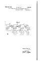
- Fig. 1 is a diagrammatic view showing one form of circuit embodying improvements of my invention with a loss producing impedance in the grid circuit, the transformers of the radio amplification stages being shielded and circuit adapted for multiple unit or single control.
- Fig. 2 is a longitudinal sectional view of one form of choke coil suitable for use as an inductive reactance according to my lnvention.
- Fig. 3 is a longitudinal sectional view showing another form of choke co-il.
- Fig. 4 is a longitudinal sectional view showing another form of choke coil.
- F ig. 5 is a diagrammatic view of another J circuit arrangement, two shielded choke coils serving as loss producing impedances and showing the separate radio frequency stages shielded from each other and'omitting the audio stages.
- Fig. 1 there is a tuned input circuit l t and two stages and 16 of radio amplification with any suitable form of tubes 17 and '18.
- the detector stage 19 may be of any suitable type; Any suitable number of audio stages of amplification suchas 20 and 21 may be employed, and any suitable form of loud speaker or other reproducing device 22. may be employed. It should also be understood that any suitable method of power supply may be applied according to my invention.
- Impeda-nces 23 and 2e are inserted in the respective grid circuits of the first two tubes. t will be understood, of course, that the invention is applicable to any number of radio stages of amplification. In some cases, it is desirable to use a similarimpedance 25 in the grid circuit of the detector, This c1rcu1t in F g. 11s especially adapted for simultaneous operation of the tuningcon-.
- densers 26,27 and 28 byany suitable form of controldiagrammatically suggested by the line. 29.
- This circuit is shown with shields, 30, 31 and 32 for the various transformers.
- i Q j The impedances 23 and 24 may be of any suitable type, such for instance, as those 7 shown in Figsi2, 3 and l.
- a simplermethod of preventing oscillations is to use a less eificientchoke coil. This may; be accomplished by placing a small amount of iron in the core.
- the formof the iron depends somewhat upon the design of the choke but either iron wire or lamina tions may be used.
- Ordinary transformer iron or wire is satisfactory inasmuch as the purpose of the-iron is merely to insert losses rather than to extend the working range of the choke coil which, of course, may be done, if necessary, by utilizing thin laminations of high frequency iron-as is well known in the art.
- the choke coils 23 and 24 are'providedwith iron cores. 7
- One form is shown indetail in Fig. 3.
- the coil 37 is wound on an insulating bobbin 38 and provided with a core 39,
- the bobbin is sufiicientlythick walledso as to space the coil away for the core and prevent capacity effect.
- an iron core choke changes" the relation of impedance to frequency over a wide range of frequenciestending to increase in effect as frequency ncreases.
- Theresistance component ofan iron core choke designed for a given receiver may have a very high value at 200 meters and gradually taper-off as desired.
- T he coil 45 is wound on an insulating bobbin 49 which is provided with an insulating bushing'50and terminals 51.
- a shield 52 of copper or other suitable metal s'urroundsthe coil and has its ends compressed on to the bushings 50.
- a radio frequency amplifier comprising the combination of an amplifying device, a tuned input circuit including an inductance and a variable capacity, an output circuit and means for preventing undesirable self-oscillations consisting of a loss producing circuit capacitively reactive over the frequency response band of the amplifier and connected i in shunt to the said variable capacity of the tuning circuit, said loss producing circuit containin a loss producing choke coil with loss producing material in its field and having an efiective resistance much greater at high frequencies than at low and in series with a small capacity.
- a radio frequency amplifier comprising the combination of an amplifying tube, a tuned input circuit including an inductance and a variable capacity, an output circuit and means for preventing undesirable self-oscillations consisting of a loss producing circuit capacitively reactive over the frequency response band of the amplifier and connected in shunt to the said variable capacity of the tuning circuit, said loss producing circuit containing a loss producing choke coil with loss producing material associated therewith and having an effective resistance much greater at high frequencies than at low, in series with a small capacity comprising the grid filament capacity of said amplifying tube.
- a radio frequency amplifier comprising the combination of an amplifying device, a tuned input circuit including an inductance and a capacity, one of which is variable, an output circuit and means for preventing undesirable self-oscillations including an inductance with associated loss producing iron and of much greater resistance at high frequencies than low frequencies within the frequency response band of the amplifier, said inductance shunted across the inductance and capacity of the tuned circuit and having capacity in series with the second mentioned inductance.
- a radio frequency amplifier system comprising a thermionic amplifying device having an input circuit with tuning means, an output circuit and means for preventing un desirable self-oscillations including a path of impedance, the effective resistance component of which varies with frequency and is composed of an iron core loss producing inductance coil in series with a capacity, said impedance path connected in shunt to said tuning means and said capacity composed of the grid to filament interelectrode capacity of said thermionic amplifying device.
- a radio frequency amplifier system comprising a thermionic amplifying device having a tuned input circuit and an output circuit and means for preventing undesirable selfoscillations including an inductance having loss producing means including an iron core, said inductance being of suitable value and located in at least one of the connecting leads between the variable tuning element and said thermionic amplifying device.
- a radio frequency amplifier system comprising a thermionic amplifying device having a tuned input circuit and an output circuit and means for preventing undesirable selfoscillations including a reactance having a loss producing core, said reactance being of suitable value and located in at least one of the connecting leads external to the tuned input circuit.
Landscapes
- Engineering & Computer Science (AREA)
- Power Engineering (AREA)
- Amplifiers (AREA)
Description
March 29, 1932. w. AULL, JR 1,851,078
GRID SUPPRESSOR FOR STABILIZING RADIOF'REQUENCY AMFLIFIERS Filed March 21. 1927 2 Sheets-Sheet 1 gl l hj l l lm hl N I INVEN'IOR March 29., 1932. v w, U L, JR 1,851,078
GRID SUPPRESSOR FOR STABILIZING RADIOFREQUENCY AMPLIFIERS I Filed Mdrch 21. 1927 2 Sheets-Sheet 2 INVENTOR Patented Mar. 29, 1932 PATENT OFFICE WILSON AULL, JR., F ASTORIA, NEW YORK GRID SUPPRESSOR FOB STABILIZING RADIOFREQUENCY AMPLIFIERS Application filed March 21, 192?. Serial No. 177,050.
This invention relates to improvements in radio receiving systems and is of particular value in connection with the prevention of undesirable self-oscillation in tuned radio frequency amplifiers of the cascade type in which a three electrode vacuum tube is used to couple two tuned circuits, the complete amplifier consisting of one or more such stages in series or cascade.
When the tuned circuits of such an amplifier are tuned by capacitance only, selfoscillation is most likely to occur at the higher frequencies and gradually decrease in intensity as the system is progressively tuned to the lower frequencies. Conversely, if the tuned circuits are arranged to be adjusted to resonance by inductance variation only, selfoscillation is more persistent at the lower frequencies, gradually decreasing in intensity as the system is progressively tuned to higher frequencies.
My invention provides a method of and means for the prevention of undesirable selfoscillations and of approximately equalizing the overall radio frequency amplification of the frequency response band in a capacitively tuned radio frequency amplifier. This is accomplished principally by utilizing loss producing impedances of various forms as will become apparent later in the specification.
As is well known in the art, condenser tuned amplifiers tend to oscillate at the higher frequencies due to undesirable electromagnetic and electrostatic coupling between the input part of the amplifier and parts of the receiver containing increased energy due to the amplifying action of the vacuum tubes and their associated circuits, Much of this type of coupling may be reduced by various means of restricting coil and condenser fields and by the proper use of shielding. Even then undesirable coupling is effected by means of the inter-electrode capacities of the vacuum tubes. Inasmuch as more energy is transferred between capacity coupled circuits at high frequencies than low, even well shielded amplifiers tend to oscillate at these frequencies if the filaments of the vacuum 50 tubes are at normal temperature and the primaries of the radio frequency amplifying transformers have enough turns to give a good transfer of enengy.
All this is well known in the art and various means have been utilized by manufacturers of broadcast receivers to prevent selfoscillation, such as inserting losses in various parts of the circuits by means of resistances of various kinds, reducing primary turns, inserting high resistance in the grid connecting wires to the vacuum tubes, etc. Such methods, while efficacious in preventing oscillation at the higher frequencies have the disadvantage that they reduce amplification at the lower frequencies and as a consequence a receiver designed for operation from 200 to 600 meters, for example, falls off in sensitivity above perhaps 450 meters.
My invention in connection with condenser tuned circuits consists in inserting a loss producing impedance of suitable value in the grid leads of the radio frequency amplifier tubes or in the connecting wire between the grid tuning circuit and the filament circuit. In either position, such an impedance, better known in the art as a high frequency choke coil, when properly designed in relation to the constants of the remainder of the amplifier, has an impedance that varies with frequency and may have a resistance component to coincide with that necessary to prevent oscillation at the higher frequencies but be almost negligible at the lower frequencies where the tendency toward self-oscillation is relatively small.-
Fig. 1 is a diagrammatic view showing one form of circuit embodying improvements of my invention with a loss producing impedance in the grid circuit, the transformers of the radio amplification stages being shielded and circuit adapted for multiple unit or single control.
Fig. 2 is a longitudinal sectional view of one form of choke coil suitable for use as an inductive reactance according to my lnvention.
Fig. 3 is a longitudinal sectional view showing another form of choke co-il.
Fig. 4 is a longitudinal sectional view showing another form of choke coil.
F ig. 5 is a diagrammatic view of another J circuit arrangement, two shielded choke coils serving as loss producing impedances and showing the separate radio frequency stages shielded from each other and'omitting the audio stages.
In the circuit, shown in Fig. 1 there is a tuned input circuit l t and two stages and 16 of radio amplification with any suitable form of tubes 17 and '18.
The detector stage 19 may be of any suitable type; Any suitable number of audio stages of amplification suchas 20 and 21 may be employed, and any suitable form of loud speaker or other reproducing device 22. may be employed. It should also be understood that any suitable method of power supply may be applied according to my invention.
Impeda-nces 23 and 2e are inserted in the respective grid circuits of the first two tubes. t will be understood, of course, that the invention is applicable to any number of radio stages of amplification. In some cases, it is desirable to use a similarimpedance 25 in the grid circuit of the detector, This c1rcu1t in F g. 11s especially adapted for simultaneous operation of the tuningcon-.
densers 26,27 and 28 byany suitable form of controldiagrammatically suggested by the line. 29. This circuit is shown with shields, 30, 31 and 32 for the various transformers. i Q j The impedances 23 and 24 may be of any suitable type, such for instance, as those 7 shown in Figsi2, 3 and l.
inductance of small diameter with a coil 35' wound withfine wire on an insulating tube 36.
7 A simplermethod of preventing oscillations is to use a less eificientchoke coil. This may; be accomplished by placing a small amount of iron in the core. The formof the iron depends somewhat upon the design of the choke but either iron wire or lamina tions may be used. Ordinary transformer iron or wire is satisfactory inasmuch as the purpose of the-iron is merely to insert losses rather than to extend the working range of the choke coil which, of course, may be done, if necessary, by utilizing thin laminations of high frequency iron-as is well known in the art.
In the circuit of Fig. 1, the choke coils 23 and 24 are'providedwith iron cores. 7 One form is shown indetail in Fig. 3. r The coil 37 is wound on an insulating bobbin 38 and provided with a core 39, The bobbin is sufiicientlythick walledso as to space the coil away for the core and prevent capacity effect.
The use of an iron core choke changes" the relation of impedance to frequency over a wide range of frequenciestending to increase in effect as frequency ncreases. Theresistance component ofan iron core choke designed for a given receiver may have a very high value at 200 meters and gradually taper-off as desired.
In the circuit of Fig. 5 the various tubes 40, 41, 42 and their associated circuits are shielded from each other by shields such as 43, 44 and 45. The chokes 46 and {T7 are shielded from the associated tuning devices in the same compartment; Suchshielded chokes are shown in Fig. 4.
. T he coil 45 is wound on an insulating bobbin 49 which is provided with an insulating bushing'50and terminals 51.
A shield 52 of copper or other suitable metal s'urroundsthe coil and has its ends compressed on to the bushings 50.
I have found that an easy laboratory method of obtaining the form of impedance variation necessary in a given receiver design consists in plotting a curve of wavelength or frequency or dial divisions as abscissae against the amount of resistance just necessary for stable operation as ordinates,
For example, with a given laboratory re ceiver of the general type shown in Fig. l and which is satisfactory as regards correct primary turns for amplification, selectivity,
etc., it. might be found that self-oscillation occurs'with the chokecoils cut out, when all tuning circuitsare tuned to the same period 1- and that this effect takes place fromO to 50 divisions on tunmgdials graduated from O to 100 divisions. 1 The desired curve can easily be plotted by inserting a variable re- I sistance of say, to 2500 ohms'in the grid lead of each of'th'e' radio frequency tubes and adjusting the resistances for best" operation, usually keeping them at about the same value as the circuits are adjusted for satisfactory reception at various wavelengths, perhaps every three divisions. V a
H In such a receiver the resistance necessary is large; around the lower part of'the" scale and tapers ofi' gradually to the wavelength atwhich no'oscillation takes place with all necessary to suppress oscillation at the'highest frequency. This would of necessity reduce amplification at lower frequencies where the high resistance isunnecessary. A choke coil, properly designed for a given receiver is thus automatic in" action, having the effective resistancevalues necessary at the higher frequencies and much low ervalues at the lower frequencies. a 1 1 While I have illustrated my invention in connection with a simple form of tuned radio L frequency circuit, I do'n'ot wish my invention ing a tuned input circuit and an output cir cuit and means for preventing undesirable self oscillations including an inductance having a magnetic loss producing means, said inductance being of suitable value and located in at least one of the connecting leads external to the tuned input circuit.
2. A radio frequency amplifier comprising the combination of an amplifying device, a tuned input circuit including an inductance and a variable capacity, an output circuit and means for preventing undesirable self-oscillations consisting of a loss producing circuit capacitively reactive over the frequency response band of the amplifier and connected i in shunt to the said variable capacity of the tuning circuit, said loss producing circuit containin a loss producing choke coil with loss producing material in its field and having an efiective resistance much greater at high frequencies than at low and in series with a small capacity.
3. A radio frequency amplifier comprising the combination of an amplifying tube, a tuned input circuit including an inductance and a variable capacity, an output circuit and means for preventing undesirable self-oscillations consisting of a loss producing circuit capacitively reactive over the frequency response band of the amplifier and connected in shunt to the said variable capacity of the tuning circuit, said loss producing circuit containing a loss producing choke coil with loss producing material associated therewith and having an effective resistance much greater at high frequencies than at low, in series with a small capacity comprising the grid filament capacity of said amplifying tube.
4. A radio frequency amplifier comprising the combination of an amplifying device, a tuned input circuit including an inductance and a capacity, one of which is variable, an output circuit and means for preventing undesirable self-oscillations including an inductance with associated loss producing iron and of much greater resistance at high frequencies than low frequencies within the frequency response band of the amplifier, said inductance shunted across the inductance and capacity of the tuned circuit and having capacity in series with the second mentioned inductance.
5. A radio frequency amplifier system comprising a thermionic amplifying device having an input circuit with tuning means, an output circuit and means for preventing un desirable self-oscillations including a path of impedance, the effective resistance component of which varies with frequency and is composed of an iron core loss producing inductance coil in series with a capacity, said impedance path connected in shunt to said tuning means and said capacity composed of the grid to filament interelectrode capacity of said thermionic amplifying device.
6. A radio frequency amplifier system comprising a thermionic amplifying device having a tuned input circuit and an output circuit and means for preventing undesirable selfoscillations including an inductance having loss producing means including an iron core, said inductance being of suitable value and located in at least one of the connecting leads between the variable tuning element and said thermionic amplifying device.
7. A radio frequency amplifier system comprising a thermionic amplifying device having a tuned input circuit and an output circuit and means for preventing undesirable selfoscillations including a reactance having a loss producing core, said reactance being of suitable value and located in at least one of the connecting leads external to the tuned input circuit.
WILSON AULL, JR.
Priority Applications (1)
| Application Number | Priority Date | Filing Date | Title |
|---|---|---|---|
| US177050A US1851078A (en) | 1927-03-21 | 1927-03-21 | Grid suppressor for stabilizing radiofrequency amplifiers |
Applications Claiming Priority (1)
| Application Number | Priority Date | Filing Date | Title |
|---|---|---|---|
| US177050A US1851078A (en) | 1927-03-21 | 1927-03-21 | Grid suppressor for stabilizing radiofrequency amplifiers |
Publications (1)
| Publication Number | Publication Date |
|---|---|
| US1851078A true US1851078A (en) | 1932-03-29 |
Family
ID=22646974
Family Applications (1)
| Application Number | Title | Priority Date | Filing Date |
|---|---|---|---|
| US177050A Expired - Lifetime US1851078A (en) | 1927-03-21 | 1927-03-21 | Grid suppressor for stabilizing radiofrequency amplifiers |
Country Status (1)
| Country | Link |
|---|---|
| US (1) | US1851078A (en) |
-
1927
- 1927-03-21 US US177050A patent/US1851078A/en not_active Expired - Lifetime
Similar Documents
| Publication | Publication Date | Title |
|---|---|---|
| US2555906A (en) | Tunable amplifier having a predetermined band-pass characteristic throughout its range | |
| US2661459A (en) | Band pass filter circuit | |
| US2111373A (en) | Permeability-tuned device | |
| US1791236A (en) | Electrical circuit and transformer therefor | |
| US2404640A (en) | Ultra high frequency signaltranslating apparatus | |
| US2084740A (en) | Filter circuit | |
| US1851078A (en) | Grid suppressor for stabilizing radiofrequency amplifiers | |
| US2165575A (en) | High-frequency coupling device | |
| US2452560A (en) | Band-pass transformer | |
| US1690228A (en) | High-frequency transformer | |
| US2276699A (en) | Superheterodyne receiver | |
| US2290825A (en) | Permeability tuning loop antenna | |
| US2038294A (en) | Coupling system | |
| US2250277A (en) | Coupled circuit regenerative receiving system | |
| US2125119A (en) | Coupling transformer | |
| US2082587A (en) | High-frequency circuit | |
| US2505516A (en) | Permeability tuned receiver circuits | |
| US2267047A (en) | Signal collecting system for radio receivers and the like | |
| US1650353A (en) | Wave signaling system | |
| US2154327A (en) | Signal amplifier | |
| US2668198A (en) | Tuner for television receivers | |
| US2158251A (en) | High-frequency radio amplifying circuits | |
| US2402260A (en) | Permeability tuned short-wave spread-band receiver | |
| US2289594A (en) | Coupled loop collector circuit | |
| US3209274A (en) | Electronically tunable transistor interstage network |