US1851077A - Cooler - Google Patents
Cooler Download PDFInfo
- Publication number
- US1851077A US1851077A US553625A US55362531A US1851077A US 1851077 A US1851077 A US 1851077A US 553625 A US553625 A US 553625A US 55362531 A US55362531 A US 55362531A US 1851077 A US1851077 A US 1851077A
- Authority
- US
- United States
- Prior art keywords
- casing
- pipes
- top wall
- fluid
- inlet pipes
- Prior art date
- Legal status (The legal status is an assumption and is not a legal conclusion. Google has not performed a legal analysis and makes no representation as to the accuracy of the status listed.)
- Expired - Lifetime
Links
- 239000012530 fluid Substances 0.000 description 27
- XLYOFNOQVPJJNP-UHFFFAOYSA-N water Substances O XLYOFNOQVPJJNP-UHFFFAOYSA-N 0.000 description 12
- 230000015572 biosynthetic process Effects 0.000 description 9
- 238000005755 formation reaction Methods 0.000 description 9
- 230000004048 modification Effects 0.000 description 6
- 238000012986 modification Methods 0.000 description 6
- 238000001816 cooling Methods 0.000 description 4
- 238000007599 discharging Methods 0.000 description 4
- 239000011521 glass Substances 0.000 description 3
- 239000000498 cooling water Substances 0.000 description 2
- 238000012423 maintenance Methods 0.000 description 2
- 239000000463 material Substances 0.000 description 2
- 241001080526 Vertica Species 0.000 description 1
- 238000010276 construction Methods 0.000 description 1
- 238000004519 manufacturing process Methods 0.000 description 1
Images
Classifications
-
- C—CHEMISTRY; METALLURGY
- C03—GLASS; MINERAL OR SLAG WOOL
- C03B—MANUFACTURE, SHAPING, OR SUPPLEMENTARY PROCESSES
- C03B15/00—Drawing glass upwardly from the melt
- C03B15/02—Drawing glass sheets
Definitions
- COOLER 5 SheetS-Sheet 3 Filed July 28, 1931 Patented Mar. 29, 1932 WILLIAM: M. ARCK, 'OF MOUNT VERNION; 053210 doomn efliciency of cooling apparatu-s of this kind is TI enhanced, the o eration and maintenance of the same 'is re uced' in ⁇ cost, and superior "Work is renderedpossible, With consequent economic advantages; f i 'It' is also an object of this invention to pro vide a coolerof the' type described Whichis ver' cheap to manufacture andinstall and which is eomposed of no moving parts ,and which issimple anddurable in Construction, and'is adapted'to'be positioned andinstalled i 90 in various types of glass sheet manufacturin machines.
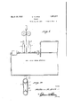
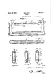
- v hse 'and' otherobjects of the'inve'tion, its'nature and itscombinaton and a rrange- 'ment of 'parte Will be readily understoodhy 7:5 anyone acquainted With the art t-o' which this 'invention rlates upon' 'consulting the fol- 'lowng description of the fdrawings in 'Whchri ' Figure l isa seetion'al View through a' glass sheet ina-king machine 'showing the positioning of apairof the coolers of the nventon with respect-thereto Fig. :2 is a 'longitudinal vertioal section ;through one tvpe of the coolers of my 'invention.
- i Fig. 3 is a horizontal sectional View taken a pproXimately on the ⁇ line ⁇ 3-3 andlooking upwardly in Fig. 2, and u e j ig. 4: is a horizontal sectional View taken approximately on the line 4-4 totFig. 2,
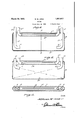
- i Fig. - is a transverse vertical sectiohal view taken 'approximately on the line :13 'of Fig and i i v Fig 6 isa longitudnal 'vertical sectional 'View of a. modification of Fig. Q. ,2
- Fig. 8 is a longitudinal vertical seetional i view through a further modification of Fig.2. 3 F
- Fig, 9 is a tra'sverse Vertical sectonal View through a still further modification similar to that shown in Fig, 2;
- Fig; 10 is a sectio'nal View similarto Fig. 9, i
- the casing 5 of the devee of the in'vention is e closed casing of a height approximately -00 three times the dimension of its Width; and of generally elongated form; It is adapted jto V he usually placed on its lower edge --asseen ⁇ -n Fig. 1, and properly spaced closely with the Work.
- the rincipal 'functionof the deice is to-'present the greatest cooling *efi'e'ct possible in the j compass provided', and 'airrangement is made to Convey cold waterlor artifi cally cooled'air orother fluid under presi sure ntothe casing 5 so that itstrkes against T-0 thehottom, and presents'the greatest cooling efi'ect at the bottom edge, and the Water or air is expelled on at the top of the casi'ngfthej point at which the wa'rnest water or :air i will be present during' the circulation of Water through the interier: ⁇ I
- Fig. 9 a modification of Fig. 2 is' shown in which the entire structure is identical with that shown'in Figs. 2 and 5 and' also in Fig. 3, but there is an addition to the lower wall 8 in the form of a ridge or longitudinal projection 15 which is alined with the slots 11 in the horizontal ppe of the inlet condnits.
- FIG. 6 will show a modiflcation in which the outlet Conduit is identical .with that of the form shown in Fig. 2, the casing a being identical in formation.
- the inlet pipes (i'a with their vertical portions 9a also ⁇ extend toa point near the lower wall 8a,jbut instead of having a horizontal pipe like that of-lO in F ig.
- the portions 9@ ter- I minate in elhows 16, and horizontally directed, so that the incoming water or air is not directly 'impinged against the bottom Wall 8a, but, since equal pressures of water or air are coming into the pipes 6c, there will be produced an equal distribution of pressure against the bottom wall 8a as the result of the coming of the streams from the elhows 16.
- the outlet Conduit 136 is the same as the outlet conduits of the forms already described, andthe casing 56 is also identical with the structure, as is the placement of the inlet pipes 66. In thisform,
- the vertical portions 96 depending from the inlet pipes 66 do not eXtend downwardly as :tar as they do in the forms of the invention already described, but theystop short at a point just under the Conduit 136 where they are provided with downwardly 'and angularly directed nozzles 17, so as to impinge a diagonal stream of water or air against opposite corners of the lower part of the casing 56.
- Fig. 1'0 there is disclosed a Still further form of the invention in which the casing is provided with the inlet and discharge pipes and 120 arranged as in the other forms of the invention, but they are welded to the top wall 7 c and do not project into the casing, but simply are communicated therewith.
- the inlet pipes 60 project to thebottom of the casing as in the forms shown in Figs. 6 and 2.
- longitudinally halved pipes are welded in the upper and lower part of the casing 50 as indicated 17 and 18 and they are provided with facing slots 19 and ,20.
- the inlet pipes 60 go to the casing in the manner described and communicate with the lower pipe 18.
- a cooler of the type described comprising an elongated, narrow, closed casing taller than it is wide, a pair of fluid pressure inlet pipes connected to and having communication with the interior of the casing through the top wall of the casing, a vertical downward extension on each of said inlet pipes within the casing, pair of outlet pipes also connected to and having communication through the top wall of the casing, the lower portionsof said inlet pipes having fluid distributing means to evenly distribute fluid under pressure against the loWerwall of the casing throughout its length, and outlet means close to the top wall in the interior of the casing connected with said outlet pipes for discharging the fluid contents of the casng.
- a cooler of the type described comprising an elongated, narrow closed casing, taller than it is wide, a pair of fluid pressure inlet pipes connected to and having communication with the interior of the casing; through the top wall of the casng, a vertical downward extension on each of said inletpipes within the casing, a pair of outlet-pipes also connected to and having communication through the top wall of the casing, the lower portions of said inlet pipes-having fluid dis ⁇ tributing means to evenly distribute fluid said fluid distributing' means comprising a horizontal tubular formation formed With an opening in one side thereof.
- a cool-er of the'type described comprising an elongated, narroW closed casing, taller than it is wide, a .pair of fluid pressure inlet pipes connected to and having communication with the interior of the casing, ⁇ through the top wall of the casing, a vertical down- Ward extension on each of said inlet pipes within the casing, a pair of outlet pipes also connected to and having communication through the top wall of the casing the lower portions of said inlet pipes having fluid distributing means to evenly distribute fluid under pressure against' the lower wall of the casing throughout its length, outlet means close to the top Wall in the interior of the casing connected with said outlet pipes for discharging the fluid contents of thecasing, said fluid distributing means comprising a horizontal tubular formation for-med with an opening in one side thereof, and said outlet means comprising a horizontal tubular formation having an opening in one side.
- a cooler of the type described comprising an elongated, narrow, closed casing taller than it is wide, a pair of fluid pressure inlet pipes connected to and having communication with the interior of the casing through the top Wall of the casing, a vertical downward extension on each of said inletpipes horizontal tubular formation forned with an 70 'opening in one side thereof, said outlet means comprising a horizontal tubular formation having an opening in one side thereo-f, said tubular formations being constructed integral with the Walls of the casing.
- a cooler of the type described compris- 1 ing an elongated, narrow, closed casing, tallerthan it is wide, a pair of fluid pressure inlet' pipes connected to and having 'communication With the interior of the casing through the top Wall of the casing, a vertical down- Ward extension on each of said inlet pipes withinthe casing, a pair' of outlet pipes also connected to and having communication through the top wall of the casing, the lower portions of said inlet pipes having fluid distributing means' to evenly distributej fluid under pressure against the lower part of the ca sing throughout its length, outlet .means close to the top wall in the interior of the casing connected With said outlet pipes for.
- said fluid distributing means comprsing a horizontal' tubular formation formed with 95 an opening in one side thereof, said tubular' formations being spaced close to the top and bottom wallsof the casing;
- a pair of outlet pipes also connected to and having communication through the top wall of the casing, the lower oportions of said inlet pipes having fluid distributing means to evenly distribute'fluid under pressure against the lower wall; of the casing throughout its length, outlet means close tothe top wall in the interior of the casing connected
- said outlet pipes for' discharging the fluid contents of thecasing, 'said fluid distributing means' comprising inwardly clirected nozzles onthe lower portions of the said downward extensions 'or the inlet pipes.
- a cooler of the type described comprising an elongated, narrow, closed casing
- a pair of fluid pressure t inlet pipes connected to and having communication With the interior of the casing, through the top wall of the casing, a vertical downward extension on each of said inlet pipes within the casing, a pair of outlet pipes also connected to and having communication through the top wall of the casing, the. lower portions of said inlet pipes having fluid distributing meansto evenly distrihute fluid
Landscapes
- Chemical & Material Sciences (AREA)
- Engineering & Computer Science (AREA)
- Materials Engineering (AREA)
- Organic Chemistry (AREA)
- Heat-Exchange Devices With Radiators And Conduit Assemblies (AREA)
Description
W. M. ARCK March 29, 1932.
COOLER Filed July 28. 1931 3 Sheets-Sheet W. M. ARCK March 29, 1932.
COOLER 5 SheetS-Sheet 3 Filed July 28, 1931 Patented Mar. 29, 1932 WILLIAM: M. ARCK, 'OF MOUNT VERNION; 053210 doomn efliciency of cooling apparatu-s of this kind is TI enhanced, the o eration and maintenance of the same 'is re uced' in` cost, and superior "Work is renderedpossible, With consequent economic advantages; f i 'It' is also an object of this invention to pro vide a coolerof the' type described Whichis ver' cheap to manufacture andinstall and which is eomposed of no moving parts ,and which issimple anddurable in Construction, and'is adapted'to'be positioned andinstalled i 90 in various types of glass sheet manufacturin machines. v hse 'and' otherobjects of the'inve'tion, its'nature and itscombinaton and a rrange- 'ment of 'parte Will be readily understoodhy 7:5 anyone acquainted With the art t-o' which this 'invention rlates upon' 'consulting the fol- 'lowng description of the fdrawings in 'Whchri 'Figure l isa seetion'al View through a' glass sheet ina-king machine 'showing the positioning of apairof the coolers of the nventon with respect-thereto Fig. :2 is a 'longitudinal vertioal section ;through one tvpe of the coolers of my 'invention.
i Fig. 3 is a horizontal sectional View taken a pproXimately on the `line`3-3 andlooking upwardly in Fig. 2, and u e j ig. 4: is a horizontal sectional View taken approximately on the line 4-4 totFig. 2,
`looking; downwardly.
i Fig. -is a transverse vertical sectiohal view taken 'approximately on the line :13 'of Fig and i i v Fig 6 isa longitudnal 'vertical sectional 'View of a. modification of Fig. Q. ,2
7 is e transverse vertical sectional :View taken appro imately on the-line 7 -7 1931; Serial No. 553325.
Fig. 8 is a longitudinal vertical seetional i view through a further modification of Fig.2. 3 F
Fig, 9 is a tra'sverse Vertical sectonal View through a still further modification similar to that shown in Fig, 2;
" Fig; 10 is a sectio'nal View similarto Fig. 9, i
in a still further modification. u 1 e 'i The casing 5 of the devee of the in'vention is e closed casing of a height approximately -00 three times the dimension of its Width; and of generally elongated form; It is adapted jto V he usually placed on its lower edge --asseen `-n Fig. 1, and properly spaced closely with the Work. The rincipal 'functionof the deice is to-'present the greatest cooling *efi'e'ct possible in the j compass provided', and 'airrangement is made to Convey cold waterlor artifi cally cooled'air orother fluid under presi sure ntothe casing 5 so that itstrkes against T-0 thehottom, and presents'the greatest cooling efi'ect at the bottom edge, and the Water or air is expelled on at the top of the casi'ngfthej point at which the wa'rnest water or :air i will be present during' the circulation of Water through the interier:` I
` In order to 'accomplish the circulaton of ;Water or air according to this plan', there'is provided an arrangenent of a pair of'inlet ppes 6 enterng the top'wall of the casiiig, g
curvate in the crosssectim` as `is thebottom \vall'8,- the2 top Wall being designated by the 'nunerljg r In the form of device shown in Fig 2,' 'the nlet pipes `6jhave portions- 9 pro-;385 .jectin'g vertica lly from the casng, 'and a hor- ,izontalportion lOis 'formed integral wth the e lower ends of the vertical portins'Qandas near the bottom Wall 8 as isconsistent with theefiect'desired. v 'The bottom side of the'horizontal portion 10 is'provded With anelongated 'slot 11 "of syminetrical proportions and are 'sofer-med I asto provide that as equal pressures of water I I or air are delivered through the uprightjpor tions 9 of the pipes 6, equal pressures'of water or' air Will be expelled' thru the "slotll against equally i Outlet pipes 12 are projected through the top wall 7 of the casing and between the inlet pipes 6 and the inner ends of the pipes 12 have a horizontal pipe 13 placed as close to the upper wall 7 as may be Conveniently done. A slot 14 is placed the length of the upward side of the horizontal pipe 13, and so proportionecl as to properly withdraw the water or air from the casing 5 at the highest point of the casing, where the water or air is warmest.
It is essential for the successful operation of the forms of the device shown in the drawings that the pressure in each inlet pipe 6 be equalized, so as to equalize the impinging of the cooling water or air against every point of the lower wall 8 so as to equally cool the same throughout its length to prevent cold lines in the finished glass sheet.
The maintenance of equal pressures will insure absolutely the even cooling desired in this type of work. I Beferrngto Fig. 9, a modification of Fig. 2 is' shown in which the entire structure is identical with that shown'in Figs. 2 and 5 and' also in Fig. 3, but there is an addition to the lower wall 8 in the form of a ridge or longitudinal projection 15 which is alined with the slots 11 in the horizontal ppe of the inlet condnits.
Reference to Fig. 6 will show a modiflcation in which the outlet Conduit is identical .with that of the form shown in Fig. 2, the casing a being identical in formation. The inlet pipes (i'a with their vertical portions 9a also `extend toa point near the lower wall 8a,jbut instead of having a horizontal pipe like that of-lO in F ig. 2, the portions 9@ ter- I minate in elhows 16, and horizontally directed, so that the incoming water or air is not directly 'impinged against the bottom Wall 8a, but, since equal pressures of water or air are coming into the pipes 6c, there will be produced an equal distribution of pressure against the bottom wall 8a as the result of the coming of the streams from the elhows 16. Referring to Fig 8, the outlet Conduit 136 is the same as the outlet conduits of the forms already described, andthe casing 56 is also identical with the structure, as is the placement of the inlet pipes 66. In thisform,
however, the vertical portions 96 depending from the inlet pipes 66 do not eXtend downwardly as :tar as they do in the forms of the invention already described, but theystop short at a point just under the Conduit 136 where they are provided with downwardly 'and angularly directed nozzles 17, so as to impinge a diagonal stream of water or air against opposite corners of the lower part of the casing 56.
The resultant of equal pressures of water or air coming through the pipes 66 in this form causes to ,impinge equally along the bottom wall 86 the cooling water or air. Referring to Fig. 1'0, there is disclosed a Still further form of the invention in which the casing is provided with the inlet and discharge pipes and 120 arranged as in the other forms of the invention, but they are welded to the top wall 7 c and do not project into the casing, but simply are communicated therewith. v
The inlet pipes 60 project to thebottom of the casing as in the forms shown in Figs. 6 and 2. In the form shown in Fig. 10 longitudinally halved pipes are welded in the upper and lower part of the casing 50 as indicated 17 and 18 and they are provided with facing slots 19 and ,20. The inlet pipes 60 go to the casing in the manner described and communicate with the lower pipe 18.
' assembly, as well as certain variations in structure and materials s possible wthn the concept of the invention, it is to be definitely understood that I do not desire to limit the application of this invention to the particular modifications set out hereinto illustrate the principles thereof, and any change or changes may be made in material and structure and arrangement of parts consistent with the spiritand scope of the invention. Having thus described my invention, what Iclaimasnewisz- 1. A cooler of the type described comprising an elongated, narrow, closed casing taller than it is wide, a pair of fluid pressure inlet pipes connected to and having communication with the interior of the casing through the top wall of the casing, a vertical downward extension on each of said inlet pipes within the casing, pair of outlet pipes also connected to and having communication through the top wall of the casing, the lower portionsof said inlet pipes having fluid distributing means to evenly distribute fluid under pressure against the loWerwall of the casing throughout its length, and outlet means close to the top wall in the interior of the casing connected with said outlet pipes for discharging the fluid contents of the casng.
2. A cooler of the type described comprising an elongated, narrow closed casing, taller than it is wide, a pair of fluid pressure inlet pipes connected to and having communication with the interior of the casing; through the top wall of the casng, a vertical downward extension on each of said inletpipes within the casing, a pair of outlet-pipes also connected to and having communication through the top wall of the casing, the lower portions of said inlet pipes-having fluid dis` tributing means to evenly distribute fluid said fluid distributing' means comprising a horizontal tubular formation formed With an opening in one side thereof.
3. A cool-er of the'type described comprising an elongated, narroW closed casing, taller than it is wide, a .pair of fluid pressure inlet pipes connected to and having communication with the interior of the casing,` through the top wall of the casing, a vertical down- Ward extension on each of said inlet pipes within the casing, a pair of outlet pipes also connected to and having communication through the top wall of the casing the lower portions of said inlet pipes having fluid distributing means to evenly distribute fluid under pressure against' the lower wall of the casing throughout its length, outlet means close to the top Wall in the interior of the casing connected with said outlet pipes for discharging the fluid contents of thecasing, said fluid distributing means comprising a horizontal tubular formation for-med with an opening in one side thereof, and said outlet means comprising a horizontal tubular formation having an opening in one side.
thereof.
4. A cooler of the type described comprising an elongated, narrow, closed casing taller than it is wide, a pair of fluid pressure inlet pipes connected to and having communication with the interior of the casing through the top Wall of the casing, a vertical downward extension on each of said inletpipes horizontal tubular formation forned with an 70 'opening in one side thereof, said outlet means comprising a horizontal tubular formation having an opening in one side thereo-f, said tubular formations being constructed integral with the Walls of the casing.
6. A cooler of the type described compris- 1 ing an elongated, narrow, closed casing, tallerthan it is wide, a pair of fluid pressure inlet' pipes connected to and having 'communication With the interior of the casing through the top Wall of the casing, a vertical down- Ward extension on each of said inlet pipes withinthe casing, a pair' of outlet pipes also connected to and having communication through the top wall of the casing, the lower portions of said inlet pipes having fluid distributing means' to evenly distributej fluid under pressure against the lower part of the ca sing throughout its length, outlet .means close to the top wall in the interior of the casing connected With said outlet pipes for. discharging the fluid contents of the 'casing, said fluid distributing means comprsing a horizontal' tubular formation formed with 95 an opening in one side thereof, said tubular' formations being spaced close to the top and bottom wallsof the casing; In testimony whereof I aiiix my signature.
VVILLIAM VM. ARCK. wo
within the casing, a pair of outlet pipes also connected to and having communication through the top wall of the casing, the lower oportions of said inlet pipes having fluid distributing means to evenly distribute'fluid under pressure against the lower wall; of the casing throughout its length, outlet means close tothe top wall in the interior of the casing connected With said outlet pipes for' discharging the fluid contents of thecasing, 'said fluid distributing means' comprising inwardly clirected nozzles onthe lower portions of the said downward extensions 'or the inlet pipes. e
5. A cooler of the type described comprising an elongated, narrow, closed casing,
taller than it is Wide, a pair of fluid pressure t inlet pipes connected to and having communication With the interior of the casing, through the top wall of the casing, a vertical downward extension on each of said inlet pipes within the casing, a pair of outlet pipes also connected to and having communication through the top wall of the casing, the. lower portions of said inlet pipes having fluid distributing meansto evenly distrihute fluid
Priority Applications (1)
| Application Number | Priority Date | Filing Date | Title |
|---|---|---|---|
| US553625A US1851077A (en) | 1931-07-28 | 1931-07-28 | Cooler |
Applications Claiming Priority (1)
| Application Number | Priority Date | Filing Date | Title |
|---|---|---|---|
| US553625A US1851077A (en) | 1931-07-28 | 1931-07-28 | Cooler |
Publications (1)
| Publication Number | Publication Date |
|---|---|
| US1851077A true US1851077A (en) | 1932-03-29 |
Family
ID=24210117
Family Applications (1)
| Application Number | Title | Priority Date | Filing Date |
|---|---|---|---|
| US553625A Expired - Lifetime US1851077A (en) | 1931-07-28 | 1931-07-28 | Cooler |
Country Status (1)
| Country | Link |
|---|---|
| US (1) | US1851077A (en) |
Cited By (1)
| Publication number | Priority date | Publication date | Assignee | Title |
|---|---|---|---|---|
| US2703224A (en) * | 1951-02-14 | 1955-03-01 | Arkell And Smiths | Printing press cooling roll |
-
1931
- 1931-07-28 US US553625A patent/US1851077A/en not_active Expired - Lifetime
Cited By (1)
| Publication number | Priority date | Publication date | Assignee | Title |
|---|---|---|---|---|
| US2703224A (en) * | 1951-02-14 | 1955-03-01 | Arkell And Smiths | Printing press cooling roll |
Similar Documents
| Publication | Publication Date | Title |
|---|---|---|
| US2558222A (en) | Deaerating hot well | |
| US1851077A (en) | Cooler | |
| US3229761A (en) | Spur tube with alternate oppositely directed orifices | |
| US2195449A (en) | Water cooling and carbonating device | |
| US3895676A (en) | Heat exchanger distributor | |
| US1410561A (en) | Fluid condensing or heating device | |
| US1372135A (en) | Water-cooler | |
| US1861484A (en) | Concealed heater | |
| US2376505A (en) | Heat exchange apparatus | |
| US840195A (en) | Bosh-plate. | |
| US156974A (en) | Improvement in radiators for steam-heaters | |
| US1721251A (en) | Condenser preheater | |
| US586766A (en) | Alfred seale haslam | |
| US1936166A (en) | Method of connecting pipes and improved pipe-connecting system | |
| USRE8799E (en) | Improvement in plungers for pressing glass | |
| US238529A (en) | Foueth to geobge t | |
| US1983301A (en) | Cooling apparatus | |
| US883339A (en) | Liquid-heating apparatus. | |
| US365758A (en) | Radiator | |
| US1153273A (en) | Preheater. | |
| US223661A (en) | David van hovefbebg | |
| US183384A (en) | Improvement in milk-coolers | |
| US734975A (en) | Apparatus for supplying cool air to buildings. | |
| US661837A (en) | Sizing-kettle. | |
| GB353657A (en) | Improvements in or relating to surface apparatus for heating or cooling liquids |