US1851075A - Seal ring - Google Patents
Seal ring Download PDFInfo
- Publication number
- US1851075A US1851075A US274586A US27458628A US1851075A US 1851075 A US1851075 A US 1851075A US 274586 A US274586 A US 274586A US 27458628 A US27458628 A US 27458628A US 1851075 A US1851075 A US 1851075A
- Authority
- US
- United States
- Prior art keywords
- ring
- bushing
- hub
- bearing
- shaft
- Prior art date
- Legal status (The legal status is an assumption and is not a legal conclusion. Google has not performed a legal analysis and makes no representation as to the accuracy of the status listed.)
- Expired - Lifetime
Links
- 238000007789 sealing Methods 0.000 description 6
- 239000000314 lubricant Substances 0.000 description 4
- 239000002131 composite material Substances 0.000 description 2
- 238000010276 construction Methods 0.000 description 2
- 102100035683 Axin-2 Human genes 0.000 description 1
- 101700047552 Axin-2 Proteins 0.000 description 1
- 229910000906 Bronze Inorganic materials 0.000 description 1
- 229910000831 Steel Inorganic materials 0.000 description 1
- 239000011324 bead Substances 0.000 description 1
- 239000010974 bronze Substances 0.000 description 1
- 238000004891 communication Methods 0.000 description 1
- 230000006835 compression Effects 0.000 description 1
- 238000007906 compression Methods 0.000 description 1
- KUNSUQLRTQLHQQ-UHFFFAOYSA-N copper tin Chemical compound [Cu].[Sn] KUNSUQLRTQLHQQ-UHFFFAOYSA-N 0.000 description 1
- 238000005461 lubrication Methods 0.000 description 1
- 238000012856 packing Methods 0.000 description 1
- 108010085990 projectin Proteins 0.000 description 1
- 239000007779 soft material Substances 0.000 description 1
- 239000010959 steel Substances 0.000 description 1
Images
Classifications
-
- F—MECHANICAL ENGINEERING; LIGHTING; HEATING; WEAPONS; BLASTING
- F16—ENGINEERING ELEMENTS AND UNITS; GENERAL MEASURES FOR PRODUCING AND MAINTAINING EFFECTIVE FUNCTIONING OF MACHINES OR INSTALLATIONS; THERMAL INSULATION IN GENERAL
- F16J—PISTONS; CYLINDERS; SEALINGS
- F16J15/00—Sealings
- F16J15/16—Sealings between relatively-moving surfaces
- F16J15/34—Sealings between relatively-moving surfaces with slip-ring pressed against a more or less radial face on one member
- F16J15/38—Sealings between relatively-moving surfaces with slip-ring pressed against a more or less radial face on one member sealed by a packing
Definitions
- This invention relates to a composite seal ring and more especially to an improvement on my copending application filed January 28, 1928, Serial Number 250,224.
- One of the objects of the invention is to provide a composite seal ring designed primarily for use within the hub of a flywheel or other structure rotatable with the shaft in the bearing to be sealed.
- a further object is to provide a seal ring which,,be causeof.its'. location in the rotatable member on the shaft, can be easily replaced and repaired without the necessity of disma'ntling the shaft.
- a further object is to provide a seal ring which permits ample lubrication of the bearing and possesses all of the advantages 1ncident to the use of the ring disclosed in my application before referred to.
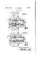
- Figure 1 is a section through the seal mug and adjacent parts.
- Figure 2 is a snmlar v1ew showinga slight ly modified construction.
- FIG. 1 designates a capadapted to close .an aperture in a crank c ase, th'is cap roviding a bearing for a crank shaft 2 an being suitablylined by a bushing 3.
- This bushing may be formed with an annular flange 4 at its inner endadapted to lap the inner end of the bearing member or cap 1 and the outer end of the bushing is adapted to pro ject slightly beyond the outer end of the bearing member 1 to present a smooth wear 'surfaceindicated (generally at 5, Oil grooves 6 may be ,extende longitudinally within'the bushing, these grooves being openaat' their 1928. Serial N0. 274,586.
- Flange 9 is spaced from the hub but the inner end of the hub has an annular bead 13 from which lubricant is adapted to drain into the trough 10.
- the inner end of the hub 11 has an annular groo t'e 14 in which is seated a packing ring 15 formed preferabl of steel and having a fla e 16 extendingbac into the recess 14 from t e inneredge of the ring while the outer edge of the ring fits loosely against the outer wall of the recess 14 so as to float in said recess andcompensate for any wobble motion relative to the surface 5 due to the hub bein out of true.
- a ring 17 of rubber is mounted on the flange 16 and is the flange 16.
- Bores 19 are formed in the hub back of the recess 14 and have coiled springs 20 seated therein. "the washer 18 and press it against the rubber ring 17 so as to hold said ring under compression and ex and it inwardly against the flange 16v an outwardl against the outer wall of the recess 14. bus a tight sealing connection is provided between the hub and the ring 15 and, under the action of the springs 20, is pressed firmly against the bushing 3 which is preferably formed of bronze.
- the device heretofore described is designed for use in high pressure structures. Where there is a low pressure or vacuum in the crank case, the modified structure illustrated in Figure 2 can be employed.
- the parts are the same as those already described with the exception that the ring 21 which has a working fit and a sealing contact with the end of the bushing 22 in bearing 23 is not formed with a flange. Instead this ring is seated in a circular groove 24 in the hub 25 and has a rubber ring 26 interposed between it and a washer 27. Springs 28 similar to the springs 20 thrust against this washer and are seated in bores 29 in the hub. The pressure of the washer 27 against the ring 26 serves to compress this ring against the ring 21 and hold the ring 21 tightly against the end of the bushing 22. At the same time the rubber ring 26 is bulged against the walls of the recess 24 to form a sealing contact at these points.
- sealing ring has been shown and described in connection with the hub of a wheel it is to be understood that it can be mounted in any member secured to and rotatable with the shaft. It will be noted that the "In other words, the bushing 3 and ring 15 can both. e replaced and the same is true of the parts 22 and 21.
- a device of the class described including a stationary structure, an annular drain trough thereon, a bushing removably mounted in said structure and having one end projected into the space defined by said trough, the projectin end constituting a'bearing surface, a shaft ournaled in the bushing and thrusting against the other end thereof, a hub wedged and sealed on the end of the shaft and rojecting at one end into the space define by the trough, there being a recess in and concentric with said end of the hub in communication with the space between the bearing surfaces of the shaft and bushing, a bearing ring loosely seated in said recess and cooperating with the end of the bushing to form a sealing workin fit, apacking ringof soft material engaging the wall of the recess and mounted on a portion of the bearing ring to support said bearing ring in the recess for floating movement, and spring means in the hub for holding 'the bearing ring in sealing position against outside pressure, therecess 4 constituting a means
Landscapes
- Engineering & Computer Science (AREA)
- General Engineering & Computer Science (AREA)
- Mechanical Engineering (AREA)
- Sealing Of Bearings (AREA)
Description
March 29, 1932. M, H. ACKERMAN 1,851,075
SEAL RING Filed May 2. 1928 Patented Mar. 29, 1932 UNITED STATES tasters PATENT oFFicE MICHAEL H. ACKEBMAN, OF MANSFIELD, OHIO, ASSIGNOR OF (SHE-HALF TO LOUIS C.
' SICKEL, OF CALEDONIA, OHIO a SEAL RING Application filed Kay 2,
This invention relates to a composite seal ring and more especially to an improvement on my copending application filed January 28, 1928, Serial Number 250,224.
One of the objects of the invention is to provide a composite seal ring designed primarily for use within the hub of a flywheel or other structure rotatable with the shaft in the bearing to be sealed.
A further object is to provide a seal ring which,,be causeof.its'. location in the rotatable member on the shaft, can be easily replaced and repaired without the necessity of disma'ntling the shaft.
A further object is to provide a seal ring which permits ample lubrication of the bearing and possesses all of the advantages 1ncident to the use of the ring disclosed in my application before referred to.
With the foregoing and other objects in view which will appear as the description proceeds the inventionresides inthe combination and arrangement of parts. and in the details of construction hereinafter described and claimed it being understood that changes in the precise embodiment of the invention hereindisclosed may be made with in'the scope of what is claimed without departing from the spirit of the invention.
In the accompanying drawings the preferred form of the invention has been shown. In said drawings, Figure 1 is a section through the seal mug and adjacent parts.
Figure 2 is a snmlar v1ew showinga slight ly modified construction.
Referring to the figures by characters of reference 1 designates a capadapted to close .an aperture in a crank c ase, th'is cap roviding a bearing for a crank shaft 2 an being suitablylined by a bushing 3. This bushing may be formed with an annular flange 4 at its inner endadapted to lap the inner end of the bearing member or cap 1 and the outer end of the bushing is adapted to pro ject slightly beyond the outer end of the bearing member 1 to present a smooth wear 'surfaceindicated (generally at 5, Oil grooves 6 may be ,extende longitudinally within'the bushing, these grooves being openaat' their 1928. Serial N0. 274,586.
In the structure illustrated in Figurel thehub 11 of a wheel 12 is secured to the shaft 2 and one end of this hub projects into. the
The device heretofore described is designed for use in high pressure structures. Where there is a low pressure or vacuum in the crank case, the modified structure illustrated in Figure 2 can be employed. In this structure the parts are the same as those already described with the exception that the ring 21 which has a working fit and a sealing contact with the end of the bushing 22 in bearing 23 is not formed with a flange. Instead this ring is seated in a circular groove 24 in the hub 25 and has a rubber ring 26 interposed between it and a washer 27. Springs 28 similar to the springs 20 thrust against this washer and are seated in bores 29 in the hub. The pressure of the washer 27 against the ring 26 serves to compress this ring against the ring 21 and hold the ring 21 tightly against the end of the bushing 22. At the same time the rubber ring 26 is bulged against the walls of the recess 24 to form a sealing contact at these points.
Although the sealing ring has been shown and described in connection with the hub of a wheel it is to be understood that it can be mounted in any member secured to and rotatable with the shaft. It will be noted that the "In other words, the bushing 3 and ring 15 can both. e replaced and the same is true of the parts 22 and 21.
What is claimed is:
A device of the class described including a stationary structure, an annular drain trough thereon, a bushing removably mounted in said structure and having one end projected into the space defined by said trough, the projectin end constituting a'bearing surface, a shaft ournaled in the bushing and thrusting against the other end thereof, a hub wedged and sealed on the end of the shaft and rojecting at one end into the space define by the trough, there being a recess in and concentric with said end of the hub in communication with the space between the bearing surfaces of the shaft and bushing, a bearing ring loosely seated in said recess and cooperating with the end of the bushing to form a sealing workin fit, apacking ringof soft material engaging the wall of the recess and mounted on a portion of the bearing ring to support said bearing ring in the recess for floating movement, and spring means in the hub for holding 'the bearing ring in sealing position against outside pressure, therecess 4 constituting a means for conductin pressures from between the shaft and bus ing to a point in the hub for expanding the packingring against one wall of the recess and MICHAEL H. ACKER
Priority Applications (1)
| Application Number | Priority Date | Filing Date | Title |
|---|---|---|---|
| US274586A US1851075A (en) | 1928-05-02 | 1928-05-02 | Seal ring |
Applications Claiming Priority (1)
| Application Number | Priority Date | Filing Date | Title |
|---|---|---|---|
| US274586A US1851075A (en) | 1928-05-02 | 1928-05-02 | Seal ring |
Publications (1)
| Publication Number | Publication Date |
|---|---|
| US1851075A true US1851075A (en) | 1932-03-29 |
Family
ID=23048803
Family Applications (1)
| Application Number | Title | Priority Date | Filing Date |
|---|---|---|---|
| US274586A Expired - Lifetime US1851075A (en) | 1928-05-02 | 1928-05-02 | Seal ring |
Country Status (1)
| Country | Link |
|---|---|
| US (1) | US1851075A (en) |
Cited By (3)
| Publication number | Priority date | Publication date | Assignee | Title |
|---|---|---|---|---|
| US2422119A (en) * | 1943-08-26 | 1947-06-10 | Hpm Dev Corp | Control valve |
| US2506807A (en) * | 1944-03-30 | 1950-05-09 | John Deere Killefer Company | Disk harrow |
| US2598484A (en) * | 1945-10-19 | 1952-05-27 | Nash Engineering Co | Bearing seal assembly |
-
1928
- 1928-05-02 US US274586A patent/US1851075A/en not_active Expired - Lifetime
Cited By (3)
| Publication number | Priority date | Publication date | Assignee | Title |
|---|---|---|---|---|
| US2422119A (en) * | 1943-08-26 | 1947-06-10 | Hpm Dev Corp | Control valve |
| US2506807A (en) * | 1944-03-30 | 1950-05-09 | John Deere Killefer Company | Disk harrow |
| US2598484A (en) * | 1945-10-19 | 1952-05-27 | Nash Engineering Co | Bearing seal assembly |
Similar Documents
| Publication | Publication Date | Title |
|---|---|---|
| US2465175A (en) | Double wall washer or packing cup | |
| US2088703A (en) | Machinery packing | |
| US1700894A (en) | Metallic packing for alpha fluid under pressure | |
| US2316713A (en) | Fluid-sealing and dust-excluding device for shafts, bearings, and the like | |
| US2214261A (en) | Sealing device | |
| US3771799A (en) | Multi-element fluctuating pressure seal | |
| US2521248A (en) | Packing means | |
| US2731284A (en) | Sealing devices | |
| US2276225A (en) | Bearing seal | |
| US2298463A (en) | Bearing seal | |
| US1861275A (en) | Shaft packing | |
| US2215034A (en) | Shaft sealing means | |
| US1781207A (en) | Piston | |
| US2049955A (en) | Shaft seal | |
| US1851075A (en) | Seal ring | |
| US2111312A (en) | Cup | |
| US1931723A (en) | Sealing device | |
| US2757947A (en) | Lubricating seal | |
| US1930586A (en) | Lubricant retainer for axles and the like | |
| US2592645A (en) | Means for sealing fluid lubricant in the hub of a rotating element | |
| US1746733A (en) | Pump piston | |
| US2585949A (en) | Pump | |
| US1978689A (en) | Sealing means | |
| US2895772A (en) | Packing ring | |
| US2307152A (en) | Packing device for rotatable or reciprocable elements |