US1851069A - Hydraulic seal for gas making apparatus - Google Patents
Hydraulic seal for gas making apparatus Download PDFInfo
- Publication number
- US1851069A US1851069A US704872A US70487224A US1851069A US 1851069 A US1851069 A US 1851069A US 704872 A US704872 A US 704872A US 70487224 A US70487224 A US 70487224A US 1851069 A US1851069 A US 1851069A
- Authority
- US
- United States
- Prior art keywords
- container
- valve
- conduits
- pipe
- gas
- Prior art date
- Legal status (The legal status is an assumption and is not a legal conclusion. Google has not performed a legal analysis and makes no representation as to the accuracy of the status listed.)
- Expired - Lifetime
Links
- 239000007788 liquid Substances 0.000 description 14
- 238000005192 partition Methods 0.000 description 12
- XLYOFNOQVPJJNP-UHFFFAOYSA-N water Substances O XLYOFNOQVPJJNP-UHFFFAOYSA-N 0.000 description 6
- 238000005406 washing Methods 0.000 description 3
- 238000004140 cleaning Methods 0.000 description 2
- OKTJSMMVPCPJKN-UHFFFAOYSA-N Carbon Chemical compound [C] OKTJSMMVPCPJKN-UHFFFAOYSA-N 0.000 description 1
- 238000009825 accumulation Methods 0.000 description 1
- 229910052799 carbon Inorganic materials 0.000 description 1
- 238000007599 discharging Methods 0.000 description 1
- 230000002093 peripheral effect Effects 0.000 description 1
- 230000000284 resting effect Effects 0.000 description 1
- 230000000630 rising effect Effects 0.000 description 1
- 238000005201 scrubbing Methods 0.000 description 1
Images
Classifications
-
- C—CHEMISTRY; METALLURGY
- C10—PETROLEUM, GAS OR COKE INDUSTRIES; TECHNICAL GASES CONTAINING CARBON MONOXIDE; FUELS; LUBRICANTS; PEAT
- C10B—DESTRUCTIVE DISTILLATION OF CARBONACEOUS MATERIALS FOR PRODUCTION OF GAS, COKE, TAR, OR SIMILAR MATERIALS
- C10B27/00—Arrangements for withdrawal of the distillation gases
- C10B27/06—Conduit details, e.g. valves
Definitions
- This invention relates to a hydraulic seal, such asused in connection with gas making apparatus.
- the gas from the generating apparatus is passed through the seal so that the liquid seal is disposed between said apparatus and'the washing and storing apparatus for the gas.
- the seal of the present invention is also adapted to break up the gas passing thereinto and to thus have a washing or to scrubbing efiect thereon. It is a more or less common practice in gas making to. have a plurality of conduits through which the generated gas is discharged from the gas making apparatus, and in general, onlyfoneof is these conduits is used for the passage of gas at one time.
- F v v p 1 Z5 Itis a further object of this invention to have such a seal and valve, which valve is oscillatable and carries a plurality of-platelike valves, preferably mounted on universal joints to cooperate With the ends of'said conduits.
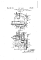
- Fig. 3 is a v1ew in side elevation ofthe device, a small portion thereofbeing shown in vertical section;
- I y f Fig. 4 is a horizontal section takenonthe line 4:& of Fig. 2,as indicated by'the arrows;
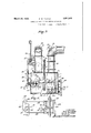
- Fig. 5 is a vertical section taken on the line 55 of Fig. 1, as indicatedby the arrows, portions of the top of the container being omitted;
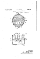
- Fig.6 is a ating means for the valve, said view being in elevation, a portion thereof being shown in vertical section.
- the device comtainer may be 'of-various shapes, in the embodim'ent of. the invention illustrated, the samelis shown as substantially cylindrical in horizontal crosssectionsand having acomdiagrammatic view of theoper- 7 paratively flat top andbottom. portions 1a and 1b.
- the top portion is provided with a man hole 10 through which accessmaybe had to the interior of the device, which man hole will, of course, be provided with a suitable covering not'sh'own.
- the container 1 is also provided at spaced circumferential points thereabout, with openings in the peripheral wall. These openings are equipped with and closed by doors 2, one of said openings being adjacent the bottom of the device, and the others being adjacent the center thereof.
- the said openings have apertured plates 3 extending thereabout from which project the pintle lugs 3a carrying the. pintle 1 on which the doors 2 are hinged by their lugs 2a.
- the plates 3 also have rising therefrom adjacent their central portions, and at one edge thereof, the lugs 36 between which is pivotally mounted a yoke 5 adapted to extend horizontally across the door 2 substantially centrally thereof, and the free end of which is adapted tobe received in a yoke 6 hinged to plate 3.
- the yoke 5 has a hub 5a at its central portion threadedto receive a screw 7 having a cross handle 7a at its outer end.
- the screw 7, at its inner end is adapted to bear against the door 2.
- inlet conduits 8 and '95 Extending down into the container 1 through the top thereof are the inlet conduits 8 and '95 which "are illustrated as having a flange 8a extending thereabout and between the same resting upon the top 1a of the container 1.
- Conduits 10 and 11 are connected, respectively, to the: flange 8a and communicate, respectively, with the conduits 8 and 9.
- Co-operating with the lower open ends of the conduits 8 and 9 arevalves in the form of plates 12 and 13 having the upwardly extending flanges 12a and 13a at their outer edges.
- lever 15 has two oppositely extending arms having upturned ends carrying the balls in: and said lever has a central arm projecting upwardly therefrom formed with a hub secured to a shaft 17, which shaft is journaled in a bearing 18 secured between the conduits 8 and 9 and in a stufiingbox 19 secured at the outer side of container 1.
- the rod 2.1 extends beyond the pisten 24 and through the cylinder head
- the cylinder 22 is supported from the side of container 1 by a bracket 25 which will be riveted or bolted to said container.
- the lever 20 has pivotally connected thereto at or adj acent its outer free end, the forked lower end of a rod 26 which extends upwardly and has its forked upper end connected to the outer end of an arm 27.
- the arm 27 is connected to the movable part of a three-way valve indicated at 28 and disposed in a conduit 29 having branches 29a and 296 leading respectively into conduits 10 and 11.
- a conduit 30 communicates with an opening. in the top 164 of the container, and extends upwardly and laterally therefrom.
- conduits 10, 11 and 30 are illustrated as provided with man holes equipped with covers 31 and clamping handles 32 therefor. It will be noted that conduits 10 and 11 are adjacent one side of the container while the conduit 30 is adjacent the opposite side thereof.
- A. perforated partition 33 extends across the interior of container 1 slightly abovethe lowerends. of conduitsS and 9 and said partition is inclined upwardly toward the side on which the conduit 30 is located.
- the said partition 33 is formed of a plurality of perforated plates 3 i which are slightly spaced at their edges and. are supported on means secured to the inner wall of. the container 1.
- Container 1 isadapted to contain a liquid such as water, the level of which will be maintained just above the upper edge. of the partition 33, as indicated by thedotted line 37 in Figs. 8' and 5,. and it will be noted that the ends of conduits 8 and 9 extend some distance below this water level, and that these conduits also extend downwardly through the partition
- An overflow pipe 38 communicates with the container 1 just above the upper edge of partition 33 to maintain the water level as described, which pipe is equipped with a valve 39.
- a drain pipe 40 is'shown as communicating with the lower portion of overflow pipe 38 and pipe. 40 is also equipped with a valve 4.1.
- a filling pipe 12 communicates with the container 1 at some distance above its bottom which pipe extends upward above the container and is shown as having a cup reservoir 13 at its upper end.
- the piston 24 in cylinder. 23 is adapted to be operated by steam pipes is and 4.5 which are communicating, respectively, with ports at the opposite ends of said cylinder 23.
- the pipe 44 communicates with one opening or side of a four-way valve 46 and a pipe 45 communicates with one side or opening of a four-way valve d7, similarly disposed openings on said valves being connected by a pipe 18.
- a steam supply pipe 50 connects with one side of valve 45 and an exhaust steam pipe i9 connects with the opposite side of valve 46 and with the side of valve 17 opposite that to which pipe a8 is connected.
- the cylinder 23 is provided with ports 23?) and 230 disposed at each side of its longitudinal center and a sufiicient distance apart to just be covered by the edges of piston 24.
- a pipe 51 communicates with port 236 and with the side of valve47 opposite that to which pipe 45 is connected and saidlpipe 51 has a branch 52 communicating with the port 230.
- Check valves 53 are provided in pipes 51 and 52 so arranged as to permit passage of steam out of the cylinder but to prevent passage of steam into the cylinder therethrough.
- the gas from. the gas making apparatus will come throughone or the other of the conduits 10 or 11 and will be discharged into the seal-through one ofthe conduits 8 or 9.
- the valves 12 and 13 are'operated through the lever 15 and by the steam piston '24.
- the piston. 24 is at one end of the cylinder 23.
- steam will be admitted from any suitable control means through the pipe 50.
- Valve 46 will be so turnedthat this steam passes therethrough into pipe 44' and .3 into the upper end of cylinder 23;
- the valve 47 willbe so turned that pipe45 will communicate with pipe 48 and through valve 46 with exhaust pipe 49.
- the live steam entering the cylinder 23 will therefore force piston 24 down and lever 20 will be swung to move valve 12 to its closed position. If it be clesired to open valve 12 and close conduit 9 by valve 13, the live steam will be admitted to pipe 50, valve 47 willbe so turned as to connectpipes 50 and 45 and valve 46 will be turned to connect pipes 44 and 49 so that the live steam will be delivered to the cylinder 23 below piston 24. Pipe 44 will then be connected to exhaust pipe 49 so that the steam above the piston 24 will be exhausted through said exhaust pipe. The piston 24 will then be forced upwardly and valve leverv 15 swung to open valve 12 and move valve 13yto closed position.
- the control valves l2;-and 13 are conven iently arranged and constructed for efiicient action.
- the universal'joint by which the valves are connected to the lever-15 allow the plates to seat perfectly on the ends of condu1ts'8 and 9.
- there ISELlWELYS an accumulation of carbon and hydrocar'bon products, such as tar, which causes difliculty in operating valves .of the ordinary type, such as sliding gate valves. 1
- the valves 12 and 13. it-will be noted,pull directly away from their seats which are formed by the edges of the conduits 8 and 9, so that there is very little friction or tendencyto stick and retard the operation of the valve.
- the lever 15 is quickly operated and the valve plates 12 and ing of the valve obtained.
- the seal is conveniently arranged for the accommodationoftwo inlet pipes so that one seal can be used with a double gas making set.
- the valve operating mechanism is also conveniently connected to the steam control valve. The entire apparatus is compact, efficient inoperation and convenient and easily constructed. The apparatus has been thoroughly demonstrated in actual practice and found to be very suc cessful.
- a hydraulic seal and washer for gas having. in combination, a closed container adapted to contain a body of "liquid to a certain depth therein, two gas inlet conduits extending into said container below the level of liquid therein, and disposed at one side of 'i said container, a discharge conduit connected to the top of said container at the opposite side thereof, a partition in said container comprising slightly spaced narrow perforated plates extending across said container and inclining upwardly away from said inlet conduits and disposed beneath the level of said liquid and above the lower ends of said inlet conduits, and means secured to said container on which said plates rest whereby gas issuing from said inlet conduits will pass up and along and beneath said partition and be successively divided into small portions.
- a hydraulic seal for gas having in combination, a closed container adapted to contain liquid, tWo gas inlet conduits extending into said container and below the level of liquid therein and disposed at one side of said container, a discharge conduit connected to the top of said container at the opposite side thereof, a perforated partition surrounding said inlet conduits extending across said container in an upwardly inclined direction and being disposed a short distance above the lower end of said first mentioned conduit and below the level of liquid in said container, an outlet pipe communicating with said container just above the upper end of said partition forming an overflow device and a drain outlet at the bottom of said container.
- a device of the class described having in combination, a container adapted to contain liquid, an inlet conduit for gas extending into said container and having its outlet end below the levelof the liquid therein, a discharge conduit connected to the top of said container and a perforated partition eX- tending across said container in an'upwardly inclined direction a short distance above the discharge end of said inlet conduit and below the level of the: liquid in said container, whereby the gas'issuing from said inlet conduit would pass along the under side of said partition and be broken up thereby.
- a hydraulic seal for gas having in combination, a closed container adapted to contain' a quantity of liquid therein, two conduits extending into said container and having open lower ends disposed below the level of liquid therein, an oscillating valve in said container carrying two plates oscillatably mounted and adapted to co-operate respectively with the ends of said conduits to open and close thesame or to be held in an intermediateposition with both conduits open, an operating member for said valve comprising a piston, a cylinder in which said piston is movable, means for delivering steam at the end portion of said cylinder and at intermediate portions therein, and controlling means for said steam to admit steam to different portions of said cylinder to move said valves alternately to close one conduit and open the other, or to hold said valves in position with both conduits open.
Landscapes
- Chemical & Material Sciences (AREA)
- Engineering & Computer Science (AREA)
- Oil, Petroleum & Natural Gas (AREA)
- Chemical Kinetics & Catalysis (AREA)
- General Chemical & Material Sciences (AREA)
- Materials Engineering (AREA)
- Organic Chemistry (AREA)
- Pipeline Systems (AREA)
Description
March 29, 1932. p, w THAYER 1,851,069
HYDRAULIC SEAL FOR GAS MAKING APPARATUS Filed April 7 1924 3 Sheets-Sheet 1 March 2 1932. P, w, THAYER 1,851,069
HYDRAULIC SEAL FOR GAS MAKING APPARATUS Filed A ril'v, 1924 s Sheets-Sheet 2 Fry. 5.
March 29, 1932. P. w. THAYER HYDRAULIC SEAL FOR GAS MAKING APPARATUS Filed pril47 1924 5 Sheets-Sheet 3 PA UL W THA YE")? 25 Y /7/J ATTOFNE) I I l Patented Mar. 29, 1932 nrarrzsgarss PAUL w. T'HAYER, or MINNEAPOLIS, INNESOTA, AssIGrIon To AMERICAN (Bassoon srnuorron ooivrr mr, on ivnwroiv, IowA, A CORPORATION or rowA nvnnAn'rro. SEAL Fora ass M KING APPARATUS Application filed. Apri1 7 1924'. Serial at. 704,872.
This invention relates to a hydraulic seal, such asused in connection with gas making apparatus. The gas from the generating apparatus is passed through the seal so that the liquid seal is disposed between said apparatus and'the washing and storing apparatus for the gas. The seal of the present invention is also adapted to break up the gas passing thereinto and to thus have a washing or to scrubbing efiect thereon. It is a more or less common practice in gas making to. have a plurality of conduits through which the generated gas is discharged from the gas making apparatus, and in general, onlyfoneof is these conduits is used for the passage of gas at one time.
It is an object of this invention to provide a hydraulic seal adapted to receive a'plu-' rality of gas discharging conduits, the ends of said conduits being open and extending below the level of the liquid maintained in said seal, and having a valve mechanismtherein adapted alternately toopen "and close said conduits. F v v p 1 Z5 Itis a further object of this invention to have such a seal and valve, which valve is oscillatable and carries a plurality of-platelike valves, preferably mounted on universal joints to cooperate With the ends of'said conduits. i
crate such a valve by'means connected to the piston of a steam cylinder, which cylinder and means are disposed outside of the seal. 7 35 It is a further object of the invention to provide a hydraulic seal comprising a closed 1 prises a closedcontainer 1.. Wh1le th s concontainer into the top of which and at one side thereof, a pluralityof-conduits extend through which the gas passes into the seal extends upwardly toward the side of the container from which the last mentioned conduit leads. 1 1 f It is a further object of the invention to 59 form this perforated plate of'spaced elongat It is a further object of the'invention to op and from the top of which and adjacentthe.
ed sections supported on means secured to the inner side of the container.; I
It is alsoan object of. the. invention to pro-. vide such a container with suitableoverflow anddrain means and with various openings for cleaning'purposes. I
It is-still another'objectof the inventionto provide mechanism for moving .the above mentioned valve and holding thesame in va- 'riouspositionsa '1' 1 I These and other objects'and advantages of the invention will be fully .set forth in the following description made in connection with the accompanying drawings in which like reference characters refer tothe same parts throughout the difl'erent views, and in which Fig. 2 is a view in frontelevation'of .the
device Fig. 3 is a v1ew in side elevation ofthe device, a small portion thereofbeing shown in vertical section; I y f Fig. 4 is a horizontal section takenonthe line 4:& of Fig. 2,as indicated by'the arrows; Fig. 5 is a vertical section taken on the line 55 of Fig. 1, as indicatedby the arrows, portions of the top of the container being omitted; and Fig.6 is a ating means for the valve, said view being in elevation, a portion thereof being shown in vertical section.
Referring-tothe drawings, the device comtainer may be 'of-various shapes, in the embodim'ent of. the invention illustrated, the samelis shown as substantially cylindrical in horizontal crosssectionsand having acomdiagrammatic view of theoper- 7 paratively flat top andbottom. portions 1a and 1b. The top portion is provided with a man hole 10 through which accessmaybe had to the interior of the device, which man hole will, of course, be provided with a suitable covering not'sh'own. The container 1 is also provided at spaced circumferential points thereabout, with openings in the peripheral wall. These openings are equipped with and closed by doors 2, one of said openings being adjacent the bottom of the device, and the others being adjacent the center thereof. The said openings have apertured plates 3 extending thereabout from which project the pintle lugs 3a carrying the. pintle 1 on which the doors 2 are hinged by their lugs 2a. The plates 3 also have rising therefrom adjacent their central portions, and at one edge thereof, the lugs 36 between which is pivotally mounted a yoke 5 adapted to extend horizontally across the door 2 substantially centrally thereof, and the free end of which is adapted tobe received in a yoke 6 hinged to plate 3. The yoke 5 has a hub 5a at its central portion threadedto receive a screw 7 having a cross handle 7a at its outer end. The screw 7, at its inner end, is adapted to bear against the door 2. The above description applies to all ofithe doors 2'illustrated.
Extending down into the container 1 through the top thereof are the inlet conduits 8 and '95 which "are illustrated as having a flange 8a extending thereabout and between the same resting upon the top 1a of the container 1. Conduits 10 and 11 are connected, respectively, to the: flange 8a and communicate, respectively, with the conduits 8 and 9. Co-operating with the lower open ends of the conduits 8 and 9 arevalves in the form of plates 12 and 13 having the upwardly extending flanges 12a and 13a at their outer edges. Said platesare formed with upwardly extending substantially conical central portions 12?), 13?) which are hollow to receive the rounded ball-like ends 15a of a lever 15, said plates being held on the ends of said lever by attaching plates 16 secured to plates 12 and 13 by a plurality of headed and nutted boltsthus forming universal joints between lever 15 and plates 12 and 13. As clearly shown in Fig. 5, lever 15 has two oppositely extending arms having upturned ends carrying the balls in: and said lever has a central arm projecting upwardly therefrom formed with a hub secured to a shaft 17, which shaft is journaled in a bearing 18 secured between the conduits 8 and 9 and in a stufiingbox 19 secured at the outer side of container 1. To the outer end of said shaft is connected a hub formed at oneend of a lever 20, which lever extends substantially horizontally at one side of the container land has pivotally connected theretointermediate its ends, the lower end of a connecting rod 21 which extends into a steam cylinder 22 and is connected to the piston 24 therein. The rod 2.1 extends beyond the pisten 24 and through the cylinder head The cylinder 22 is supported from the side of container 1 by a bracket 25 which will be riveted or bolted to said container. The lever 20 has pivotally connected thereto at or adj acent its outer free end, the forked lower end of a rod 26 which extends upwardly and has its forked upper end connected to the outer end of an arm 27. The arm 27 is connected to the movable part of a three-way valve indicated at 28 and disposed in a conduit 29 having branches 29a and 296 leading respectively into conduits 10 and 11.
A conduit 30 communicates with an opening. in the top 164 of the container, and extends upwardly and laterally therefrom.
The conduits 10, 11 and 30 are illustrated as provided with man holes equipped with covers 31 and clamping handles 32 therefor. It will be noted that conduits 10 and 11 are adjacent one side of the container while the conduit 30 is adjacent the opposite side thereof. A. perforated partition 33 extends across the interior of container 1 slightly abovethe lowerends. of conduitsS and 9 and said partition is inclined upwardly toward the side on which the conduit 30 is located. The said partition 33 is formed of a plurality of perforated plates 3 i which are slightly spaced at their edges and. are supported on means secured to the inner wall of. the container 1. While any suitable supporting means mi ht be provided for the plates 34-, in the embodiment of the invention illustrated, said supporting; means is shown as comprising a substantially circular rod 35 passing through suitable angle brackets 36 bolted or riveted to the wall of container 1. Container 1 isadapted to contain a liquid such as water, the level of which will be maintained just above the upper edge. of the partition 33, as indicated by thedotted line 37 in Figs. 8' and 5,. and it will be noted that the ends of conduits 8 and 9 extend some distance below this water level, and that these conduits also extend downwardly through the partition An overflow pipe 38 communicates with the container 1 just above the upper edge of partition 33 to maintain the water level as described, which pipe is equipped with a valve 39. A drain pipe 40 is'shown as communicating with the lower portion of overflow pipe 38 and pipe. 40 is also equipped with a valve 4.1. A filling pipe 12 communicates with the container 1 at some distance above its bottom which pipe extends upward above the container and is shown as having a cup reservoir 13 at its upper end. The piston 24 in cylinder. 23 is adapted to be operated by steam pipes is and 4.5 which are communicating, respectively, with ports at the opposite ends of said cylinder 23. The pipe 44 communicates with one opening or side of a four-way valve 46 and a pipe 45 communicates with one side or opening of a four-way valve d7, similarly disposed openings on said valves being connected by a pipe 18. A steam supply pipe 50 connects with one side of valve 45 and an exhaust steam pipe i9 connects with the opposite side of valve 46 and with the side of valve 17 opposite that to which pipe a8 is connected. v The cylinder 23 is provided with ports 23?) and 230 disposed at each side of its longitudinal center and a sufiicient distance apart to just be covered by the edges of piston 24. A pipe 51 communicates with port 236 and with the side of valve47 opposite that to which pipe 45 is connected and saidlpipe 51 has a branch 52 communicating with the port 230. Check valves 53 are provided in pipes 51 and 52 so arranged as to permit passage of steam out of the cylinder but to prevent passage of steam into the cylinder therethrough.
In operation, the gas from. the gas making apparatus will come throughone or the other of the conduits 10 or 11 and will be discharged into the seal-through one ofthe conduits 8 or 9. The valves 12 and 13 are'operated through the lever 15 and by the steam piston '24. When the plate valves 12 and. 13 are inan entirely opened or closed position, the piston. 24 is at one end of the cylinder 23. If it be desired to close conduit 8by valve 12, as shown in Fig. 5, steam will be admitted from any suitable control means through the pipe 50. Valve 46 will be so turnedthat this steam passes therethrough into pipe 44' and .3 into the upper end of cylinder 23; The valve 47 willbe so turned that pipe45 will communicate with pipe 48 and through valve 46 with exhaust pipe 49. The live steam entering the cylinder 23 will therefore force piston 24 down and lever 20 will be swung to move valve 12 to its closed position. If it be clesired to open valve 12 and close conduit 9 by valve 13, the live steam will be admitted to pipe 50, valve 47 willbe so turned as to connectpipes 50 and 45 and valve 46 will be turned to connect pipes 44 and 49 so that the live steam will be delivered to the cylinder 23 below piston 24. Pipe 44 will then be connected to exhaust pipe 49 so that the steam above the piston 24 will be exhausted through said exhaust pipe. The piston 24 will then be forced upwardly and valve leverv 15 swung to open valve 12 and move valve 13yto closed position. It is sometimes desirableto have both conduits 8 and 9 open; For this purpose, live steam is supplied as usual to pipe 50 and valves 46 and 47 are set as shown in Fig. 6. Live steam is thus turned into the pipes 44 and 45 at each end of the cylinder 23. Pipe 51, as well as pipe 22 are connected-to the exhaust pipe 49 through the valves 47 and 46 and pipe 48. If the piston 24 is in central position so as to cover the ports 23c and 2312, the live steam pressure will balance at each side of piston 24 and said piston will remain in its central position. Should said piston move downward, to uncover the upper port 23?), steam will be exhausted through the valve 53 and pipe 51 so that the pressure will be greater on the lower side of the piston. Said piston will then be moved upwardly to close said port 235. If the piston should move upwardly so as to uncover the port 230, the pressure would become greater on the top of the piston and the same will :beforced tion 33 and portions thereof will escape through the holes in saidplates and through the cracks between the plates. The gas bubbles will be sliced up, as'it were, and thus be broken up so than an efficient washing efi'ect will be produced. The gas eventually all rises throughpartition 33 and passes out ofthe'seal through the conduit 30 to the proper cleaning and storing apparatus. i With the type of apparatus disclosed, in
certain parts of the gas making. operations,
steam is run into the conduits '10 and llzin a directionaway from the seal" or container 1". Thesteam will pass into-the conduit ;1'0.when the valve 12 is closed and -'into-theconduit 11 when the valve 13 is closed. This. steam is passed into said conduits through the pipe or conduit 29 and the valve 28' is properly po sitioned to turn the steam'into the proper conduit when the valves l2'and 13 are operated. This automatic operation of. valve28 takes place through the rod 26 connectedto lever 20.
T he container 1 is supplied with water through the pipe 42 and the proper level of water. therein ismaintained by the overflow pipe 38, the valve 39 therefore normally beif ing open. When it isdesiredto drainthe container, the valve 41 is opened and the water drains out through. pipe 40. The con-. tainer can then be cleaned by having access thereto through the doors 2' or'the man. hole From the above description it is seen that applicant has provided a simple and efiicient V hydraulicseal for a gas making apparatus:
The control valves l2;-and 13 are conven iently arranged and constructed for efiicient action. The universal'joint by which the valves are connected to the lever-15 allow the plates to seat perfectly on the ends of condu1ts'8 and 9. With such apparatus, there ISELlWELYS an accumulation of carbon and hydrocar'bon products, such as tar, which causes difliculty in operating valves .of the ordinary type, such as sliding gate valves. 1 The valves 12 and 13. it-will be noted,pull directly away from their seats which are formed by the edges of the conduits 8 and 9, so that there is very little friction or tendencyto stick and retard the operation of the valve. Bypro viding the steam operation, the lever 15 is quickly operated and the valve plates 12 and ing of the valve obtained.
13 are slapped, as it were, against the. ends of conduits 8 and 9 so that any deposit on the valve seats is apt to be expelled to one side or the other thereof and a perfect clos- The gas passing into the seal is efiiciently broken up and large bubbles of gas cannot pass through with the accompanying dangers. The seal is conveniently arranged for the accommodationoftwo inlet pipes so that one seal can be used with a double gas making set. The valve operating mechanism is also conveniently connected to the steam control valve. The entire apparatus is compact, efficient inoperation and convenient and easily constructed. The apparatus has been thoroughly demonstrated in actual practice and found to be very suc cessful.
It will, of course, be understood, that various changes may be made in the form, de-
tails, arrangement and proportion of the parts without departing from the scope of applicants. invention, which, generally stated, consists in a device capable-of carrying out the objects above set forth, such as shown and described and defined in the appended claims.
lVhat is claimed is:
1. A hydraulic seal and washer for gas having. in combination, a closed container adapted to contain a body of "liquid to a certain depth therein, two gas inlet conduits extending into said container below the level of liquid therein, and disposed at one side of 'i said container, a discharge conduit connected to the top of said container at the opposite side thereof, a partition in said container comprising slightly spaced narrow perforated plates extending across said container and inclining upwardly away from said inlet conduits and disposed beneath the level of said liquid and above the lower ends of said inlet conduits, and means secured to said container on which said plates rest whereby gas issuing from said inlet conduits will pass up and along and beneath said partition and be successively divided into small portions.
2. A hydraulic seal for gas having in combination, a closed container adapted to contain liquid, tWo gas inlet conduits extending into said container and below the level of liquid therein and disposed at one side of said container, a discharge conduit connected to the top of said container at the opposite side thereof, a perforated partition surrounding said inlet conduits extending across said container in an upwardly inclined direction and being disposed a short distance above the lower end of said first mentioned conduit and below the level of liquid in said container, an outlet pipe communicating with said container just above the upper end of said partition forming an overflow device and a drain outlet at the bottom of said container.
3. A device of the class described having in combination, a container adapted to contain liquid, an inlet conduit for gas extending into said container and having its outlet end below the levelof the liquid therein, a discharge conduit connected to the top of said container and a perforated partition eX- tending across said container in an'upwardly inclined direction a short distance above the discharge end of said inlet conduit and below the level of the: liquid in said container, whereby the gas'issuing from said inlet conduit would pass along the under side of said partition and be broken up thereby.
.4. A hydraulic seal for gas having in combination, a closed container adapted to contain' a quantity of liquid therein, two conduits extending into said container and having open lower ends disposed below the level of liquid therein, an oscillating valve in said container carrying two plates oscillatably mounted and adapted to co-operate respectively with the ends of said conduits to open and close thesame or to be held in an intermediateposition with both conduits open, an operating member for said valve comprising a piston, a cylinder in which said piston is movable, means for delivering steam at the end portion of said cylinder and at intermediate portions therein, and controlling means for said steam to admit steam to different portions of said cylinder to move said valves alternately to close one conduit and open the other, or to hold said valves in position with both conduits open.
In testimony whereof I aflix my signature.
PAUL W. THAYER.
Priority Applications (1)
| Application Number | Priority Date | Filing Date | Title |
|---|---|---|---|
| US704872A US1851069A (en) | 1924-04-07 | 1924-04-07 | Hydraulic seal for gas making apparatus |
Applications Claiming Priority (1)
| Application Number | Priority Date | Filing Date | Title |
|---|---|---|---|
| US704872A US1851069A (en) | 1924-04-07 | 1924-04-07 | Hydraulic seal for gas making apparatus |
Publications (1)
| Publication Number | Publication Date |
|---|---|
| US1851069A true US1851069A (en) | 1932-03-29 |
Family
ID=24831188
Family Applications (1)
| Application Number | Title | Priority Date | Filing Date |
|---|---|---|---|
| US704872A Expired - Lifetime US1851069A (en) | 1924-04-07 | 1924-04-07 | Hydraulic seal for gas making apparatus |
Country Status (1)
| Country | Link |
|---|---|
| US (1) | US1851069A (en) |
Cited By (1)
| Publication number | Priority date | Publication date | Assignee | Title |
|---|---|---|---|---|
| US2429721A (en) * | 1944-01-28 | 1947-10-28 | Standard Oil Dev Co | Contacting gases and solids in fluidized systems |
-
1924
- 1924-04-07 US US704872A patent/US1851069A/en not_active Expired - Lifetime
Cited By (1)
| Publication number | Priority date | Publication date | Assignee | Title |
|---|---|---|---|---|
| US2429721A (en) * | 1944-01-28 | 1947-10-28 | Standard Oil Dev Co | Contacting gases and solids in fluidized systems |
Similar Documents
| Publication | Publication Date | Title |
|---|---|---|
| US1851069A (en) | Hydraulic seal for gas making apparatus | |
| US1596997A (en) | Drip pan | |
| US695330A (en) | Hominy huller and washer. | |
| US1538210A (en) | Apparatus for cooking and pressing | |
| US1693612A (en) | Manufacture of livestock feeds | |
| US1792769A (en) | Feather drier | |
| US560808A (en) | Rotary cooker | |
| US1198974A (en) | Can-washing apparatus. | |
| US1801687A (en) | Vacuum head and deodorizer | |
| US1459629A (en) | Heating apparatus for leaches | |
| US260266A (en) | Robert whelan | |
| US606396A (en) | Cask-pitching apparatus | |
| US1374291A (en) | Mixing-tank | |
| US108000A (en) | Improvement in feather-renovators | |
| US127995A (en) | Improvement in apparatus for boiling bones, refuse meats | |
| US1604455A (en) | Can washing, sterlilizing, and drying apparatus | |
| US1737115A (en) | Cleaning machine | |
| US1550668A (en) | Valve for milk-pasteurizer tanks | |
| US494463A (en) | Machine for scalding tomatoes | |
| US1261895A (en) | Waste-valve. | |
| US506752A (en) | Evaporating-pan | |
| US1580502A (en) | Mechanism for automatic turning of irrigating pipes | |
| US1620116A (en) | Can washer | |
| US287292A (en) | Cooking-steamer | |
| US1021763A (en) | Closet. |