US1851059A - Automatic gear shifting mechanism - Google Patents
Automatic gear shifting mechanism Download PDFInfo
- Publication number
- US1851059A US1851059A US502678A US50267830A US1851059A US 1851059 A US1851059 A US 1851059A US 502678 A US502678 A US 502678A US 50267830 A US50267830 A US 50267830A US 1851059 A US1851059 A US 1851059A
- Authority
- US
- United States
- Prior art keywords
- head
- shifting
- arm
- shaft
- movement
- Prior art date
- Legal status (The legal status is an assumption and is not a legal conclusion. Google has not performed a legal analysis and makes no representation as to the accuracy of the status listed.)
- Expired - Lifetime
Links
- 230000007246 mechanism Effects 0.000 title description 39
- 230000033001 locomotion Effects 0.000 description 22
- 230000005540 biological transmission Effects 0.000 description 17
- 230000007935 neutral effect Effects 0.000 description 3
- 230000000994 depressogenic effect Effects 0.000 description 2
- 230000000694 effects Effects 0.000 description 2
- 230000002093 peripheral effect Effects 0.000 description 2
- 102000003800 Selectins Human genes 0.000 description 1
- 108090000184 Selectins Proteins 0.000 description 1
- 210000003414 extremity Anatomy 0.000 description 1
- 210000003141 lower extremity Anatomy 0.000 description 1
- 238000003754 machining Methods 0.000 description 1
- AAEVYOVXGOFMJO-UHFFFAOYSA-N prometryn Chemical compound CSC1=NC(NC(C)C)=NC(NC(C)C)=N1 AAEVYOVXGOFMJO-UHFFFAOYSA-N 0.000 description 1
- 239000011435 rock Substances 0.000 description 1
Images

Classifications
-
- F—MECHANICAL ENGINEERING; LIGHTING; HEATING; WEAPONS; BLASTING
- F16—ENGINEERING ELEMENTS AND UNITS; GENERAL MEASURES FOR PRODUCING AND MAINTAINING EFFECTIVE FUNCTIONING OF MACHINES OR INSTALLATIONS; THERMAL INSULATION IN GENERAL
- F16H—GEARING
- F16H63/00—Control outputs from the control unit to change-speed- or reversing-gearings for conveying rotary motion or to other devices than the final output mechanism
- F16H63/40—Control outputs from the control unit to change-speed- or reversing-gearings for conveying rotary motion or to other devices than the final output mechanism comprising signals other than signals for actuating the final output mechanisms
- F16H63/46—Signals to a clutch outside the gearbox
-
- B—PERFORMING OPERATIONS; TRANSPORTING
- B60—VEHICLES IN GENERAL
- B60W—CONJOINT CONTROL OF VEHICLE SUB-UNITS OF DIFFERENT TYPE OR DIFFERENT FUNCTION; CONTROL SYSTEMS SPECIALLY ADAPTED FOR HYBRID VEHICLES; ROAD VEHICLE DRIVE CONTROL SYSTEMS FOR PURPOSES NOT RELATED TO THE CONTROL OF A PARTICULAR SUB-UNIT
- B60W10/00—Conjoint control of vehicle sub-units of different type or different function
- B60W10/02—Conjoint control of vehicle sub-units of different type or different function including control of driveline clutches
-
- B—PERFORMING OPERATIONS; TRANSPORTING
- B60—VEHICLES IN GENERAL
- B60W—CONJOINT CONTROL OF VEHICLE SUB-UNITS OF DIFFERENT TYPE OR DIFFERENT FUNCTION; CONTROL SYSTEMS SPECIALLY ADAPTED FOR HYBRID VEHICLES; ROAD VEHICLE DRIVE CONTROL SYSTEMS FOR PURPOSES NOT RELATED TO THE CONTROL OF A PARTICULAR SUB-UNIT
- B60W10/00—Conjoint control of vehicle sub-units of different type or different function
- B60W10/10—Conjoint control of vehicle sub-units of different type or different function including control of change-speed gearings
-
- B—PERFORMING OPERATIONS; TRANSPORTING
- B60—VEHICLES IN GENERAL
- B60K—ARRANGEMENT OR MOUNTING OF PROPULSION UNITS OR OF TRANSMISSIONS IN VEHICLES; ARRANGEMENT OR MOUNTING OF PLURAL DIVERSE PRIME-MOVERS IN VEHICLES; AUXILIARY DRIVES FOR VEHICLES; INSTRUMENTATION OR DASHBOARDS FOR VEHICLES; ARRANGEMENTS IN CONNECTION WITH COOLING, AIR INTAKE, GAS EXHAUST OR FUEL SUPPLY OF PROPULSION UNITS IN VEHICLES
- B60K2702/00—Control devices wherein the control is combined with or essentially influenced by the engine or coupling, e.g. in an internal combustion engine, the control device is coupled with a carburettor control device or influenced by carburettor depression
- B60K2702/08—Semi-automatic or non-automatic transmission with toothed gearing
- B60K2702/18—Semi-automatic or non-automatic transmission with toothed gearing with a preselection system, e.g. semi-automatic
- B60K2702/20—Semi-automatic or non-automatic transmission with toothed gearing with a preselection system, e.g. semi-automatic using different control members for preselection and actuating, e.g. shift actuation is initiated by clutch pedal with elastic connection for energy accumulation
-
- Y—GENERAL TAGGING OF NEW TECHNOLOGICAL DEVELOPMENTS; GENERAL TAGGING OF CROSS-SECTIONAL TECHNOLOGIES SPANNING OVER SEVERAL SECTIONS OF THE IPC; TECHNICAL SUBJECTS COVERED BY FORMER USPC CROSS-REFERENCE ART COLLECTIONS [XRACs] AND DIGESTS
- Y10—TECHNICAL SUBJECTS COVERED BY FORMER USPC
- Y10T—TECHNICAL SUBJECTS COVERED BY FORMER US CLASSIFICATION
- Y10T74/00—Machine element or mechanism
- Y10T74/19—Gearing
- Y10T74/19219—Interchangeably locked
- Y10T74/19242—Combined gear and clutch
- Y10T74/19247—Preselector
Definitions
- the invention embodies an improved mechanism by means of which the gears of a vehicle transmission are selected and shifted,
- An object of. the invention is to provide a device of theabove character, wherein a manual selective mechanism is provided for effecting a predetermined gear shifting operation and means is further provided, actuated by the clutch mechanism of the vehicle, to perfect the shifting operation.
- the shiftingmemberofthemechanism be movable as a unit and associated with cooperating mechanism in such fashion as to prevent more than one shifting operation to take place at the sametinie, andfurther prevent the perfection of a shifting operation until a pre-. viously engaged set of gears has been disengaged to clear the mechanism for the proposed shift.
- a further object of the invention is to provide a device of the above character, wherein an extremely accurate selective mechanism is provided, the machined elements thereof being reduced to a minimum without destroyingthc accuracy of the mechanism.
- a further object of the invention is to provide a locking mechanism to prevent an incorrect engagement of the elements of the shifting mechanism and thus eliminate any i danger of an imperfect shift.
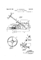
- Figure 1 is a perspective view of a portion of a' vehicle chassis upon which a device constructed in accordance with the present invention has been installed.
- Figure 2 is' a plan View, taken on line22 of Figure 2, showing the selective mechanism embodied upon the steering wheel of a motor vehicle chassis.
- Figure 3 is a view in section, taken on line 3-3 of Figure 1, and showing the manner of transmitting the motion or theselective mechanism to the shifting mechanism mounted upon the transmission.
- Figure e is a .view taken on line 4-4 of Figure 1, showing the manner in'which the shifting actuation is derived from the clutch actuating mechanism.
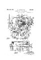
- Figure 5 is a plan 'view of the shifting mechanism of the present invention.
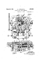
- Figure 6 is a view in section, taken on line 6-6 of F igure5, and looking in the direction of the arrows.
- Figure 7 is a view in section, taken on line 7-7 of Figure 5 and looking in the direction of thearrows.
- Figure 8 is a view similar to Figure 7,
- the chassis of a motor vehicle is indicated at 10 "and is provided with an engine 11 and transmission shaft 12.
- a clutch bell housing is shown at 13 and carries a transmission housing 14 of standard design.
- the standard 5 clutch pedal is shown at 15 and the steering column at 16, the latter being provided with a steering wheel 17 upon which a selecting arm 18 is mounted.
- the selecting arm is carried by a shaft within the steering column" l6 and is connected at its lower end, to an arm 19 which carries a link 20 for transmitting movement of the arm to hell crank lever 21.
- the other arm of bell crank lever 21 is connected to an arm 22 of the shifting mechanism described hereinafter by means of a link 23.
- a housing 24 is secured, this housing being provided with a lid 25 and journaling a shaft 26.
- Crank arm 27 is carried by the shaft 26 and is connected to the clutch release shaft 28 by means of a lever 29 and link .30. WVhen the clutch pedal 15 is actuated the shaft 26 is turned and perfects the shifting operations as described hereinafter.
- the transmission mechanism is provided with two shifter shafts 30 and 31 upon which are mounted the shifter forks 32 for engaging the respective gear sets of the transmission mechanism. These forks are mounted upon sleeves 33 which are carried by the shafts 30 and 31. Mounted transversely within the housing 24 is a shaft 34 upon which arms 35 are j ournaled. The lower extremities of arms 35 are connected to the respective sleeves 33 by means of links 36 and movement of the sleeves is effected by means of devices for actuating the arms 35 as described hereinafter.
- a shaft 26 is provided with a squared section and slidably carries a sleeve 40 having V a head 41.
- This head is provided with a plurality of rollers 42, the axes of which lie in a common plane and spaced upon opposite sides of the shaft 26.
- the rollers are ofiset laterally and the head is provided with recesses 43 upon opposite sides thereof, and aligned with the respective rollers.
- a guide plate 44 is mounted being pivoted at 45.
- the guide plate is formed with an outwardly extending arm 22 which is connected to the link 23 and the other extremity of the arm forms a head within which a guide groove or slot 47 is formed.
- a notched lock plate 48 is carried by the guide plate and a detent 49 normally engages the notches of the plate 48 under pressure of spring 50 to maintain the guide plate in any position to which it has been moved.
- An arm 51 is pivoted at 52 in one wall of the housing and is provided with a roller 53 which engages the slot 47.
- the arm is formed with an offset portion 54 and carries a pin or roller 55 which is adapted to engage a groove 56 in the sleeve 40, as described more particularly hereinafter. It is desired that the free end of arm 51 be received within a slot 57 in one wall of the housing 24 to steady the movement of the arm about its pivot 52.
- a plurality of spaced discs 58 which are spaced in exact accordance with the offset between the rollers 42.
- the discs 58 are cut away as at 59 to permit the sleeve and discs to be moved axially along the shaft 26 with respect to a stationary arm 60, carried upon a cross member 61 in the housing.
- the arm 60 is provided preferably with a plurality of locking fingers 62 which engage between the spaced discs 58.
- the peripheries of the discs are preferably tapered as clearly shown in the drawings, to facilitate the engagement with the finger 62 therebetween as the shaft 26 is rocked. This mechanism insures the correct lateral sliding movement of the sleeve 40 upon the shaft 26 to position the rollers 42 properly with respect to the mechanism actuated thereby to perfect the shifting operation.
- Groove 56 flares outwardly at 63 and affords a safety mechanism which prevents the improper manipulation of the mechanism during a shifting operation, at the same time permitting an incorrect selection to be corrected prior to the actual engagement of the transmission gears.
- the foregoing is accomplished in view of the fact that, when the clutch pedal is depressed, shaft 26 and sleeve 40 are turned in such fashion that the groove 56 moves awa T from the in or roller 55 and n the widened portion defined by the flares 63 receives the pin. At this time, actuation of the selective mechanism does not affect the shifting mechanism inasmuch as free movement of the pin 55 is permitted in the widened portion of the groove 56 defined by the flares 63.
- cams are adapted to be engaged by the rollers 42 or, when not engaged by the rollers,
- the sleeve 40 is freely slidable axially of the shaft 26 in View of the fact that the cut away portions 59 of the discs 58 permit relative movement thereof with respect to finger 62 or arm 60.
- the clutch pedal 15 is actuated to disengage the transmission mechanism from the engine and the shifting operation is simultaneously perfected. Movement of the clutch pedal rocks the shaft 26 to cause a selected roller 42 to engage one of the cams of a selectedrod 70 or 71.
- the accuracy of the movement of the sleeve 40 is controlled by means of the arm and finger 62, insuring the positioning of the rollers 42 accurately in the plane of the respective cams 74 and 7 5.
- rollers 42 By placing the rollers 42 upon opposite sides of the head, the required number is halved since the movement of the rollers is reversed upon opposite sides of the head.
- the head is provided with cams 76 and 77 which engage the cams 74 and 7 5 of the re spective bars 71 and 70 when the head is turned in perfecting a shifting operation; This positively locks a gear not actuated from aceidentalactuation.
- Means slidable axially for shifting gears of a transmission mechanism a rotatable shaft mounted transversely of the shifting means, a head slidable on the shaft, rollers offset laterally on opposite sides of the head for engaging the shifting means, a plurality of discs on the head spaced apart a distance equal to the offset of the rollers, said discs being recessed at the peripheries thereof, and a finger adapted to lie in the recesses when the head is moved axially and to engage between the discs when the head is rotatable.
- Means slidable axially for shifting gears of a transmission mechanism a rotatable shaft mounted transversely of the shifting means, a head slidable on the shaft, rollers offset laterally on opposite sides of the head for engaging the shifting means, a plurality of discs on the head spaced apart a distance equal to the offsetof the rollers, said disc-s being recessed at the peripheries thereof and formed with sloping edges at the peripheries and at the notched portions, and a finger adapted to lie in the recesses when the head is moved axially and to engagebetween the discs when the head is rotated, the sloping edges serving to guide the finger between the discs to position the head properly with respect to the shifting means.
- Means for shifting transmission gears 21 head for actuating the shifting means, means for rotating the head, said head being formed with a peripheral groove having a flaring portion of greater width than the groove', and an arm for engaging the groove to shift the head axially.
- Means for shifting transmission gears means for actuating the shifting means, means for rotating the actuating means, positive means to move the actuating means axially in either direction when in an unactuated position, and means to permit movement of the last named means Without moving the actuating means axially When the last named means is in actuated position.
- Means for shifting transmission gears means for actuating the shifting means, means for rotating the actuating means, means to move the actuating means axially, a peripheral groove in the actuating means having a flaring portion, and means for engaging the groove to move the actuating means axially when in a non-actuated position and to engage the flaring portion When the actuating means is in actuated position.
Landscapes
- Engineering & Computer Science (AREA)
- Mechanical Engineering (AREA)
- Chemical & Material Sciences (AREA)
- Combustion & Propulsion (AREA)
- Transportation (AREA)
- General Engineering & Computer Science (AREA)
- Gear-Shifting Mechanisms (AREA)
Description
March 1932 H. PITMAN ET AL AUTOMATIC GEAR SHIFTING MECHANISM 4 Sheets-Sheet Filed Dec. 16, 1930 March 29, H PlTMA ET L AUTOMATIC GEAR SHIFTING MECHANISM Filed Dec. 16, 1930 4 Sheets-Sheet 2 I; W 1 mm.
30 31 INVENTORS '73 mgLH/tman 2 1 5 BY J1 f GTFKumwska March 29, 1932.
H-. L. PITMAN ET AL AUTOMATIC ,GEAR SHIFTING MECHANISM 4 Sheets-Sheet Filed Dec. 16, 1930 BY GE wrslfi M. G ZLLLL ATTORNEYS Patented Mar. 29, 1932 UNITED STATES ea'rsur orsice HENRY L. PITMAN, OF WESTFIELD, NEW JERSEY, AND ALFRED F KUROWSKI, F BROOKLYN, NEW YORK, ASSIGNORS TO AUTO SHIFT CORPORATION, OF NEW YORK,
N. Y.,.A CORPORATION OF NEW YORK AUTOMATIC GEAR SHIETING MECHANISM Application filed December 16, 1930. Serial No. 2,673.
5 gear connections to be selected manually, the
actuation of the vehicle clutch serving to effect the selected change. More specifically,
the invention embodies an improved mechanism by means of which the gears of a vehicle transmission are selected and shifted,
the usual gear shift lever of the standard forms of transmissions now available being dispensed with and a hand operated arm being provided on the steering wheel for selectin a desired shifting operation. The mechanism by means of which the foregoing is accomplished is of such character as to be readily adapted to be applied to a standard transmission mechanism of any type noW in use and furthermore is sufiiciently compact that the elements of. the vehicle chassis need not be disturbed when the device is applied.
An object of. the invention, therefore, is to provide a device of theabove character, wherein a manual selective mechanism is provided for effecting a predetermined gear shifting operation and means is further provided, actuated by the clutch mechanism of the vehicle, to perfect the shifting operation. In this connection it is contemplated that the shiftingmemberofthemechanism be movable as a unit and associated with cooperating mechanism in such fashion as to prevent more than one shifting operation to take place at the sametinie, andfurther prevent the perfection of a shifting operation until a pre-. viously engaged set of gears has been disengaged to clear the mechanism for the proposed shift. i
A further object of the invention is to provide a device of the above character, wherein an extremely accurate selective mechanism is provided, the machined elements thereof being reduced to a minimum without destroyingthc accuracy of the mechanism.
A further object of the invention is to provide a locking mechanism to prevent an incorrect engagement of the elements of the shifting mechanism and thus eliminate any i danger of an imperfect shift.
Further objects, not-specifically enumerated above, will be apparent as the invention is described'in greater detail in connection with the accompanying drawings, wherein:
Figure 1 is a perspective view of a portion of a' vehicle chassis upon which a device constructed in accordance with the present invention has been installed.
Figure 2 is' a plan View, taken on line22 of Figure 2, showing the selective mechanism embodied upon the steering wheel of a motor vehicle chassis.
Figure 3 is a view in section, taken on line 3-3 of Figure 1, and showing the manner of transmitting the motion or theselective mechanism to the shifting mechanism mounted upon the transmission.
Figure e is a .view taken on line 4-4 of Figure 1, showing the manner in'which the shifting actuation is derived from the clutch actuating mechanism.
Figure 5 is a plan 'view of the shifting mechanism of the present invention.
Figure 6 is a view in section, taken on line 6-6 of F igure5, and looking in the direction of the arrows.
Figure 7 is a view in section, taken on line 7-7 of Figure 5 and looking in the direction of thearrows.
Figure 8 is a view similar to Figure 7,
Referring to the above drawings, the chassis of a motor vehicle is indicated at 10 "and is provided with an engine 11 and transmission shaft 12. A clutch bell housing is shown at 13 and carries a transmission housing 14 of standard design. The standard 5 clutch pedal is shown at 15 and the steering column at 16, the latter being provided with a steering wheel 17 upon which a selecting arm 18 is mounted. The selecting arm is carried by a shaft within the steering column" l6 and is connected at its lower end, to an arm 19 which carries a link 20 for transmitting movement of the arm to hell crank lever 21. The other arm of bell crank lever 21 is connected to an arm 22 of the shifting mechanism described hereinafter by means of a link 23.
Upon the top of the transmission housing 14, a housing 24 is secured, this housing being provided with a lid 25 and journaling a shaft 26. Crank arm 27 is carried by the shaft 26 and is connected to the clutch release shaft 28 by means of a lever 29 and link .30. WVhen the clutch pedal 15 is actuated the shaft 26 is turned and perfects the shifting operations as described hereinafter.
The transmission mechanism is provided with two shifter shafts 30 and 31 upon which are mounted the shifter forks 32 for engaging the respective gear sets of the transmission mechanism. These forks are mounted upon sleeves 33 which are carried by the shafts 30 and 31. Mounted transversely within the housing 24 is a shaft 34 upon which arms 35 are j ournaled. The lower extremities of arms 35 are connected to the respective sleeves 33 by means of links 36 and movement of the sleeves is effected by means of devices for actuating the arms 35 as described hereinafter.
A shaft 26 is provided with a squared section and slidably carries a sleeve 40 having V a head 41. This head is provided with a plurality of rollers 42, the axes of which lie in a common plane and spaced upon opposite sides of the shaft 26. The rollers are ofiset laterally and the head is provided with recesses 43 upon opposite sides thereof, and aligned with the respective rollers.
When the mechanism is in a normal neutral position, the head and rollers are in the position shown in Figure 8 and are thus adapted to he slid along the shaft 26. This sliding movement is the movement which selects a desired gear shifting operation and is effected in the following manner.
Within the housing 24, a guide plate 44 is mounted being pivoted at 45. The guide plate is formed with an outwardly extending arm 22 which is connected to the link 23 and the other extremity of the arm forms a head within which a guide groove or slot 47 is formed. A notched lock plate 48 is carried by the guide plate and a detent 49 normally engages the notches of the plate 48 under pressure of spring 50 to maintain the guide plate in any position to which it has been moved.
An arm 51 is pivoted at 52 in one wall of the housing and is provided with a roller 53 which engages the slot 47. The arm is formed with an offset portion 54 and carries a pin or roller 55 which is adapted to engage a groove 56 in the sleeve 40, as described more particularly hereinafter. It is desired that the free end of arm 51 be received within a slot 57 in one wall of the housing 24 to steady the movement of the arm about its pivot 52.
Upon the sleeve 40, and between the groove 56 and the head 41, are a plurality of spaced discs 58 which are spaced in exact accordance with the offset between the rollers 42. The discs 58 are cut away as at 59 to permit the sleeve and discs to be moved axially along the shaft 26 with respect to a stationary arm 60, carried upon a cross member 61 in the housing. The arm 60 is provided preferably with a plurality of locking fingers 62 which engage between the spaced discs 58. The peripheries of the discs are preferably tapered as clearly shown in the drawings, to facilitate the engagement with the finger 62 therebetween as the shaft 26 is rocked. This mechanism insures the correct lateral sliding movement of the sleeve 40 upon the shaft 26 to position the rollers 42 properly with respect to the mechanism actuated thereby to perfect the shifting operation.
Groove 56 flares outwardly at 63 and affords a safety mechanism which prevents the improper manipulation of the mechanism during a shifting operation, at the same time permitting an incorrect selection to be corrected prior to the actual engagement of the transmission gears. The foregoing is accomplished in view of the fact that, when the clutch pedal is depressed, shaft 26 and sleeve 40 are turned in such fashion that the groove 56 moves awa T from the in or roller 55 and n the widened portion defined by the flares 63 receives the pin. At this time, actuation of the selective mechanism does not affect the shifting mechanism inasmuch as free movement of the pin 55 is permitted in the widened portion of the groove 56 defined by the flares 63. In this fashion, when the clutch pedal is depressed, the selective mechanism may be actuated as desired and, upon releasing the pedal, the engagement of pin 55 with either side of the flaring portions 63 will shift the sleeve 40. Mounted slidably within the housing 24 are slide bars 7 0 and 71. The bars are secured at their remote ends to the respective links 35 by means of the pivot con- 1 set portions, cams 74 and 75 are formed.
These cams are adapted to be engaged by the rollers 42 or, when not engaged by the rollers,
to lie within the slots or recesses 43 formed inthe head 41. In other words, upon rocking of shaft 26, one of the rollers 42 will engage either of'the cams 74 or 75 of either of the slide bars 7 O. The cam not so engaged by a roller upon actuation of shaft 26, moves with the axial movement of the respective slide ar due to continued engagement and turning of a roller 42 under the cam engaged thereby. This movement is permitted by means of the slots 43 as previously described and the rotary motion of the shaft 26 is thus utilized to shift a selected shifter shaft 30 or 31 in the desired direction. By providing means to shift both shafts in either direction, four speed changes are provided as will be readily understood.
The operation ofthe mechanism described above will now be set forth. The operator of the vehicle initially actuates the manual lever arm 18 to move the guide plate 44 into a desired position, thus selecting a shifting operation. Movement of the guide plate causes pivotal movement of arm 51 since the roller 53 on the arm follows the lateral trend of the groove 47 in the guide plate. The groove in the guide plate has been shown to provide four positions of the roller which result in the axial movement of sleeve the proper amount to engage the respective slide rods in succession. The bottom of the groove,
, as viewed in Figure 9, is the position in which the third forward speed is secured, this position representing the extreme left hand position of the head 41 and the corresponding position in which one of the rollers 42 engages cam 74 of the slide rod 71 to cause the low gear connection to be effected. As the guide plate is swung in a clockwise direction, the sleeve 40 is moved successively through positions thereof, wherein the intermediate low and neutral gear connections are effected. The extreme position in the clockwise movement of the arm is shown in Figure 5, wherein cam 75 of rod 70 is adapted to be engaged by one of the rollers 42 to effect the reverse gear connection.
During the selecting operation, the sleeve 40 is freely slidable axially of the shaft 26 in View of the fact that the cut away portions 59 of the discs 58 permit relative movement thereof with respect to finger 62 or arm 60. After the select-in operation has been perfected, the clutch pedal 15 is actuated to disengage the transmission mechanism from the engine and the shifting operation is simultaneously perfected. Movement of the clutch pedal rocks the shaft 26 to cause a selected roller 42 to engage one of the cams of a selectedrod 70 or 71. The accuracy of the movement of the sleeve 40 is controlled by means of the arm and finger 62, insuring the positioning of the rollers 42 accurately in the plane of the respective cams 74 and 7 5.
By placing the rollers 42 upon opposite sides of the head, the required number is halved since the movement of the rollers is reversed upon opposite sides of the head.
It will thus be seen that the mechanism by means of which a gear changing operation is effected requires but a relatively few number of parts. Coordinating with the means for perfecting the shifting operation which includes the head 41, shaft 26, andsl-ide bars and 71, is the selecting mechanisms which comprises the few elements including the guide plate 44- and arm 51- 'for properly positioning the actuating head 41; By providing the discs 58 and finger 62 an extremely accurate mechanism resultswithout requiring the machining of the rest of the elements of the device. :The use of arms 35, aswell as the length thereof depends upon thethrow required forchanging the gears of the transmission. If aconsiderable movement is available in the bars 7 O and 71, the latter maybe connected directly to the shifter shafts but, in the form shown, the available-movement is insufficient to so connect them and the arms 35 are utilized to amplify the movement of the'rods 70 and 71. 'To insure the return of, thebars to neutral position changing gears, the head is provided with cams 76 and 77 which engage the cams 74 and 7 5 of the re spective bars 71 and 70 when the head is turned in perfecting a shifting operation; This positively locks a gear not actuated from aceidentalactuation.
lVhile the invention is described with specific referenceto the accompanying drawings, it is not to be limited, save as defined in the appended claims.
We claim as our invention:
1. Means slidable axially for shifting gears of a transmission mechanism, a rotatable shaft mounted transversely of the shifting means, a head slidable on the shaft, rollers offset laterally on opposite sides of the head for engaging the shifting means, a plurality of discs on the head spaced apart a distance equal to the offset of the rollers, said discs being recessed at the peripheries thereof, and a finger adapted to lie in the recesses when the head is moved axially and to engage between the discs when the head is rotatable.
2. Means slidable axially for shifting gears of a transmission mechanism, a rotatable shaft mounted transversely of the shifting means, a head slidable on the shaft, rollers offset laterally on opposite sides of the head for engaging the shifting means, a plurality of discs on the head spaced apart a distance equal to the offsetof the rollers, said disc-s being recessed at the peripheries thereof and formed with sloping edges at the peripheries and at the notched portions, and a finger adapted to lie in the recesses when the head is moved axially and to engagebetween the discs when the head is rotated, the sloping edges serving to guide the finger between the discs to position the head properly with respect to the shifting means.
3. Means for shifting transmission gears, 21 head for actuating the shifting means, means for rotating the head, said head being formed with a peripheral groove having a flaring portion of greater width than the groove', and an arm for engaging the groove to shift the head axially.
4. Means for shifting transmission gears, means for actuating the shifting means, means for rotating the actuating means, positive means to move the actuating means axially in either direction when in an unactuated position, and means to permit movement of the last named means Without moving the actuating means axially When the last named means is in actuated position.
5. Means for shifting transmission gears, means for actuating the shifting means, means for rotating the actuating means, means to move the actuating means axially, a peripheral groove in the actuating means having a flaring portion, and means for engaging the groove to move the actuating means axially when in a non-actuated position and to engage the flaring portion When the actuating means is in actuated position.
This specification signed this 8th day of December, A. D. 1930.
HENRY L. PITMAN. ALFRED G. F. KUROWSKI.
Priority Applications (1)
| Application Number | Priority Date | Filing Date | Title |
|---|---|---|---|
| US502678A US1851059A (en) | 1930-12-16 | 1930-12-16 | Automatic gear shifting mechanism |
Applications Claiming Priority (1)
| Application Number | Priority Date | Filing Date | Title |
|---|---|---|---|
| US502678A US1851059A (en) | 1930-12-16 | 1930-12-16 | Automatic gear shifting mechanism |
Publications (1)
| Publication Number | Publication Date |
|---|---|
| US1851059A true US1851059A (en) | 1932-03-29 |
Family
ID=23998879
Family Applications (1)
| Application Number | Title | Priority Date | Filing Date |
|---|---|---|---|
| US502678A Expired - Lifetime US1851059A (en) | 1930-12-16 | 1930-12-16 | Automatic gear shifting mechanism |
Country Status (1)
| Country | Link |
|---|---|
| US (1) | US1851059A (en) |
-
1930
- 1930-12-16 US US502678A patent/US1851059A/en not_active Expired - Lifetime
Similar Documents
| Publication | Publication Date | Title |
|---|---|---|
| US4550627A (en) | Transmission shifting mechanism | |
| US4193316A (en) | Transmission shift control mechanism | |
| US3533301A (en) | Transmission shifting mechanism including locking means for preventing over-shifting | |
| US4337675A (en) | Transmission shift control apparatus | |
| JPH0155489B2 (en) | ||
| US4307624A (en) | Transmission gear selector arm and sleeves for shifting forks | |
| US3863520A (en) | Limit mechanism for manual shift control lever | |
| GB2097493B (en) | Inhibiting movement of manual gearshift mechanism into reverse | |
| US3815436A (en) | Automotive transmission gear shifting mechanism | |
| US1851059A (en) | Automatic gear shifting mechanism | |
| EP0149020A2 (en) | Transmission gear shift and control device, particularly for industrial vehicles | |
| JP4015113B2 (en) | Single rod gearshift device for automotive manual transmission | |
| DE102015220466B3 (en) | Device for switching a transmission | |
| US20140069221A1 (en) | Misoperation preventing device of manual transmission | |
| US5562011A (en) | Cam actuated single rail manual transmission | |
| US4133219A (en) | Transmission shift control mechanism | |
| US3682013A (en) | Gear change mechanism | |
| US3526151A (en) | Transmission shifting mechanism | |
| GB1525688A (en) | Gearshift mechanism for a changespeed gear transmission for motor vehicles | |
| US2083715A (en) | Gear shifting mechanism | |
| US3258986A (en) | Shift selector mechanism for manually controlled transmission mechanism | |
| US2029485A (en) | Gear shifting mechanism | |
| US1970098A (en) | Transmission mechanism | |
| US1975060A (en) | Gear selecting and shifting mechanism | |
| US1982976A (en) | Change speed gearing |